Roof Design
Introduction
An automobile roof or car top is the portion of an automobile that sits above the passenger compartment, protecting the vehicle occupants from sun, wind, rain, and other external elements.
When it is seeing from outside of the car, it is just closing the top portion. But in design point of view, it is hard to create the design. Because of you have to create no of support rails for enough strength to withstand the load. Bow roofs are primarily fixed in flatter region to enhance strength.
The Sheet metal roof for the passenger car is being sought to be replaced by an alternative material. This is being done to establish the feasibility of working with materials for ease of processing or reducing the secondary operations typically required by the conventional sheet metal body.. This involves current industrial trend in automotive sector, requirement of OEM’s, legal requirements, material properties comparative study experimental testing methods. The principles and concepts behind four wheeler structural (roof) design, material and strength requirements. The potential candidate for required properties material is being explored by the sponsoring company with material supplier. The material properties explored by considering the need of work, to use the same for FEA analysis.CAD/CAE practices are utilized for addressing design and analysis phase. Different geometries of roofs structures are analyzed and compared the same with conventional sheet metal structure on the parameters used in industry like FMVSS and IIHS. For authentication of inputs received from supplier which are used for FEA, a three point bending testing of standard specimen is done which is generally done in industry to study material behavior in bending.
DESIGN CONSIDERATION OF ROOF:
- Visibility criteria
- Head room clearance
- Bow roof position
- Heat distortion and Snow load criteria
- Draft analysis
Design parameters:
The styling surface of a hardtop roof is given by the styling team to develop it. Commonly the car roof consists of outer panel and its reinforcements. Those reinforcements are,Front roof rail,Bow roof,Centre roof and Rear roof rail.
Methodology:
There are certain engineering standards to design the automobile roof. These standards are derived from trail and error method to reduce the material wastage, production cost and to improve the safety over the years. These standards may vary region to region according to the conditions, usage, rules and regulations of that particular region.
The common considerations for roof design are head room clearance, driving vision, heat distortion criteria and snow load criteria.
The common standards for car roof design were the draft angle should be minimum of 7º and the blends should be minimum of 3+t (t-thickness of the part).
Different types of reinforcements that the car has are :
- Front roof rail
- Bow roofs
- Central roof rail
- Rear roof rail
Front roof rail
Front roof rail are mount on the front side of the roof, by using front roof rail we mount the Front glass,A class and inner part.
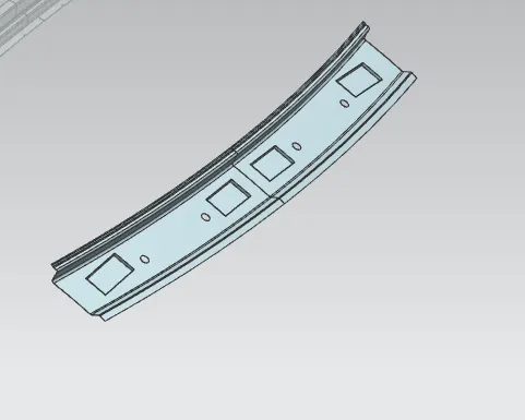
Bow roofs
Bow roofs are act as Reinforcement

Central roof rail
central roof rail helps in providing effectively support to the flat area of the roof as it is more susceptible to failure under the action of load . generally central roof rail is placed at the center of the roof which is connected to the B-pillar support structure . This central roof rail helps in adding the strength to the roof during the rool- over test. The thickness of the central roof rail is 1.25 mm .

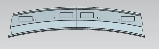
Rear roof rail
Rear roof rail is the one which joins the back door and the body side outer
Testing of Roof
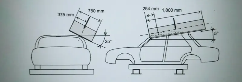
Roof crush test is the design given by the IIHS ( insurance institute of highway safety ) . After analyzing the many accidents IIHS has then fixed some regulations , that how to perform the crush test . IIHS gives the rating based up on this test . For this they consider two points while giving the rating ,How fast the car can reforms to its original shape after the roll over andHow deep is the protrusion after the roll over.
Goal of roof crush teat
To minimize the protrusion into the occupant compartment , so that the seat belts and air bags can do there job in protecting the occupant
Condition to follow for roof crush test
There are two conditions that should be followed for the roof crush test , they are
METHOD OF APPLYING THE FORCE :
The load is applied in such a way that 50 is tilted from the front end to the rear end and the load will be in 1800 mm in length and 750 mm in width . The load is applied at the position of 250 from the flatness of the roof . The load is applied on the roof for almost 120 sec and the crush speed at which the load applied is 13 mm/sec or less than that
HEAT DISTORTION STUDY ON THE ROOF :
W = [1.73 x 10^(-3) x L] + [1.85 x 10^(-8) x (R^2)/t] + [ 1.10x10^(-3) x l] - 2.68
Where,
L = Roof Length in X-Direction[mm](Roof dimension in 0-Y)
R = Roof curvature
R = 2(Rx*Ry)/(Rx+Ry)
Rx = X curvature
Ry = Y curvature
t = Roof plate thickness [mm]
l = Bow Roof Span [mm]
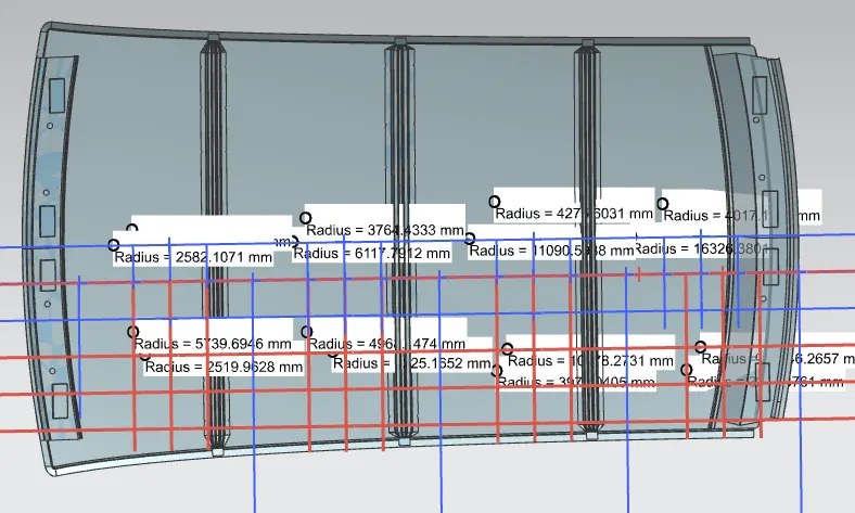
| Heat Distrotion calculation | ||||||||||
| Rx | Ry | Rx*Ry | Rx+Ry | R | L(Roof length) | l | W | Status | Result | |
| Front roof rail to Bow 1 | 5739.695 | 2519.963 | 14463817 | 8259.657 | 3502.28 | 2028 | 356.99 | 1.334589185 | W<2.7 | Pass |
| Bow1 to Bow 2 | 4968.147 | 6225.165 | 30927538 | 11193.31 | 5526.074 | 2028 | 432.77 | 1.586958844 | W<2.7 | Pass |
| Bow2 to Center Bow | 10578.27 | 3978.041 | 42080799 | 14556.31 | 5781.793 | 2028 | 433.07 | 1.614036496 | W<2.7 | Pass |
| Center Bow to Rear rail | 15046.27 | 3211.376 | 48319218 | 18257.64 | 5293.04 | 2028 | 282.7 | 1.398560562 | W<2.7 | Pass |
From the above table it can be concluded that all values of w<2.7 and also not w>3.1 so thus infers that current positioning of bow row are good in state as per design and found ok.
SNOW LOAD CRITERIA :
This test is done to know how is the roof behaving when there is a snow over . normally due to the snow weight the dent will happen. But the roof should be designed in such a way that when the snow is removal the roof should go it its original position . This is the basic requirements for snow load criteria .
Qr = [Iy x t2] / [α x s x [(Rx + Ry)/2]2 x 10-8]
Note: The Qr value given over here is correct. There was a typo error in the formula given in the video.
Where,
α = My x Lx2 x 10-12 , My = Y(Ly-Y)
t = Roof plate thickness [mm]
Ly = Distance between the front and rear roof Rails on the Vehicle along with 0Y[mm]
Length of Roof panel with the center point between Roof rail Front /Rear as the front and rear reference point.
Lx = Distance between the Left and Right end of the roof on the Roof BOW [mm]
The width of the roof panel is exposed on the surface.
Y = Distance front Front Roof Rail to Roof BOW[mm]
s = Distance for which Roof BOW bears divided load [mm]
s = L1/2 + L2/2
Iy = Geometrical moment of inertia of Roof BOW (Y cross-section )[mm4]
Rx = Lateral direction curvature radius of roof panel Y cross-section on Roof BOW [mm]
Roof panel curvature Radius of the Length Lx in Front view
Ry = Longitudinal Direction curvature radius of the Roof panel X cross-section on Roof BOW [mm]
Roof panel X curvature radius of length s in Side view
| Snow Load Calculation | |||||||||||||
| Ly | Y | My | α | Lx | L1 | L2 | S | Iy | Rx | Ry | t | Qr | |
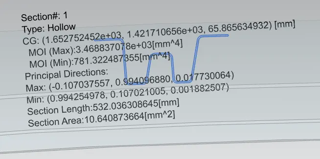
| Front roof rail to Bow 1 | 2028 | 477.7 | 740578.3 | 0.80101 | 1040 | 477.7 | 507.6 | 492.65 | 3468.8 | 4542.24 | 2582.107 | 0.75 | 38.96686 |
| Bow1 to Bow 2 | 2028 | 983.2025 | 1027248 | 1.111071 | 1040 | 507.6 | 507.6 | 507.6 | 4963.8 | 3764.433 | 6117.791 | 0.75 | 20.27795 |
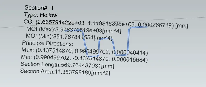
| Bow2 to Center Bow | 2028 | 1488.105 | 803420.8 | 0.86898 | 1040 | 507.6 | 471.5 | 489.55 | 3978.3 | 4275.603 | 11090.6 | 0.75 | 8.911282 |
| Center Bow to Rear rail | 2028 | 1957.7 | 1040 | 4017.181 | 16321.38 | 0.75 | |||||||
Section analysis:
Bow roof-1
Center Roof
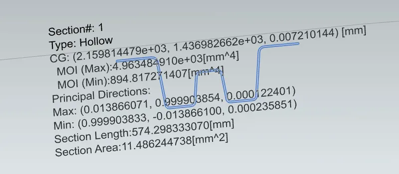
Bow roof 2
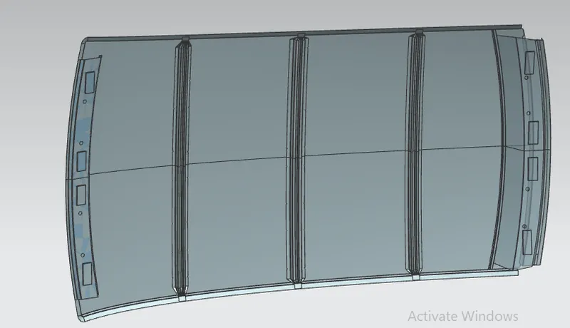
Draft Analysis
