Roof Design
ROOF:
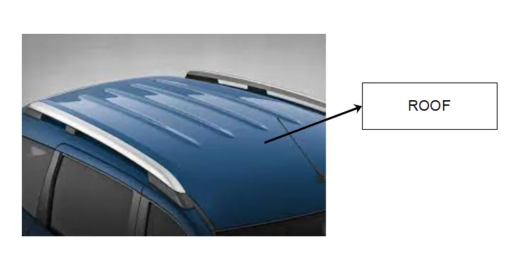
- An automobile roof or car top is the portion of an automobile that sits above the passenger compartment, protecting the vehicle occupants from sun, wind, rain, and other external elements.
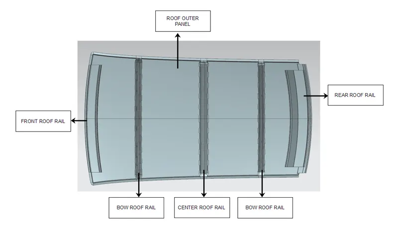
- The roof structure consists of
A) Roof Outer Panel
B)Front Roof Rail
C) Bow Roof Rail
D) Center Roof Rail
E) Rear Roof Rail.
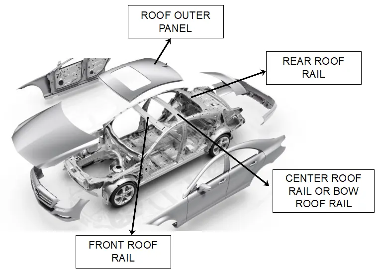
- The roof structure varies based on features like sunroof, convertible roof etc. and structure of vehicle.
- The reinforcement structure such as center roof rail and bow roof rail provided varies based on the designed roof.
OBJECTIVE:
- To design a roof assembly from given roof styling by developing the essential flanges for outer roof and reinforcements.
- To provide appropriate dimensions and perform draft analysis.
- To do a curvature study on the roof and perform calculations to determine the position of the Bow-roofs.
ROOF DESIGN CONSIDERATION:
- The factor that are considered while design of roof are :
a) Visibility
b) Head Clearance
c) Heat distortion and Snow load criteria
d) Draft Analysis
e) Curvature
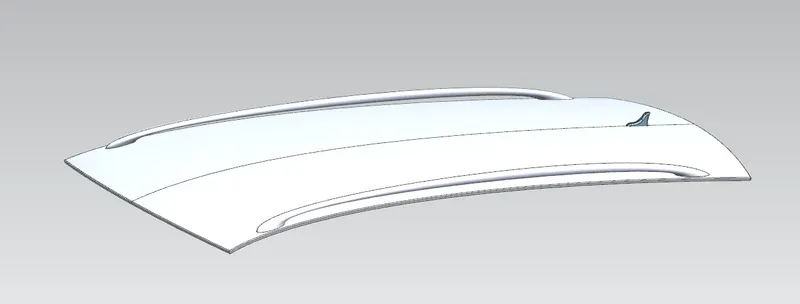
GIVEN ROOF STYLING :
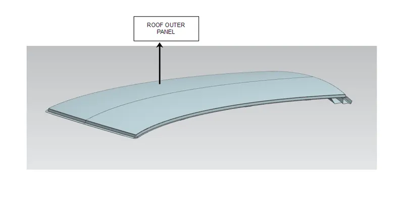
DESIGNED ROOF ASSEMBLY:
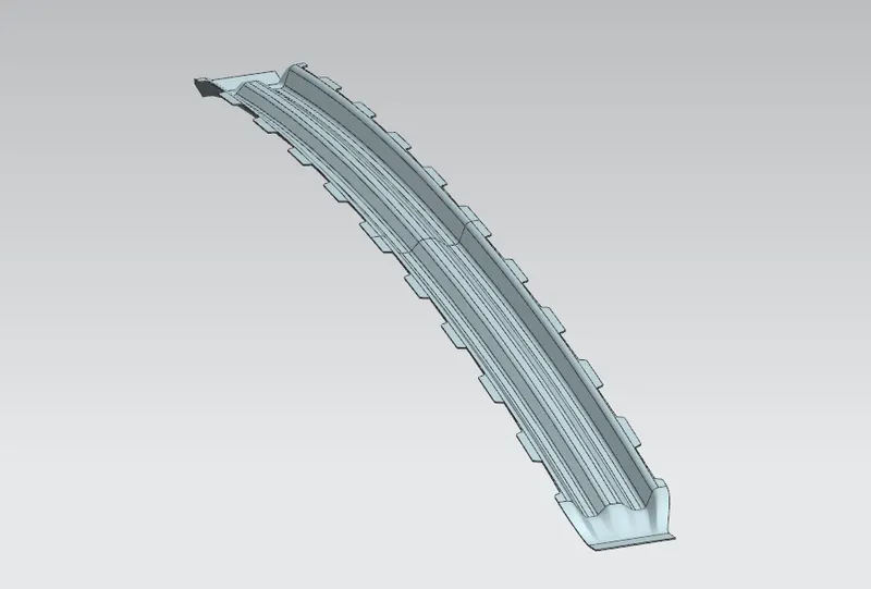
- The roof assembly is designed based on the design factors such as visibilty, heat distortion and snow load criteria, curvature etc.
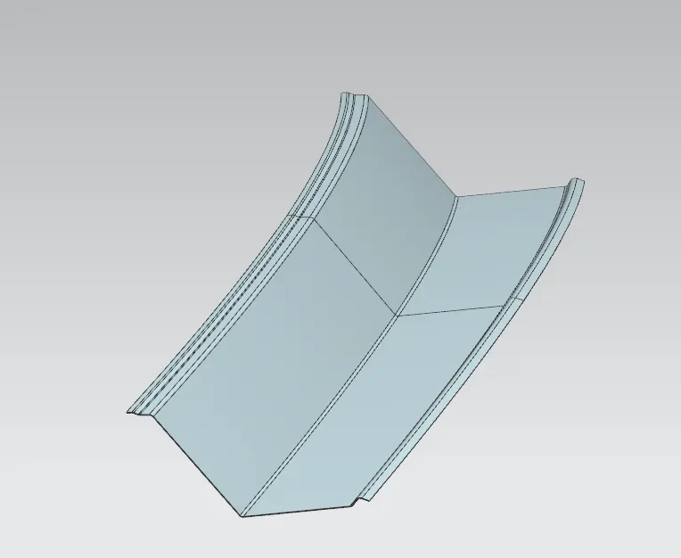
- The reinforcement members such as front roof rail, rear roof rail, bow roof etc. are designed according to the master section provided. The provision for mastic seals and spot weld is provided for the following reinforcement members.
Isometric View:
Roof Assembly:
Front Roof Rail:
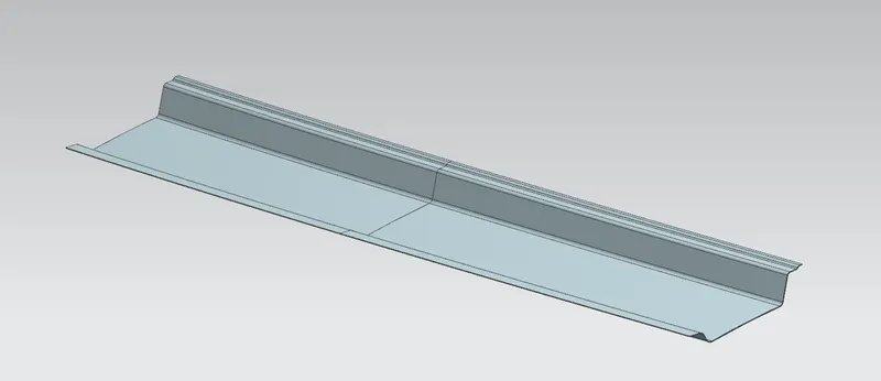
Bow Roof 1:
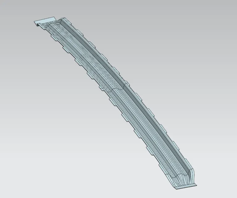
Center Roof Rail:
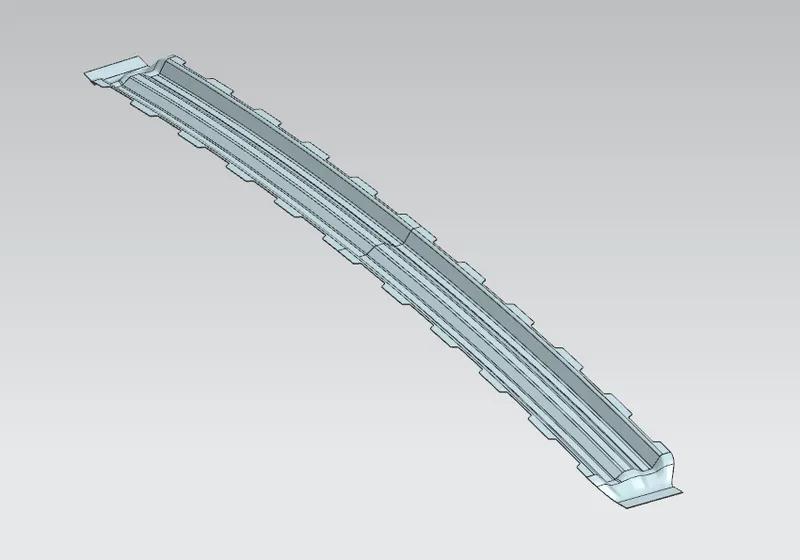
Bow Roof 2:
Rear Roof Rail:
DRAFT ANALYSIS :
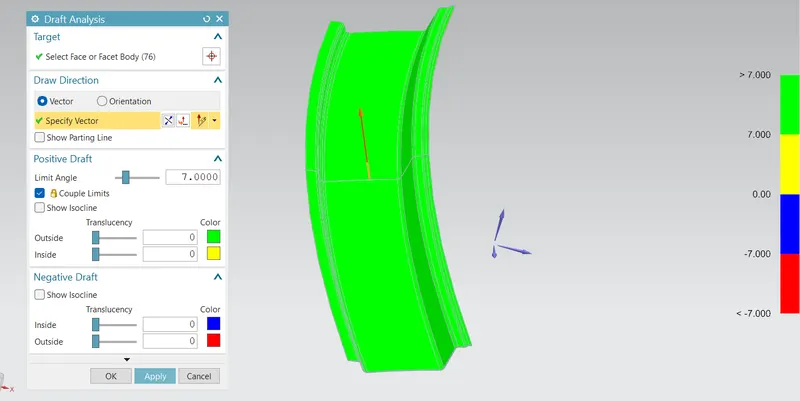
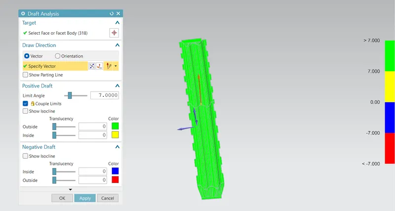
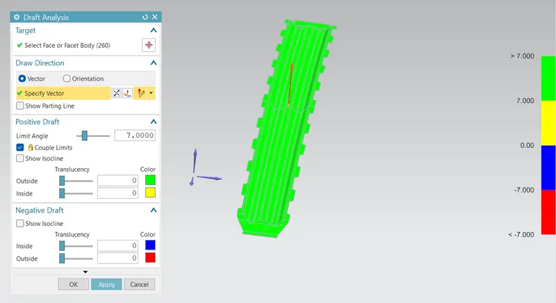
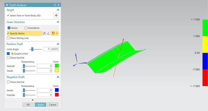
- The draft analysis is performed to check whether the designed part is manufacturable or not. The other criteria for which draft analysis performed to increase the tool life and maximum number quality of quality parts during manufacturing.
- The following reinforcements like Front roof rail, rear roof rail, bow roofs and center roof rail are sheetmetal components. The condition for good sheetmetal design for manufacturability is that minimum draft should not be less than 7 degree.
Front Roof Rail:
Bow Roof 1:
Center Roof Rail:
Bow Roof 2:
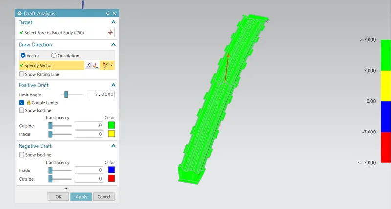
Rear Roof Rail:
Section Analysis:
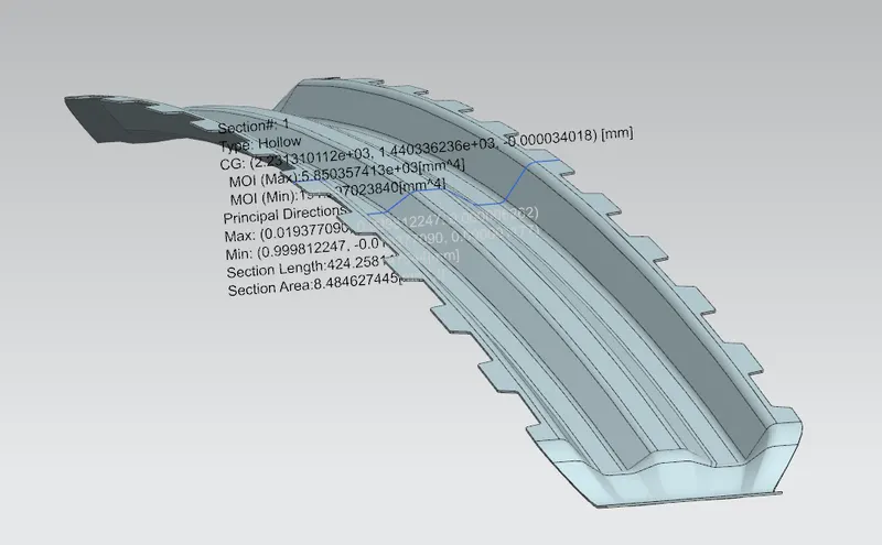
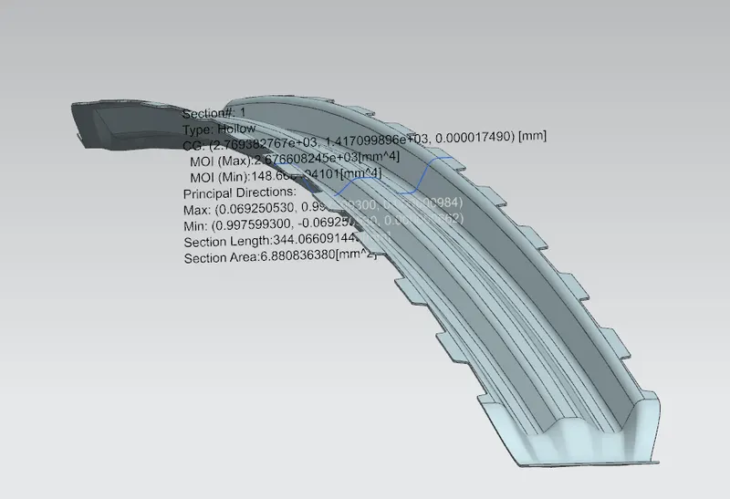
- The section analysis is done on designed bow roofs and center roof rail to find the moment of inertia (minimun).
- The moment of inertia (Iy) is used to calculated results for snow load condition.
Bow Roof 1:
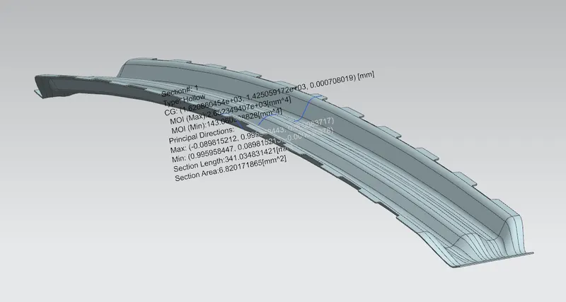
Center Roof Rail:
Bow Roof 2:
HEAT DISTORTION PERDICTION:
Formula:
W = [1.73 x 10^(-3) x L] + [1.85 x 10^(-8) x (R^2)/t] + [ 1.10x10^(-3) x l] - 2.68
Where,
L = Roof Length in X-Direction[mm](Roof dimension in 0-Y)
R = Roof curvature
R = 2(Rx*Ry)/(Rx+Ry)
Rx = X curvature
Ry = Y curvature
t = Roof plate thickness [mm]
l = Bow Roof Span [mm]
Judgment Condition:
OK<2.7
Heat Distortion Sketch for calculating values:
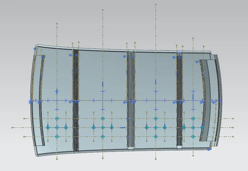
Table:
|
S.No |
BOW |
Rx |
Ry |
R |
l |
L |
t |
R2 /t |
W |
OK/NG |
|
1 |
FR TO BW1 |
5742.09 |
2419.58 |
3404.55964 |
346.43 |
2028.3 |
0.75 |
15454701.75349 |
1.496 |
OK |
|
2 |
BW1 TO CR |
7814.89 |
6354.3 |
7009.31465 |
532.3 |
2028.3 |
0.75 |
65507322.49464 |
2.626 |
OK |
|
3 |
CR TO BW2 |
3828.16 |
11362.14 |
5726.82434 |
459.52 |
2028.3 |
0.75 |
43728689.31427 |
2.143 |
OK |
|
4 |
BW2 TO RR |
2601.36 |
7054.65 |
3801.09058 |
232.23 |
2028.3 |
0.75 |
19264386.12627 |
1.441 |
OK |
- The designed roof satisfies the judgement condition i.e. (W<2.7).
SNOW LOAD CRITERIA :
Formula:
Qr = [Iy x t2] / [α x s x [(Rx + Ry)/2]2 x 10-8]
Note: The Qr value given over here is correct. There was a typo error in the formula given in the video.
Where,
α = My x Lx2 x 10-12 , My = Y(Ly-Y)
t = Roof plate thickness [mm]
Ly = Distance between the front and rear roof Rails on the Vehicle along with 0Y[mm]
Length of Roof panel with the center point between Roof rail Front /Rear as the front and rear reference point.
Lx = Distance between the Left and Right end of the roof on the Roof BOW [mm]
The width of the roof panel is exposed on the surface.
Y = Distance front Front Roof Rail to Roof BOW[mm]
s = Distance for which Roof BOW bears divided load [mm]
s = L1/2 + L2/2
Iy = Geometrical moment of inertia of Roof BOW (Y cross-section )[mm4]
Rx = Lateral direction curvature radius of roof panel Y cross-section on Roof BOW [mm]
Roof panel curvature Radius of the Length Lx in Front view
Ry = Longitudinal Direction curvature radius of the Roof panel X cross-section on Roof BOW [mm]
Roof panel X curvature radius of length s in Side view
Judgment Condition:
Qr ≥ 3.1
250 ≤ s ≤ 380
Snow load Sketch for calculating values:
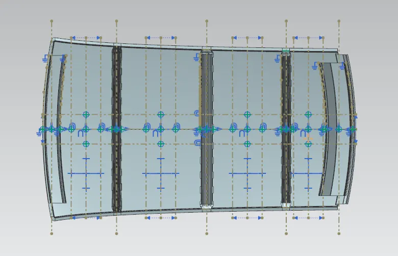
Table:
|
S.No |
BOWS |
lY |
My |
ά |
Lx |
Ly |
y |
s |
Rx |
Ry |
t |
Qr |
Determination |
|
1 |
FR TO BW1 |
143.06 |
661377.4524 |
0.84093 |
1127.6 |
1944.85 |
439.29 |
525.04 |
4612.59 |
2103.35 |
0.75 |
1.61635 |
NOT OK |
|
2 |
BW1 TO CR |
191.29 |
939578.5284 |
1.10157 |
1082.78 |
1944.85 |
1050.09 |
574.49 |
3773.76 |
6268.71 |
0.75 |
0.67437 |
NOT OK |
|
3 |
CR TO BW2 |
148.66 |
566320.6824 |
0.63908 |
1062.3 |
1944.85 |
1588.29 |
447.37 |
4331.92 |
12059.63 |
0.75 |
0.43542 |
NOT OK |
|
4 |
BW2 TO RR |
0 |
0 |
1944.85 |
1944.85 |
3914.02 |
16910.8 |
0.75 |
#DIV/0! |
- The designed roof do not satisfies the judgement condition i.e. (Qr ≥ 3.1), 250 ≤ s ≤ 380.
ROOF MANUFACTURING TECHNIQUES:
Stamping Process :
- There are basically only three components to sheet metal stamping are the sheet metal, die, and press machine, but any single part can require multiple steps to arrive at its final form. The following common processes that might occur during metal stamping.
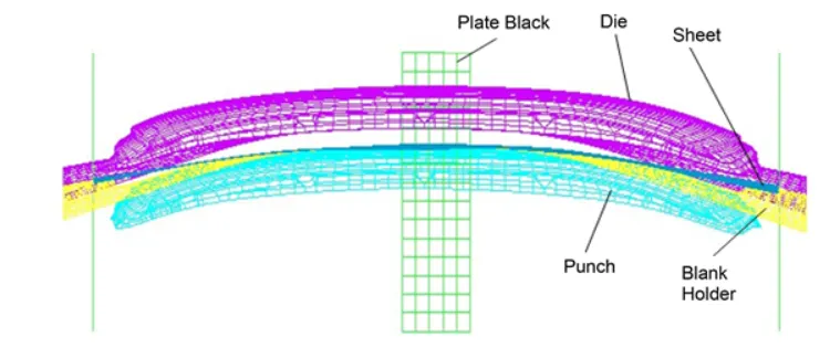
- Forming: Forming describes the process of transforming the flat metal into another shape by applying force. It is accomplished in one of several ways, depending on the design specifications for the part. With a series of operations, the metal can be altered from a relatively simple shape into a complex one.
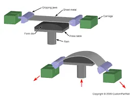
- Blanking: Blanking is the most basic technique and initiates when the sheet or blank is fed into the press where the die cuts out the desired shape. The resulting piece is called a blank. The blank may be the desired part, also known as a fully finished blank, or it may continue to the subsequent step of forming.
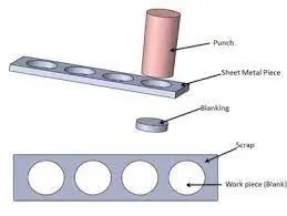
- Drawing: Drawing is a more complicated operation and is how vessels or deep depressions are formed. Tension is used to carefully draw the material into a cavity to change its shape. Though the material might stretch while it’s drawn, technicians try to avoid stretching as much as possible to keep the material intact. Sinks, cooking equipment, and oil pans for vehicles are usually made with drawing.
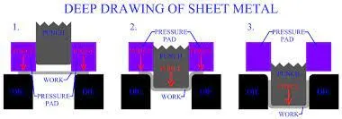
- Piercing: Piercing is almost the opposite of blanking, but instead of saving the blanks, technicians use the material around the outside of the punched area. As an example, think of cutting biscuits from a rolled-out circle of dough. During blanking, the biscuits are saved; during piercing, on the other hand, the biscuits are discarded, and the hole-riddled remains are the desired outcome.
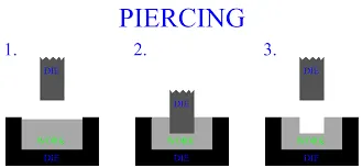
- The outer panel and reinforcement structure are formed using these sheetmetal operations. Further there are joined together by other manufacturing techniques such as spot welding and mastic sealent.
Spot Welding:
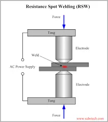
- Spot welding (or resistance spot welding) is a type of electric resistance welding used to weld various sheet metal products, through a process in which contacting metal surface points are joined by the heat obtained from resistance to electric current.
The process uses two shaped copper alloy electrodes to concentrate welding current into a small "spot" and to simultaneously clamp the sheets together. Work-pieces are held together under pressure exerted by electrodes. Typically the sheets are in the 0.5 to 3 mm (0.020 to 0.118 in) thickness range. Forcing a large current through the spot will melt the metal and form the weld.
Mastic Sealent:
- A sealent is used to join the two part where the spot welding cannot be used and to protect the asthetic appearence of the outer panel.
- The sealent also provides strength to the joined parts and prevents the unnecessary movements between the parts.
Roof Strength Test :
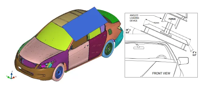
In the test, the strength of the roof is determined by pushing an angled metal plate down on one side of the roof at a slow but constant speed and measuring the force required to crush the roof. The force applied relative to the vehicle's weight is known as the strength to weight ratio. The peak Strength to Weight ratio (SWR) recorded at any time before the roof is crushed five
inches is the key measurement of roof strength.
Conclusion:
- The roof assembly was successfully modeled according to the provided master section.
- The draft analysis was performed and the designed parts had more than 7 degrees of draft.
- The designed roof assembly was successful in heat distortion prediction criteria but failed in snow load prediction criteria. Therefore the designed roof assembly is not suitable in snowing areas and requires design changes for improvement.
- The improvements that can be done to improve roofs snow load conditions are
- Providing additional bow roofs for support.
- By changing the positions of existing bow roofs to center roof rail.
- By increasing the thickness of the reinforcements.