Roof Design
Aim:
For the given roof styling, develop the essesntial flanges and reinforcements, provide appropriate dimensions and check for draft analysis and to perform roof curvature study using NX-CAD
Introduction:
Roof
An automobile roof or car top is the portion of an automobile that sits above the passenger compartment, protecting the vehicle occupants from sun, wind, rain, and other external elements.
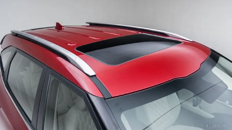
The roof is a styling surface part which is fixed with the BIW body through the rails and panels inside the upper roof to provide it strength and stiffness.
Ditch area plays an important role here to fix the reinforcement on the component.
The rails and reinforcements are joined to the ditch area with a spot weld where it's not the styling part.
The required tool opening angle is minimum 3 Degrees.
Factors which is considered before creating Ditch area,
- Headroom clearance
- Visibility criteria
- Back door assembly
- Windshield assembly
Software Using NX CAD:
Class A Styling Input
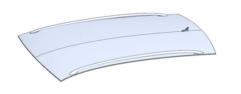
- After the file is opened, the roof part is not joined together but as the individual surfaces.
- It is also seen as the surface is perfectly symmetrical in shape which helps us to work on the half of the portion and reflect it which creates the whole roof. We work on the half of the surface and mirror to complete the rest.
Components of roof:
- Front roof rail
- Rear roof rail
- Bow roof
- Centre roof rail
- Ditch area
Front roof rail:
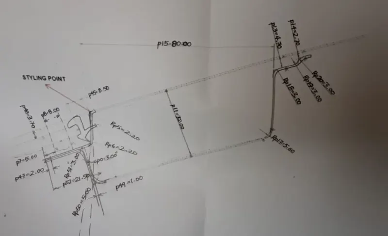
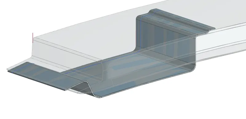
It is created using Given reference master section
Designed:
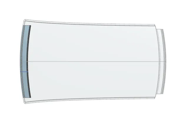
Front roof rail is used to provide strength to the roof panel front and it also acts as link between windshield glass, roof panel and headliner. Spot welds are applied at wind shield end of the rail and the other end is joined with roof using mastic sealent which also increases the strength.
Rear roof rail:
It is created using Given reference master section
Designed:
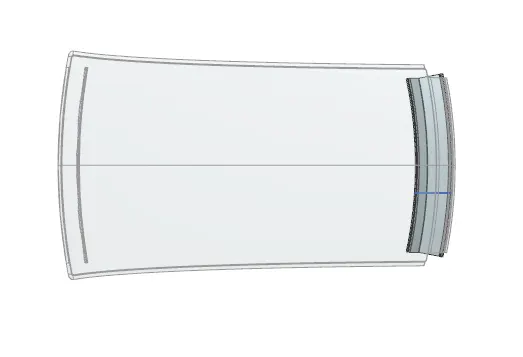
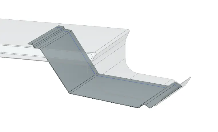
Rear roof rail is again used to strengthen the roof and it acts as a link between back glass and roof which connected to the backdoor of the car.Spot welds are applied at back doorend of the rail and the other end is joined with roof using mastic sealent.
Center Roof rail and Bow roof rails:
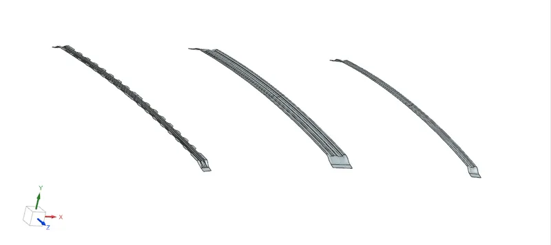
Center roof rail will be at the centre of the roof to provide strength and stability to the roof. Here the centre roof rail is joint with the roof through mastic sealent.
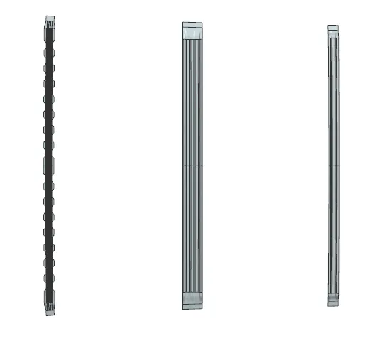
Bow roof is used for strengthening purpose and also attached to the upper roof surface with mastic sealants
Ditch area:
Ditch area is a extended portion of the maim roof concellled by other BIW pannels.The rails support of the roof are attached to the ditch area using spot weld.

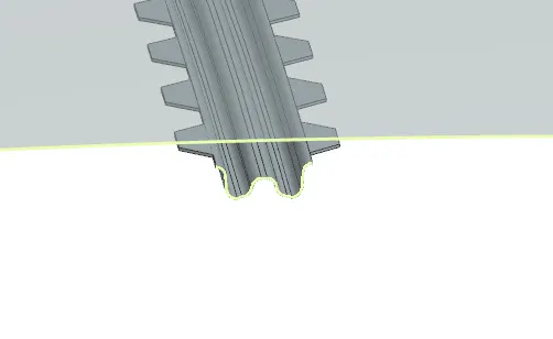
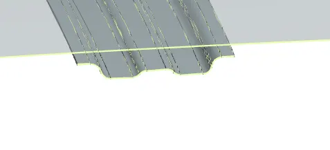
Sectional view:
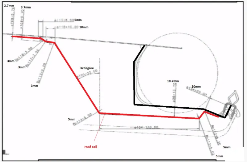
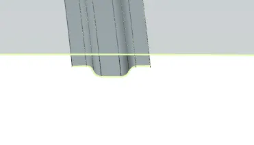
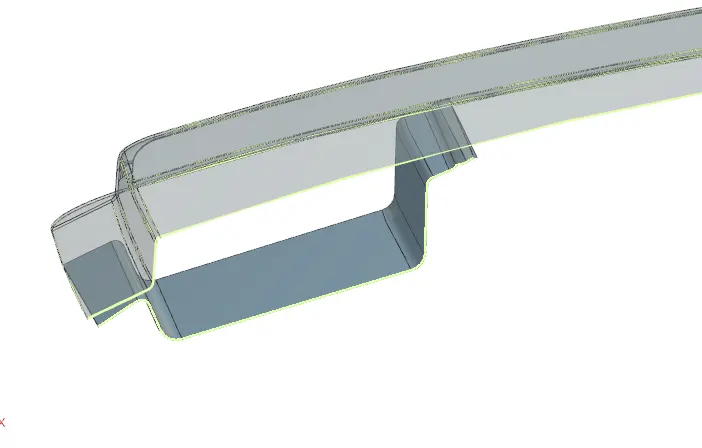
Note: 5mm distance is given between outer panel and the roof rail for mastic sealants
Final Model:
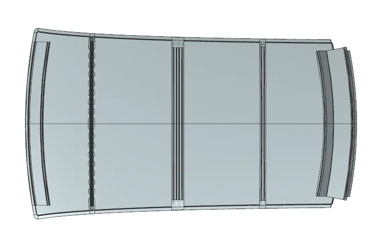
Note: All the components above has created with thickness of 0.75mm
Curvature study on the Roof:
After getting the final body it has to be checked and justify that it passes the standards.
Analysis:
It is done to justify the position of the bow roofs.
1.Roof crash test.
2.Snow load test.
3.Heat distortion criteria
Heat distortion criteria:
Heat distortion temperature is a temperature at which the metal softens and deform under a specific load.This study is done to check the ability of the roof to withstand high temperature with respect to the position of the reinforcement which contribute to the increase strength.
- To calculate the heat distortion criteria by the bow roof position formula,
- We need to create a sketch , draw a line on the center of the roof on OY axis (mid horizontal axis)
- Next draw a line from the center line by a 300mm distance
- After that draw a line from 100mm distance on both sides of the 300mm line
- Then draw a line between the center of roof rails and draw the lines from the center line by the distance of 100mm on both sides.
- Atlast make an intersection on these lines from a coincident line to get points.
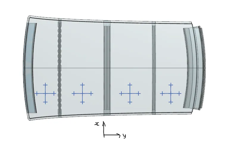
- Roof curvature (Rx & Ry) radius is measured by creating a 'Three point arc'
Prediction formula:W=[1.73×10⁻³×L] + [1.85× 10⁻⁸×R2/t]+[1.10×10-3×l]-2.68
Judgemental condition:Ok<2.7>3.1
Where
L=Roof length in X-direction in mm (Roof dimension in O-Y)
R=Roof curvature
R=2(RX×RY)/(RX+Ry)
RX=X Curvature
Ry=Y Curvature
T =Roof plate thickness in mm
L =Bow roof span in mm

The test value infer that the design is good and under the limit of standards.
Snow Load criteria:
Snow load criteria study is done to check the ability of the to withstand snowfall and bounce back to its orginal shape without any permenant deformation once the load is removed.
- To calculate the snow load condition, we have a snow load formula
- To measure the required values
- Created a sketch and draw a line on OY axis from the center of the roof
- From that line draw a parallel line distance of 100mm on both sides
- Then make intersection points of these lines and draw a three point arc
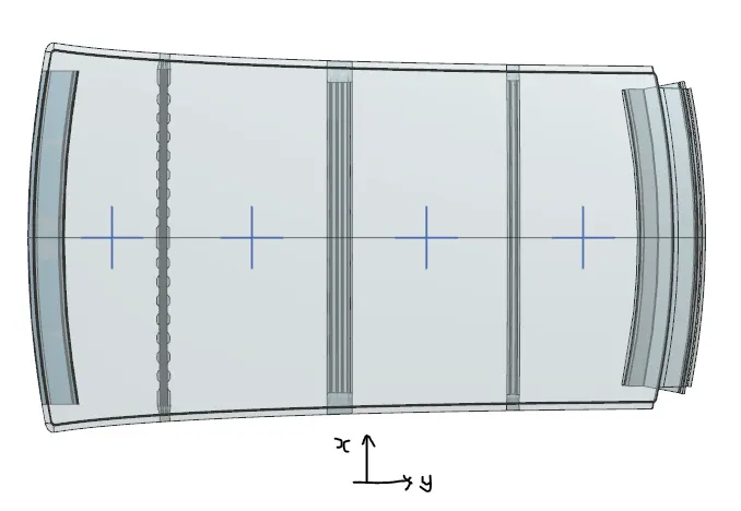
- Roof curvature (Rx & Ry) radius is measured by creating a 'Three point arc'
Snow load prediction formula :Qr =[(Iy × t2)/(α × s×(RX+RY/2)2 × 10-8)]
Where
α = My× Lx2× 10-12 ,My=Y(Ly -Y)
Judgement Condition:Qr≥3.1
t=Roof plate thicness in mm
LY =Distance between Front and rear roof rail on vehicle O-Y in mm i.e length of the roof panel with the centre point between roof rail FR/RR as the referance point of the front and rear
Y=Distance from front roof rail centre to bow roof in mm
S - Distance for which BOW bears divided load in mm
S= L1/2+L2/2
Iy=Geometrical moment of inertia of roof BOW (Cross-section)mm4
Rx=Lateral direction curvature radius of roof panel Y cross section on Roof ROW in mm
Ry =Longitudinal direction of the curvature radius of roof panel X cross section on BOW roof (mm)

The test value infer that the design is good and under the limit of standards.
Section Modulus
Section modulus is a direct measure of strength of any sectional area of an object about an referance axis(neutral axis). Strength is nothing but,capable of supporting greater loads,so higher the strength it has a high capable of supporting greater loads.
Section modulus represented with a symbol of ‘S’
S=I/Y
S-Section modulus
I-Distance from the referance line to one of the extreme end of the object
Bow roof 1:
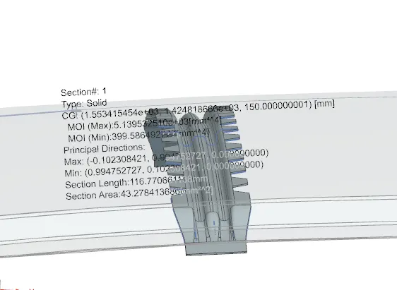
I=399.421mm4
Y=15mm
S=26.6mm3
Center roof rail:
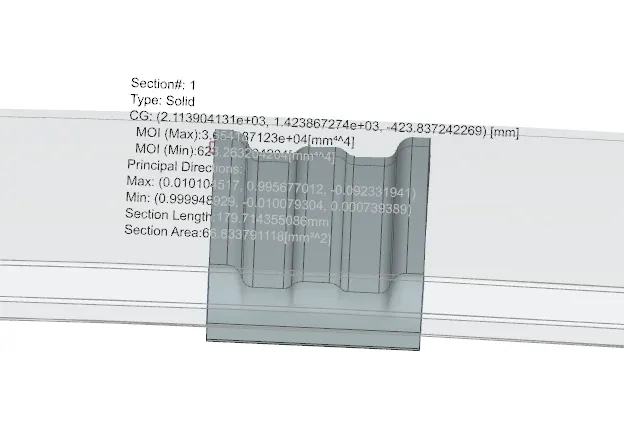
I=623.261mm4
Y=35mm
S=17.80mm3
Bow roof 2:
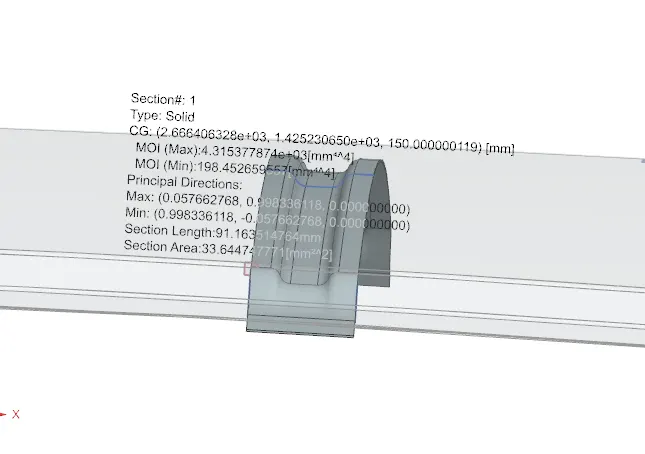
I=198.451mm4
Y=15mm
S=13.2mm3
Draft Analysis
It is done to check if the features designed clear the minimum draft 5 degree for manufacturabililty. This type of analysis is performed based on color ranges identifying zones on the analyzed element where the deviation from the draft direction at any point, corresponds to specified values.
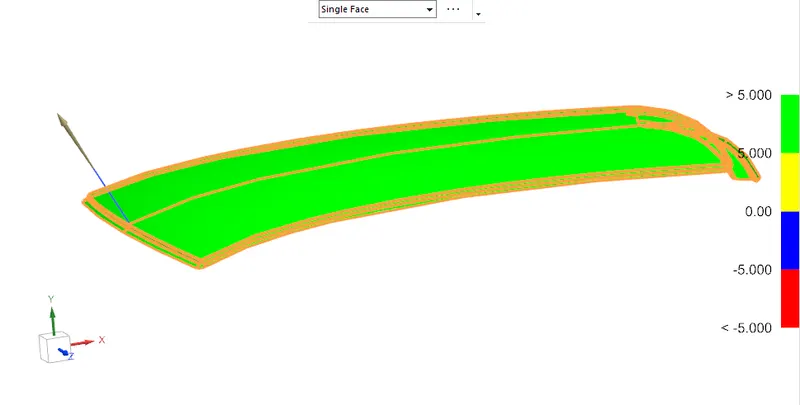
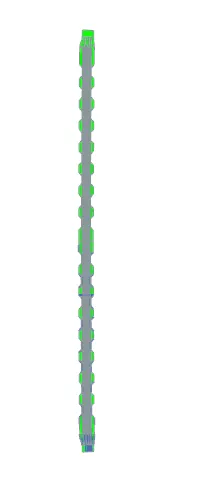
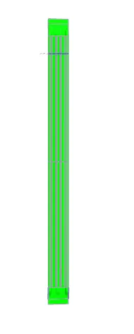
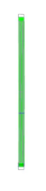
It is seen that the features designed clears the minimum draft angle which denoted in 'green'
Conclusion:
- Essential roof components such as bow and center rails required with flanges and reinforcements are designed.
- Curvature study on roof was analysied with heat distortion and snow load standards
- Draft analysis was done to check toolablilty.