Roof Design
OBJECTIVE:
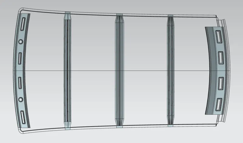
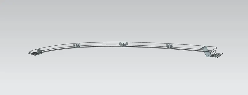
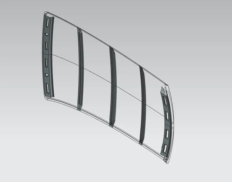
1.Main objective of the project is to create the Roof Sheetmetal design in NX cad, and also designing Front roof rail, rear roof rail, bow roof front, bow roof rear, center roof rail and Reinforcement are creating to build the strong roof.
2.Do curvature study on Roof and performance calculations for Heat distortion and Snow load criteria to determine the position of the Bow roofs.
3.Finding the moment of inertia and section modulus for Bow-roofs and center roof rail.
4 Also finding the Draft Analysis of each part.
SOFTWARE USED: NX 12.0
- To design the Sheetmetal ROOF in NX by using some Solid/Surface features.
- NX Software is a flexible and powerful integrated solution that helps you deliver the products faster and efficiently.
- NX Cad software is widely used automotive, aerospace, thermal power station. Because of it is having modelling, drafting and manufacturing platform.
INTRODUCTION:
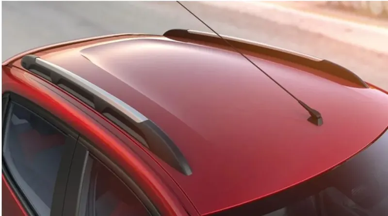
An automobile roof or car top is the portion of an automobile that sits above the passenger compartment, protecting the vehicle occupants from sun, wind, rain, and other external elements.
When it is seeing from outside of the car, it is just closing the top portion. But in design point of view, it is hard to create the design. Because of you have to create no of support rails for enough strength to withstand the load. Bow roofs are primarily fixed in flatter region to enhance strength.
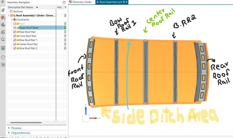
Front roof and rear roof rails are fixed to the ditch area using spot weld operation. But front, rear bow roof and center roof rails are fixed to roof using mastic sealants. We don’t want so much gap between roof rails and bow roof area. So, we reducing the NVH issues.
DESIGN CONSIDERATION OF ROOF:
- Visibility criteria
- Head room clearance
- Bow roof position
- Heat distortion and Snow load criteria
- Draft analysis
ROOF CRUSH TEST:
OVERVIEW OF THE TEST:
Roof strength evaluations consist of a quasi-static test conducted on a vehicle’s roof in a manner similar to tests used to judge compliance with Federal Motor Vehicle Safety Standard 216 (Office of the Federal Register, 2009). The main differences between the procedure specified by the Insurance Institute for Highway Safety (IIHS) and that specified by the U.S. federal government are that the IIHS procedure are,
- Specifies testing one side of a vehicle’s roof
- Does not include a headroom criterion
- Specifies testing to a given displacement instead of a given force level
- Specifies setting the vehicle’s pitch angle during testing based on the measured on-road pitch angle.
An overall rating is assigned based on the peak strength-to-weight ratio (SWR) measured within 127 mm of plate displacement.
CURB WEIGHT MEASUREMENT:
Curb weight values used for calculating the SWR are based on IIHS measurements of a vehicle, not the manufacturer’s specified curb weight.
Vehicle curb weight is measured with full fluid levels using scales manufactured by Longacre Racing Products (Computer scales DX series 72634).
TEST VEHICLE SELECTION:
For information on how we select vehicles for our crash test programs, including how we define typically equipped vehicles, see Test Vehicle Selection (IIHS, 2021). Whenever possible, the vehicle acquired for testing is the same vehicle used for the curb weight measurement.
At times, it is necessary to test a vehicle that does not meet the IIHS definition of a typically equipped vehicle, and the curb weight measurement is applied from another vehicle that does meet the definition. In these cases, the test vehicle does not differ from our typically equipped vehicle definition in any way that might influence the roof strength (e.g., a vehicle with a sunroof would not be tested if the typically equipped vehicle lacks this option).
Once the test vehicle has been acquired, either the driver or passenger side of the vehicle is selected for testing. For most vehicles, the test side is chosen at random. However, for roof designs that appear asymmetrical, engineering judgment is used to select the side of the roof that may result in a lower peak force.
TEST VEHICLE PREPARATION:
With the vehicle on a level surface, the on-road pitch angle at the front door sill is measured on both sides of the vehicle. Unless the vehicle manufacturer requests otherwise, roof racks and other nonstructural items that may be contacted during the test are left as installed from the factory.
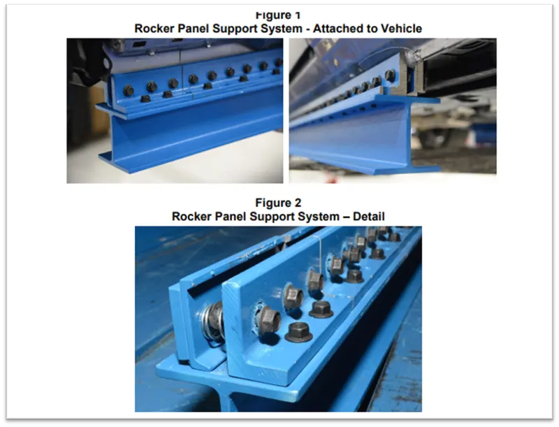
Any trim or other components are removed if they interfere with supporting the vehicle along its rocker panels. For vehicles with vertical pinch weld flanges on the bottom of the rocker panels, the vehicle support system consists of one I-beam (HR A-36 W4X13) for each rocker panel.
Each I-beam has a clamping system incorporated on the top that is tightened against the pinch weld flange to clamp the system in place (Figures 1 and 2). When the pinch weld flange has a bend that prevents supporting the sill with one I-beam, more than one I-beam can be used on each side of the vehicle.
For vehicles with no pinch weld flange, or with a nonvertical flange angle that precludes clamping, mounting by another method may be necessary, such as that described in the National Highway Traffic Safety Administration’s Laboratory Test Procedure (2006).
Prior to testing, the front-row seat back on the side being tested is reclined to prevent interaction with the crushing roof. Rear seats are latched in their upright position. All windows are closed and doors are locked.
TESTING OF ROOF:
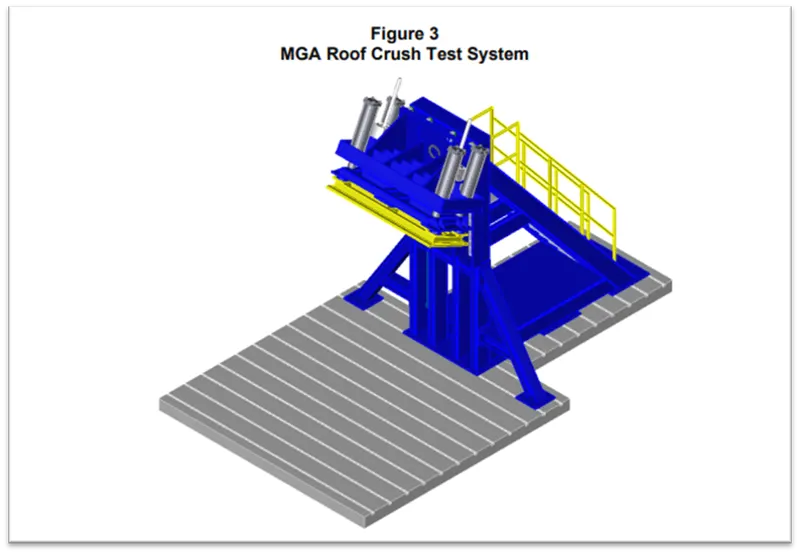
Roof strength evaluations are conducted on a quasi-static test system manufactured by MGA Research Corporation (Figure 3).
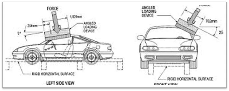
The system consists of an upright assembly and an attached loading head that can be fixed at varying heights from the ground as well as at pitch angles ranging from −5 to +5 degrees to accommodate testing on the driver or passenger side.
The roll angle is permanently fixed at 25 degrees. Four hydraulic actuators control the movement of the platen along two linear guides. The entire system is mounted on a T-slot bed plate anchored to the floor of the test facility.
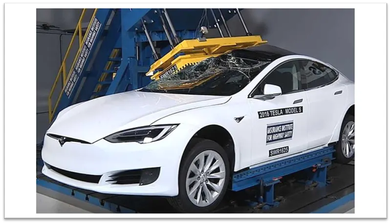
Two HR A-36 — W10x88 I-beams are mounted on the bed plate perpendicular to the longitudinal axis of the platen. The vehicle, with attached rocker panel support system, is placed on these beams. The vehicle is adjusted so that:
- The longitudinal centerline of platen is within 10 mm of the initial roof contact point.
- The yaw angle of the vehicle relative to the longitudinal axis of the platen is 0 ± 0.5 degrees.
- The midpoint of the platen’s forward edge is 254 ± 10 mm forward of the most forward point of the roof (including windshield trim if it overlaps the roof) lying on the vehicle’s longitudinal centerline.
- The pitch angle of the vehicle matches the on-road angle, while also accounting for any difference between the platen’s pitch angle and the nominal −5 degrees. The maximum combined difference of the vehicle and platen pitch angles from their targets is ± 0.5 degrees. (For example, if the onroad vehicle pitch angle is −0.2 degrees and the platen pitch angle is −5.2 degrees, the target sill angle for the test is −0.4 ± 0.5 degrees.) If necessary to achieve this angle, shims are inserted between the rocker panel supports and the W10x88 I-beams attached to the bed plate.
Once the vehicle is positioned correctly, the rocker panel supports are clamped to the two perpendicular I beams, and the beams are marked to allow confirmation that the vehicle position is maintained during the test.
For body-on-frame vehicles, the frame is supported to prevent the weight of the chassis from stressing the body at the body mounts. The roof is crushed to a minimum displacement of 127 mm at a nominal rate of 5 mm/second.
Some tests are conducted to a greater displacement to collect additional strength data for research purposes. Force data are recorded from five load cells (Interface Inc., model 1220) attached to the loading platen.
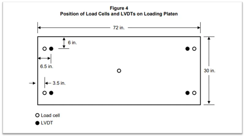
Displacement data are recorded from four linear variable displacement transducers (LVDTs) (MTS Temposonics model GH) integrated into the hydraulic actuators. Figure 4 shows the locations of the load cells and LVDTs on the loading platen.
Force and displacement data are collected with a National Instruments USB-6210 data acquisition system and reported at 100 Hz. These data are based on a sampling rate of 2,000 Hz, with every 20 points being averaged to produce the output data at 100 Hz.
The displacement-time histories from the LVDTs are compared to verify that the platen’s roll angle and pitch angle (relative to the vehicle’s on-road pitch) were maintained at 25 ± 0.5 degrees and −5 ± 0.5 degrees, respectively.
The precrash and post-crash conditions of each test vehicle are documented with still photographs. The position of the vehicle in the test fixture also is recorded. Motion picture photography is made of the test with real-time video cameras.
CALCULATING THE STRENGTH-TO-WEIGHT RATIO (SWR) RATING:
Force and displacement data are recorded for 5 seconds prior to each test, while the test system holds the loading platen at initial roof contact.
The data recorded from 1 to 4 seconds of this hold time are averaged for each channel to produce a measurement offset that is subtracted from the data recorded during the crushing of the roof.
After removing the offset for each channel, the force-displacement curve is plotted using the summed output from the five load cells and the average displacement from the four LVDTs. The maximum force prior to 127 mm of platen displacement is divided by the measured curb weight to obtain the SWR.
Both the force and curb weight are rounded to the nearest pound prior to performing the calculation, and the resulting SWR is rounded to the nearest one-hundredth of a unit.
Displacement is rounded to the nearest 0.1 mm. (The maximum displacement where the load can be used for the vehicle rating is 126.9 mm.) The vehicle’s rating is assigned based on the boundaries listed in.
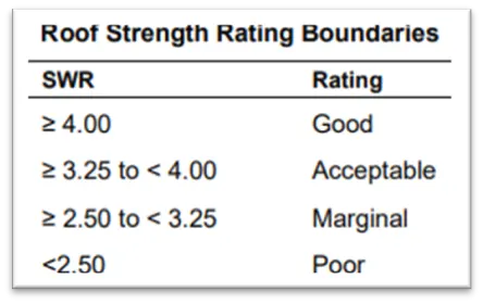
All trim levels sharing the tested vehicle’s body type and roof structure are assigned the same rating as the typically equipped trim level, provided their curb weights do not exceed 110% of the selected vehicle’s weight.
Based on published curb weights from multiple sources, any trim levels that may exceed this weight are identified and weighed. If the weight does exceed 110% of the weight of the selected vehicle, a unique SWR is calculated for that trim level.
If this SWR results in a lower rating, both ratings are reported for the model, with a split according to trim level. If a trim level weighs more than 110% of the typically equipped model, but the lower SWR does not fall in a lower rating band, only the original SWR and rating are reported for the model.
DESIGN SPECIFICATION FOR THE AUTOMOTIVE ROOF COMPONENT:
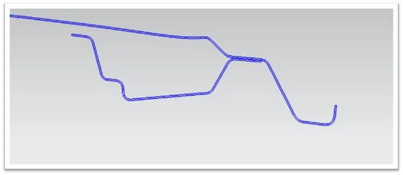
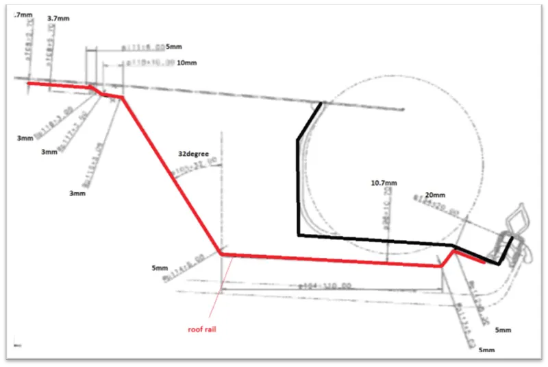
Master section data for front roof rail, rear roof rail, bow roof front, bow roof rear, Center roof rail and reinforcement. (*Master sections are only use in reference purpose only).
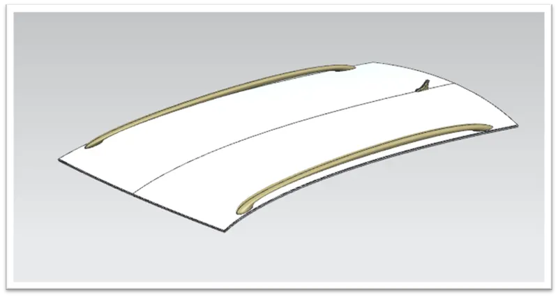
STYLING SURFACE FOR ROOF:
ROOF:
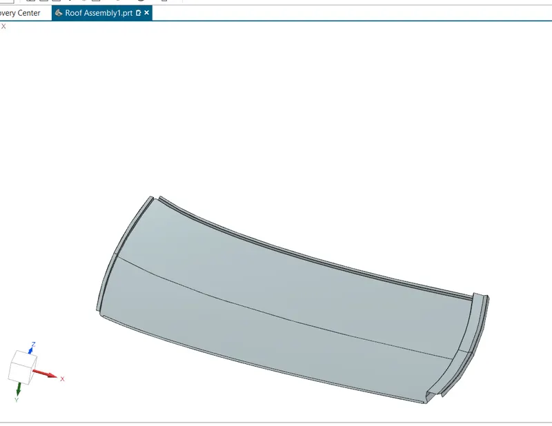
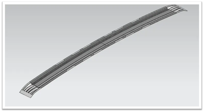
We can design the Roof, front roof rail, rear roof rail, bow roof, center reinforcement rails are creating with help of styling surface for roof.
FRONT DITCH AREA:
Front ditch area is creating with help of the dump solid of class A surface developed by considering the parameters to design the front ditch area,
We have to create the extension sheet with minimum 15mm, and give the positive draft angle 3 degree considering the following drawing operation.
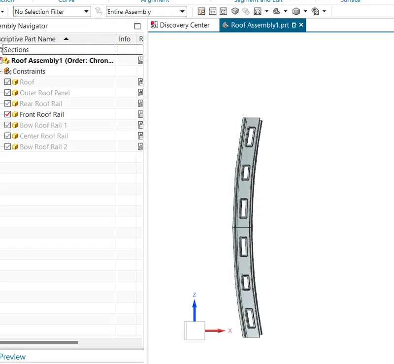
FRONT ROOF RAIL:
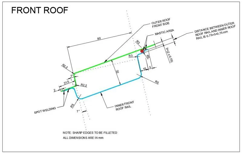
Front roof rail is used for supporting the roof for externally applied forces occurring at accidents. When we increasing the front roof rail is good for strength but also it is not for drivers because of it hide visibility of road.
When considering the parameters of roof rail, give them 60-80mm length, proper draft angle and also using the embosses for increasing the strength. Front section of front roof rails spot welded to the front ditch area and other end is fixed with help of mastic sealants.
Sheetmetal thickness t = 0.75mm
Embosses height = 2 < 3t
Flange length = 13.2 > 3t+R
Radius = (3mm or 5mm) > t
REAR DITCH AREA:
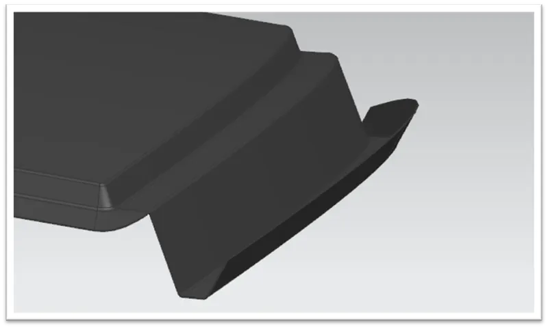
It’s same to the front roof ditch area but we have to fix the rear door in this area, when considering the parameters to design the rear roof ditch area.
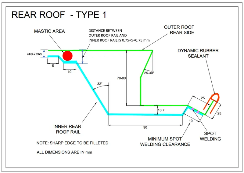
REAR ROOF RAIL:
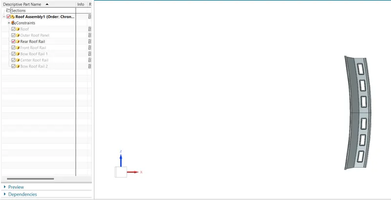
Rear roof rail is creating to length 80-100mm with proper draft angle. Give embosses on the sheet to ensure the enough strength for holding the roof structure. When considering the all parameters like length, width, sealants, rubber materials, wind shield to create the design properly.
Head room clearance = 120mm
Sheetmetal thickness = 0.75mm
Embosses height 2 < 3t
Radius = (3mm or 5mm)
MASTER SECTION FOR BOW ROOF RAIL:
BOW ROOF:
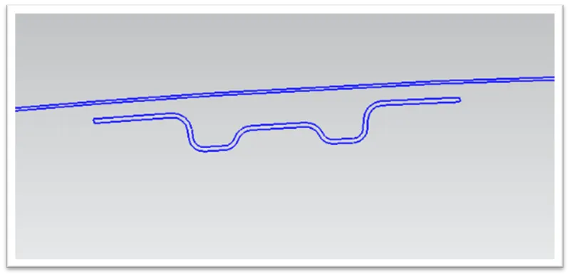
The bow roofs are given to the improve the torsional stiffness and load bearing capacity of the roof structure. When number of bow roofs are given by the roof dimension. Longer the roof area we have to give the more bow roof to the structure.
Positioning of the bow roofs are decided by the curvature study. The Heat distortion and Snow load criteria are checked to analyze the bow roof position by various condition.
We also give the Mastic area for fixing the Bow roof to the roof outer. Each mastic sealants are having 80mm circular effective area of surroundings. Thickness of the Bow roof is 0.75mm.
MASTER SECTION FOR REINFORCEMENT CENTER ROOF RAIL:
REINFORCEMENT CENTER ROOF RAIL:
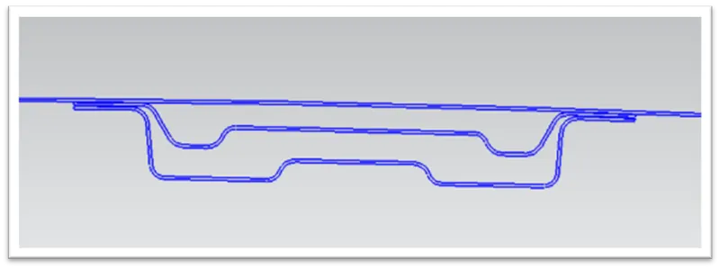
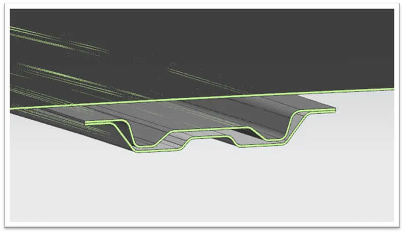
Reinforcement Center roof rail is effective support to the flat area structure roof. Because of center area of roof is more susceptible to failure under action of load. Usually, Reinforcement center roof rails are fixed at the center of the roof for connecting to the B – Pillar support structure, it will used for roll-over test.
Center bow roof and reinforcements are placed at the center of the roof structure. They two are connecting to help of spot - welding operation. Thickness of the Reinforcement center roof rail is 0.75mm.
MASTIC SEALANTS OF ROOF:
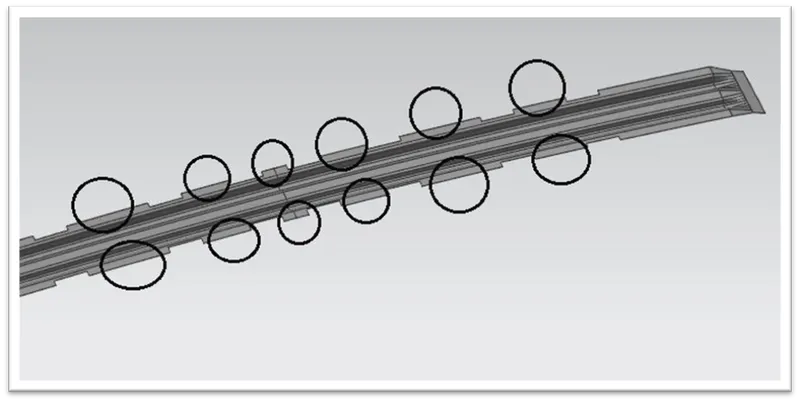
The Mastic sealant or the Mastic point is an elastic compound that behaves like a rubber. The mastic sealants are applied at the many places like roof outer to front roof rail, rear roof rail, bow roof and reinforcement center roofs. They help the roof outer panel to come back to its original shape after it gets deformed. The mastic has an influence area of 80mm.
It will give the three methods in one operation, it fills the gap between the two or more substrates, it forms a barrier through the physical properties of the sealant itself, and by adhesion to substrates.
CURVATURE STUDY ON THE ROOF:
- Heat Distortion
- Snow Load
HEAT DISTORTION:
The heat distortion study the plays an important role in Sheetmetal application. Heat distortion is temperature limit above which material cannot be used for structural application. This study is useful to fin the where the material starts to soften when exposed to a fixed load at elevated temperature. In order to avoid the bending, damage to the roof based on the heat distortion temperature. This study will provide the which position of the bow roof give enough strengthen to roof.
Bow Roof Prediction Formula:
HEAT DISTORTION CRITERIA:
W = [1.73 x 10^(-3) x L] + [1.85 x 10^(-8) x (R^2)/2] + [1.10 x 10^(-3) x I]-2.68
Judgement Condition: OK<2.7>3.1
Where,
L= Roof Length in X- direction [mm](Roof Dimension in 0-Y)
R = Roof curvature
R = 2(RX*RY)/(RX+RY)
RX = X Curvature
RY = Y Curvature
t = Roof plate thickness [mm]
I = Bow roof span [mm]
Thickness for the Roof(t):
Roof Outer Panel, t= 0.75mm
Front Roof Rail, t = 0.75mm
Rear Roof Rail, t = 0.75mm
Bow Roof Rail Front, t = 0.75mm
Bow Roof Rail Rear, t = 0.75mm
Reinforcement roof rail, t = 0.75mm
Procedure to measure the parameters:
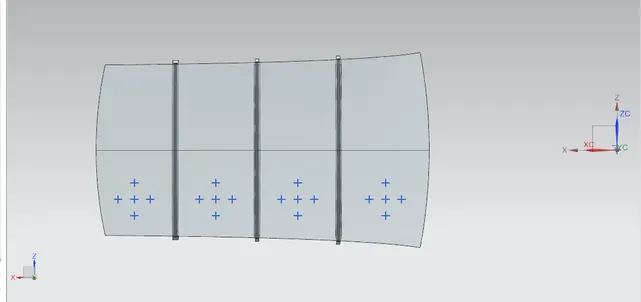
a) On plane parallel to the top plane draw sketch in which 0Y line is offset by 300 mm.
b) Draw lines perpendicular to 0Y line passing through point exact midpoint of the two adjacent parts (e.g. midpoint between front rail and bow roof 1)
c) Offset these reference lines on both sides by 100 mm
d) Mark intersection points of reference line and 100 mm offset lines.
e) These reference points are then projected on to roof outer panel surface to create curves.
f) Take all necessary measurements required to calculate W value as per mentioned formula.
To Find Rx and Ry:
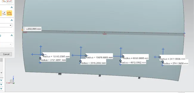
|
Roof Rail Span From |
L (mm) |
Rx (mm) |
Ry (mm) |
R |
t (mm) |
l (mm) |
W |
Result |
|
FR- Bow1 |
2032.0905 |
5741.5658 |
2411.9096 |
3396.8674 |
0.75 |
534.02 |
1.6984 |
OK |
|
Bow1-Bow2 |
2032.0905 |
4872.5952 |
6550.8808 |
5588.4549 |
0.75 |
464.45 |
2.1103 |
OK |
|
Bow2-Bow3 |
2032.0905 |
3916.2660 |
10676.6665 |
5730.5364 |
0.75 |
464.73 |
2.15 |
OK |
|
Bow3-RR |
2032.0905 |
3191.8891 |
15143.2386 |
522.4517 |
0.75 |
464.93 |
2.02 |
OK |
Snow load criteria calculations
Snow load criteria is useful to justify the bow roof rail position in snow fall regions. Due to snow fall snow will get collected on the top roof which will tend to bend the roof. Bow roof will be at such position which will provide more strength to roof against bending.
Qr = [Iy x t2] / [α x s x [(Rx + Ry)/2]2 x 10-8]
Note: The Qr value given over here is correct. There was a typo error in the formula given in the video.
Where
α = My x Lx2 x 10-12 , My = Y(Ly-Y)
Judgement condition = Qr ≥ 3.1
250 ≤ s ≤ 380
t = Roof plate thickness [mm]
Ly = Distance between the front and rear roof Rails on the Vehicle along with 0Y[mm]
Length of Roof panel with the center point between Roof rail Front /Rear as the reference point of the front and the rear.
Lx = Distance between the Left and Right end of the roof on the Roof BOW [mm]
Width of the roof panel exposed on the surface.
Y = Distance front Front Roof Rail to Roof BOW[mm]
s = Distance for which Roof BOW bears divided load [mm]
s = L1/2 + L2/2
Iy = Geometrical moment of inertia of Roof BOW (Y cross-section )[mm4]
Rx = Lateral direction curvature radius of roof panel Y cross-section on Roof BOW [mm]
Roof panel curvature Radius of the Length Lx in Front view
Ry = Longitudinal Direction curvature radius of the Roof panel X cross-section on Roof BOW [mm]
Roof panel X curvature radius of length s in Side view
Procedure to calculate necessary parameters:
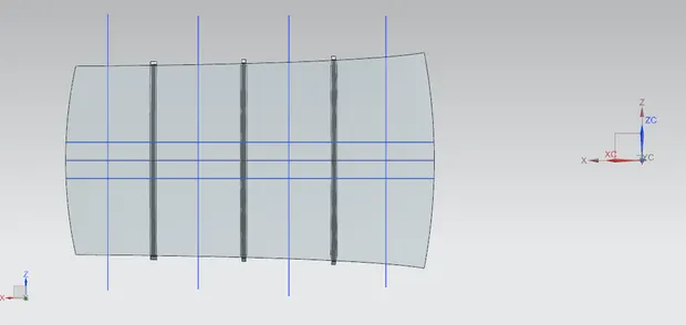
a) On plane parallel to the top plane draw sketch in which 0Y is projected along the direction perpendicular to top plane
b) Draw lines perpendicular to 0Y line passing through point exact midpoint of the two adjacent parts (e.g., midpoint between front rail and bow roof 1)
c) Offset these reference lines on both sides by 100 mm
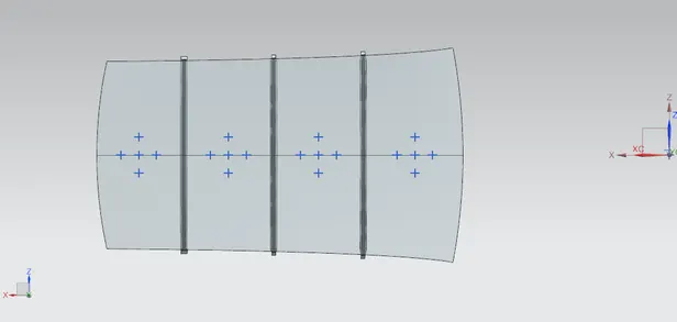
d)Mark intersection points of reference line and 100 mm offset lines.
e) These reference points are then projected on to roof outer panel surface to create curves.
f) Take all necessary measurements required to calculate QR value as per mentioned formula.
To Find Rx & Ry:
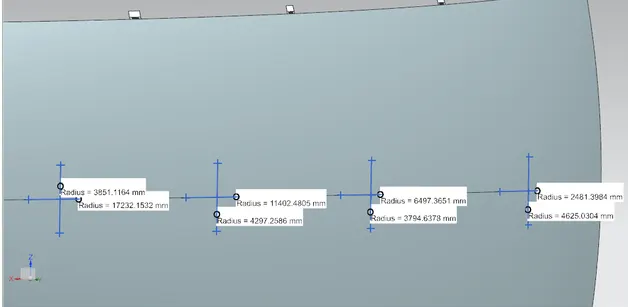
|
Roof Rail Span From |
Iy (mm^4) |
L1 (mm) |
L2 (mm) |
Lx (mm) |
Ly (mm) |
Rx (mm) |
Ry (mm) |
t (mm) |
y (mm) |
s |
a |
Qr |
Result |
|
FR- Bow1 |
5.570465948 |
1468.4598 |
499.3084 |
1140.9571 |
2032.0905 |
4625.0904 |
2481.3984 |
0.75 |
1462.4598 |
983.8742 |
1.08 |
0.02 |
NG |
|
Bow1-Bow2 |
5.558227306 |
499.3084 |
499.3304 |
1083.7781 |
2032.0905 |
3794.6378 |
6497.3651 |
0.75 |
499.3084 |
499.3194 |
0.89 |
0.0262 |
NG |
|
Bow2-Bow3 |
5.534369477 |
499.3304 |
1479.7092 |
1057.2984 |
2032.0905 |
4297.2586 |
11402.4808 |
0.75 |
499.3304 |
989.5198 |
0.85 |
0.006 |
NG |
MOMENT OF INERTIA:
BOW ROOF RAIL 1:
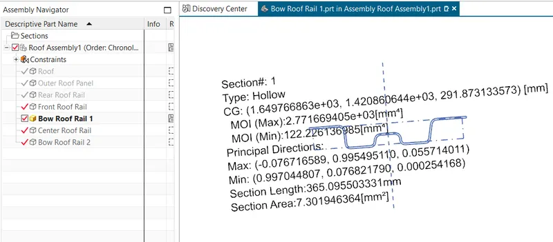
Moment of inertia maximum,( MAX) I max =2.771×10³ ( mm4)
Moment of inertia maximum ,( MIN) I min =122.226 ( mm4)
BOW ROOF RAIL 2
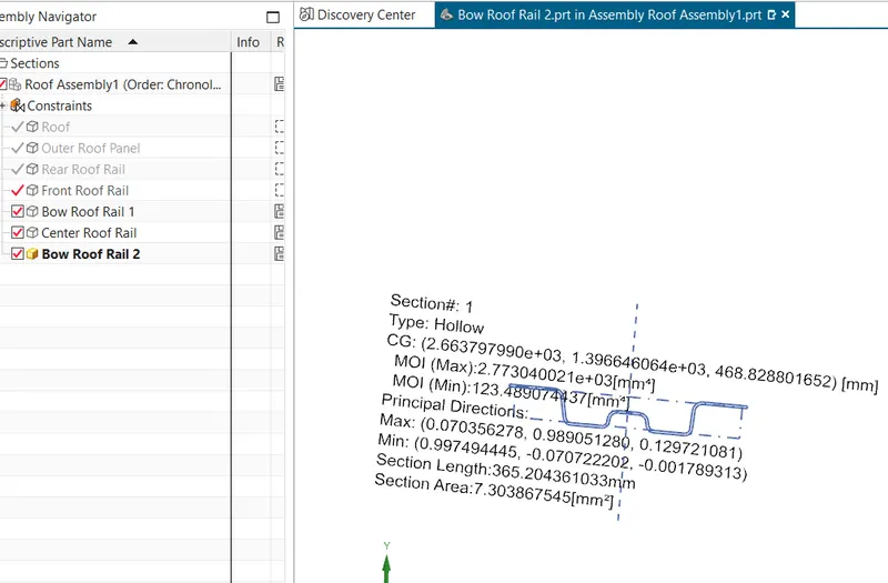
Moment of inertia maximum,( MAX) I max =2.773× 10^3 ( mm4)
Moment of inertia maximum ,( MIN) I min =123.489 ( mm4)
CENTRAL ROOF RAIL :
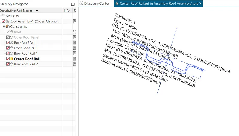
Moment of inertia maximum,( MAX) I max =4.889× 10^3 ( mm4)
Moment of inertia maximum ,( MIN) I min =211.020( mm4)
FRONT ROOF RAIL
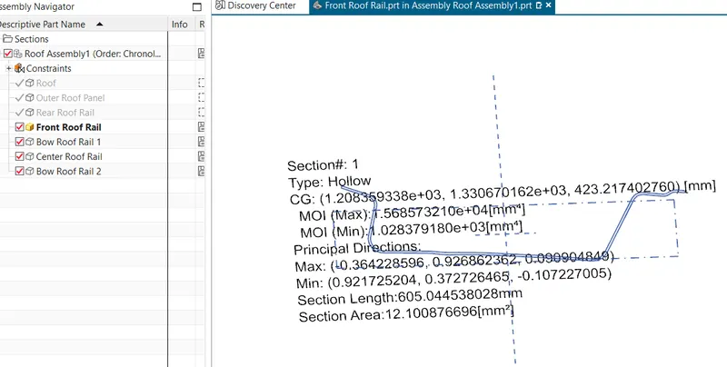
Moment of inertia maximum,( MAX) I max =1.56× 10⁴ ( mm4)
Moment of inertia maximum ,( MIN) I min =1.02× 10³( mm4)
REAR ROOF RAIL
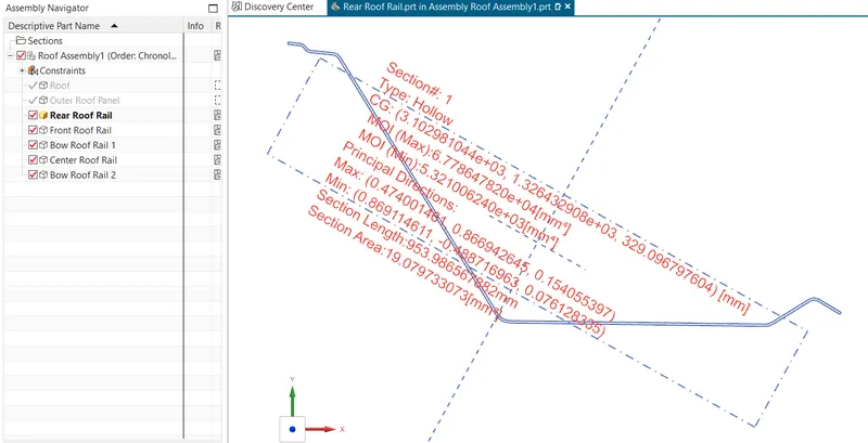
Moment of inertia maximum,( MAX) I max =6.77x10⁴ ( mm4)
Moment of inertia maximum ,( MIN) I min =5.32× 10³( mm4)
DRAFT ANALYSIS :
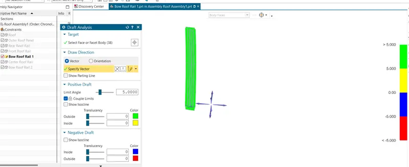
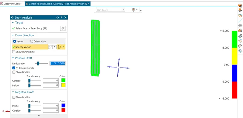
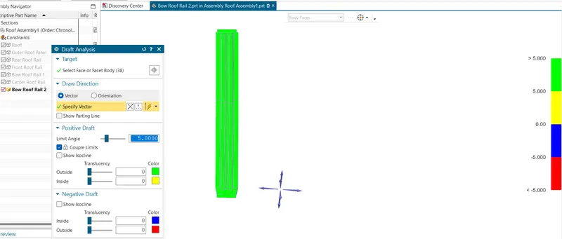
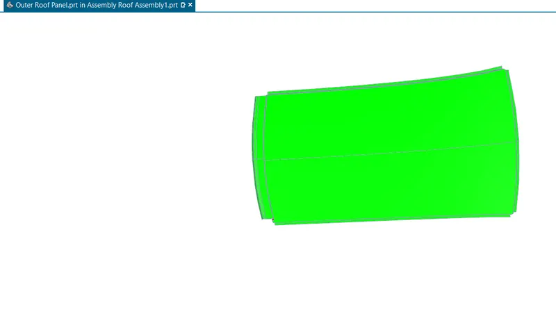
The Draft Analysis command enables you to detect if the part you drafted will be easily removed. This type of analysis is performed based on color ranges identifying zones on the analyzed element where the deviation from the draft direction at any point, corresponds to specified values.
Minimum draft angle of 70 is considered for analysis . green colour infer on the parts that all face along the tooling direction has positive draft angle greater than 70 and passed in analysis
DRAFT ANALYSIS FOR FRONT REAR ROOF RAIL :
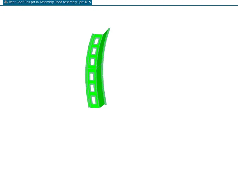
DRAFT ANALYSIS FOR FRONT ROOF RAIL :
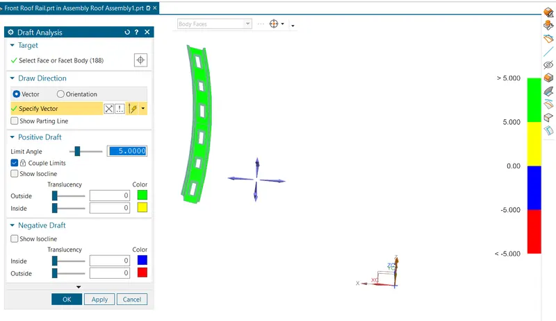
DRAFT ANALYSIS FOR BOW ROOF RAIL 1:
DRAFT ANALYSIS FOR CENTRAL ROOF RAIL :
DRAFT ANALYSIS FOR BOW ROOF RAIL - 2:
OUTER ROOF PANEL :
ROOF IMAGES :
TOP VIEW :
SIDE VIEW :
ISOMETRIC VIEW :
CONCLUSION :
Hence the roof , front roof rail, bow roof rails , central roof rail and the rear roof rail is designed by following the master sections and the moment of inertia and draft analysis are carried out to check feasibility manufacturing.