Roof Design
ROOF DESIGN OBJECTIVE :
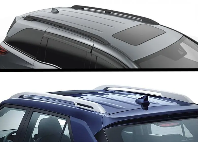
The objective of this project is to design car roof with essential flanges and reinforcements like ditch area , front roof rail , bow roofs, central roof rail and rear roof rail for the the given styling surface Perform a curvature study on the roof and perform the calculations…
ROOF CRUSH TEST :
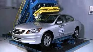
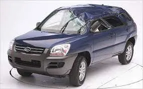
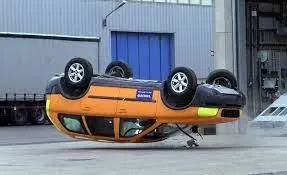
Roof crush test is the design given by the IIHS ( insurance institute of highway safety ).After analyzing the many accidents IIHS has then fixed some regulations , that how to perform the crush test .
This gives the rating based up on this test . For this they consider two points while giving the rating
- How fast the car can reforms to its original shape after the roll over and
- How deep is the protrusion after the roll over.
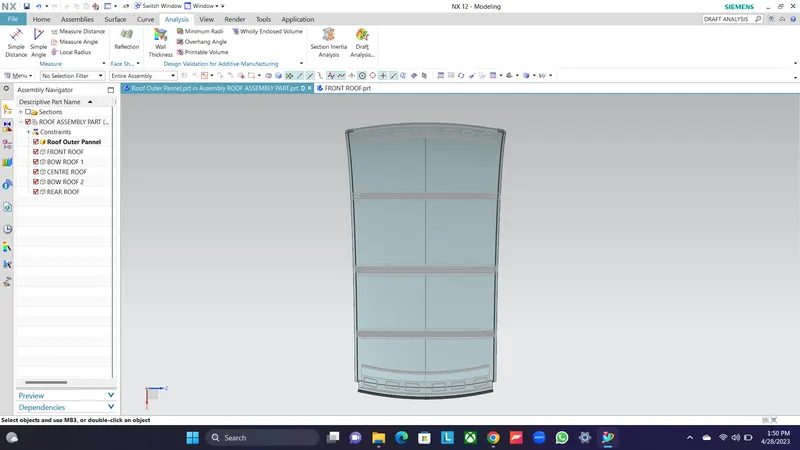
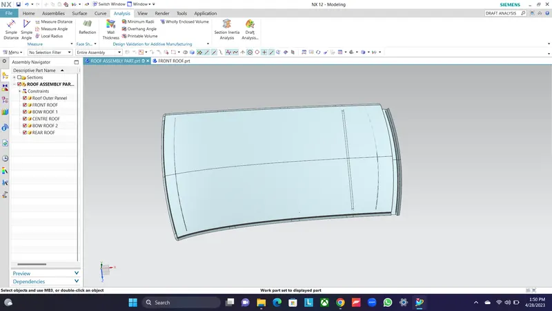
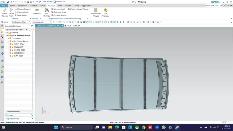
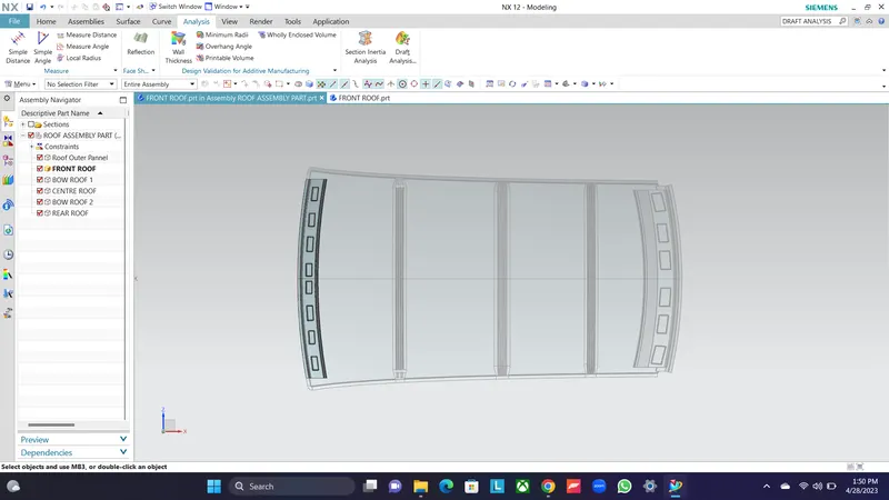
ASSEMBLY OF DESIGNED ROOF IN NX-CAD
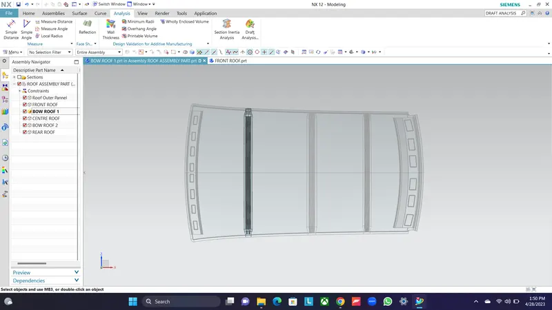
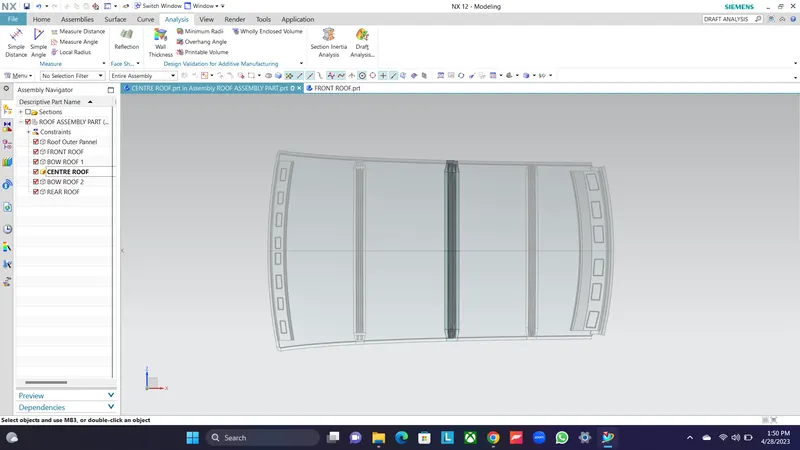
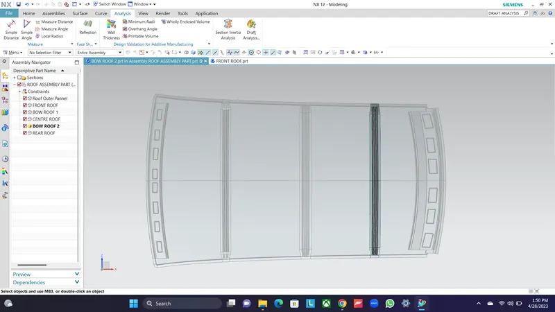
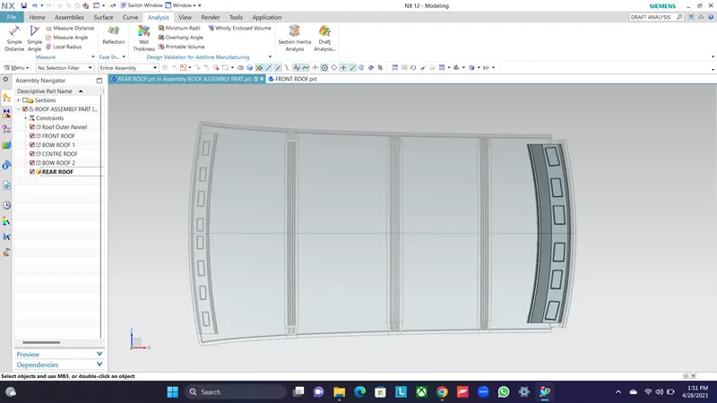
Reinforcement of Roof:
1) Front Roof Rail
2) Bow Roof Rail
3) Center Roof Rail
4) Rear roof Rail
FRONT ROOF RAIL:
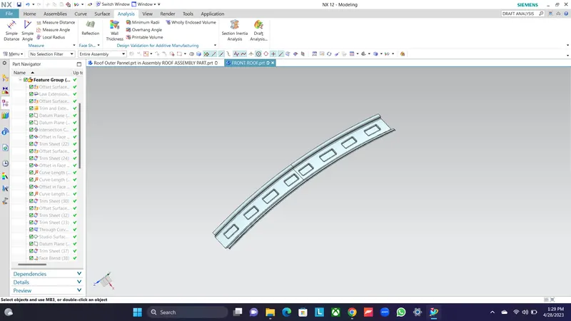
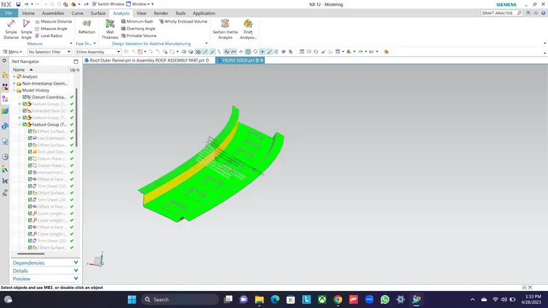
Front roof rail is provided at the front end of the roof to provide strength to that area of roof, while designing this part we should maintain the visibility and headroom clearance. Embosses are created to strengthen the front roof rail.
REAR ROOF RAIL:
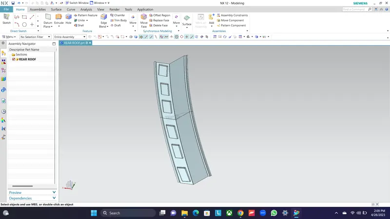
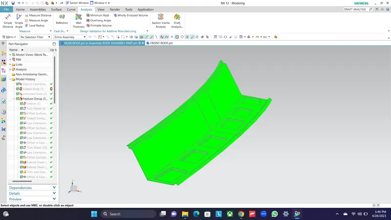
It is provided at the rear part of the roof and it is joined with the outer roof by spot welding. We should take consideration of rear headroom and visibility criteria while desiging this. Embosses are created to strengthen the rear roof rail.
BOW ROOF 1:
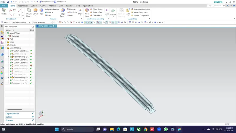
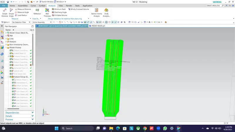
It is provided to give strength to the roof at that areas,it can be created at any number depending upon the length of the roof. Mastic points are provided to join this bow roofs to the outer panel.
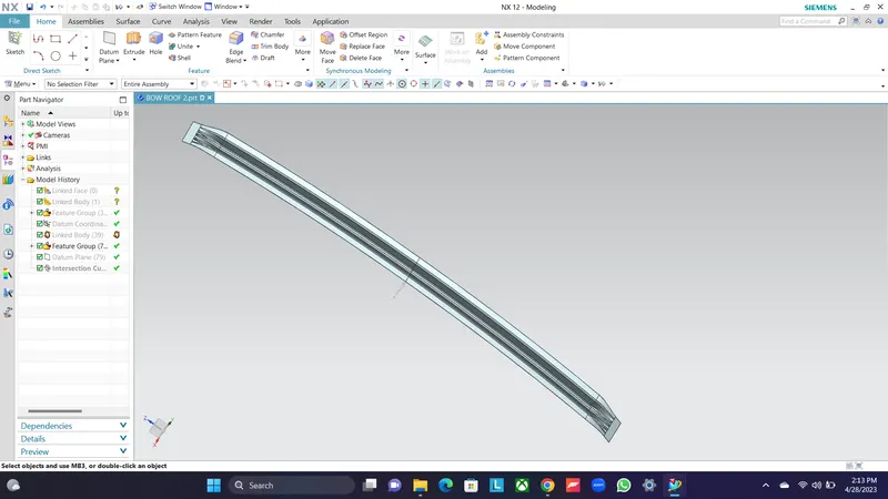
BOW ROOF 2:
CENTRE ROOF:
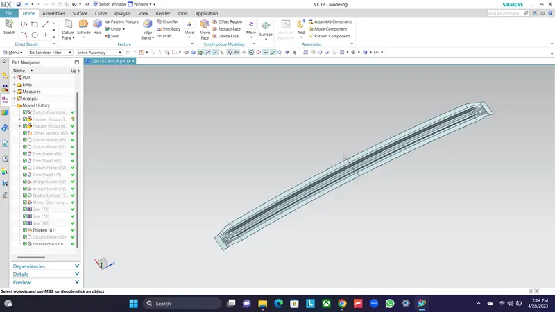
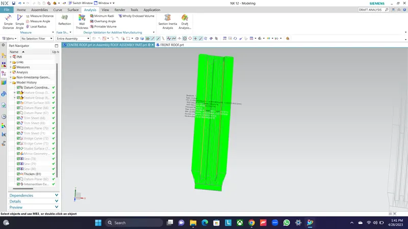
It is provided at the center of the roof to strengthen that area and it is joined to the outer panel by mastic.
HEAT DISTORTION CALCULATION:
This calculation is performed to check the strength of the roof at a certain load with a certain temp. This study will predict the position of bow roofs.
W = [1.73 x 10^(-3) x L] + [1.85 x 10^(-8) x (R^2)/t] + [ 1.10x10^(-3) x l] - 2.68
Where,
L = Roof Length in X-Direction[mm](Roof dimension in 0-Y)
R = Roof curvature
R = 2(Rx*Ry)/(Rx+Ry)
Rx = X curvature
Ry = Y curvature
t = Roof plate thickness [mm]
l = Bow Roof Span [mm]
Judgement Condition - OK<2.7
| ROOF RAIL | Rx | Ry | Rx*Ry |
Rx+Ry |
R | L | T | I | W | RESULT |
| FRONT ROOF -BOW 1 | 5731.22 | 2661.10 | 15251406.9 | 8392.32 | 3634.6 | 2062 | 0.75 | 372 | 1.6134 | P |
| BOW 1 -CENTRE BOW | 4790.311 | 6924.410 | 33170070.5 | 11714.71 | 5662.9 | 2062 | 0.75 | 484 | 1.9238 | P |
| CENTRE BOW - BOW 2 | 3843.60 | 11267.90 | 433093004.8 | 15111.5 | 5731.96 | 2062 | 0.75 | 410 | 2.311 | P |
| BOW2 -REAR ROOF | 3260.2 | 14113.88 | 46013810.8 | 17374.1 | 5296.7 | 2062 | 0.75 | 200 | 1.7064 | P |
SNOW LOAD CALCULATION:
Qr = [Iy x t2] / [α x s x [(Rx + Ry)/2]2 x 10-8]
Where,
α = My x Lx^2 x 10^-12, My = Y(Ly-Y)
Judgement condition = Qr ≥ 3.1
250 ≤ s ≤ 380
t = Roof plate thickness [mm]
Ly = Distance between the front and rear roof Rails on the Vehicle along with 0Y[mm]
Length of Roof panel with the center point between Roof rail Front /Rear as the reference point of the front and the rear.
Lx = Distance between the Left and Right end of the roof on the Roof BOW [mm]
Width of the roof panel exposed on the surface.
Y = Distance front Front Roof Rail to Roof BOW[mm]
s = Distance for which Roof BOW bears divided load [mm]
s = L1/2 + L2/2
Iy = Geometrical moment of inertia of Roof BOW (Y cross-section) [mm4]
Rx = Lateral direction curvature radius of roof panel Y cross-section on Roof BOW [mm]
Roof panel curvature Radius of the Length Lx in Front view
Ry = Longitudinal Direction curvature radius of the Roof panel X cross-section on Roof BOW [mm]
| SECTION | IY | T | Y | LX | LY | MY | α | L1 | L2 | S | Rx | Ry | Qr | RESULT |
| FRONT ROOF -BOW 1 | 445.14 | 0.75 | 385 | 2062 | 1119.23 | 654896.235 | 0.79856235 | 383 | 485.5 | 415.5 | 4689.5 | 2409.32 | 6.089472 | P |
|
BOW 1-CENTRE ROOF |
710.56 | 0.75 | 458 | 2062 | 1256.23 | 615435.58 | 0.76584212 | 466 | 465.2 | 436.55 | 37775.9 | 6102.89 | 2.525986 | F |
| CENTRE ROOF-BOW 2 | 554.89 | 0.75 | 423 | 2062 | 5623.12 | 687452.31 | 0.70256300 | 589.2 | 411.2 | 423.78 | 4263 | 10917.6 | 5.385466 | P |
| BOW2-REAR ROOF | 258.98 | 0.75 | 410 | 2062 | 4589.23 | 589752.15 | 0.66584822 | 489 | - | - | 3951.3 | 16673.6 | - | - |
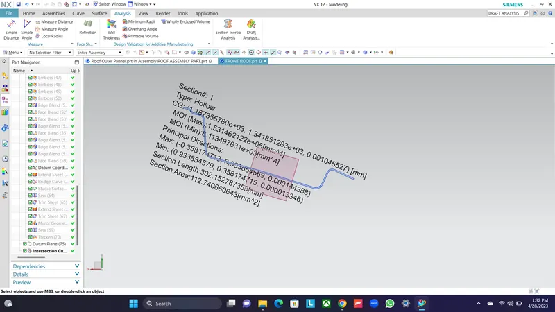
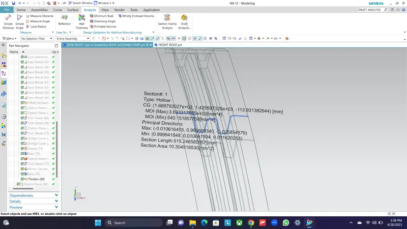
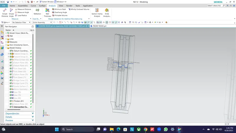
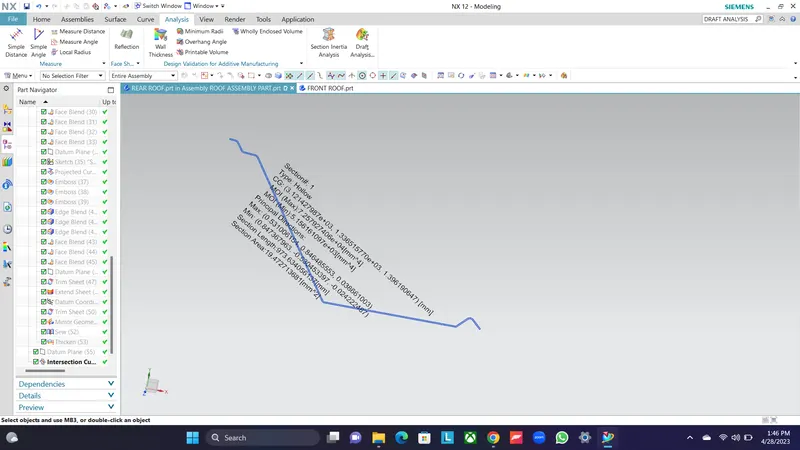
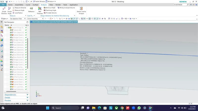
Moment of inertia:
ROOF FRONT PART:
BOW ROOF :
CENTRE ROOF :
:
REAR ROOF:
ROOF OUTER PANNEL:
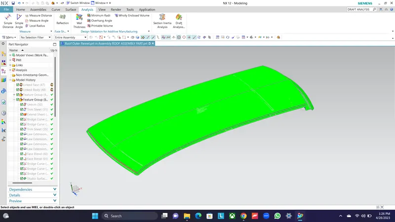
DRAFT ANALYSIS:
ROOF OUTER PANNEL:
ROOF FRONT :
BOW ROOF:
CONCLUSION:
We were successfully able to design the roof with all the roof rails for better support and strength. We designed it so as to satisfy the norms and regulations by calculating the heat distortion criteria and the snow load critera. While doing this we also understood about the methodology behind designing the roof of the car and what all we take into consideration while designing.