Roof Design
ROOF DESIGN
The conventional task of the roof panel is that of compartment shielding, passenger protection and connection of body sides, front and roof cross members. In case of roll over, compartment integrity is provided by the compartment frames, whilst the roof target is only to avoid the ejection of passengers, providing protection against hard local contact.
Correspondingly a wide selection of suitable materials are available: Steel, aluminium, thermosetting plastic sheet, glass. In case of steel grade FEP04, the usual thickness is in the range of 0.65 to .85 mm. In all cases, any roof panel material requires braces to prevent panel flexing and vertical waviness, commonly known as oil canning: for this purpose light steel bows are introduced, which are welded or riveted or screwed to the body side and bounded to roof panel by smooth flexible adhesives such as butyl mastic (in order to avoid sink marks on roof surface), mainly providing a damping effect.
Another task of roof bows is to support the interior roof liner which requires a number of fittings both in central and boundary areas to avoid deflections and vibrations. Fittings are usually plastic clips or velcro strips. Some roof liners, mostly on less expensive vehicles are bonded directly to roof panel.
Fig 1:- Car Roof
Types of Roof:-
1. Car Sunroof
2. Car Moonroof
3. Car Panoramic Roof
1. Car Sunroof:-
Sunroofs can be opened and closed using an electronic system. Sunroofs cars allow light, fresh air, or even both to enter the car cabin It’s easier to imagine sunroof as a window on the car roof. Commonly, sunroofs carry two types of panels made from the same solid metal used for the car ceiling exterior and can be pulled by hand to open the glass panel. Above it is colored glass which can be tilted backward to allow air from outside to enter the cabin.
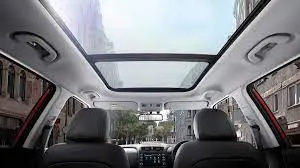
Fig 2:- Car Sunroof
2. Car Moonroof:-
Moonroofs are actually one type of sunroofs. However, the material and uses are different. Moonroofs are made to allow the car driver and passengers to enjoy the outside view at night without having to get out of the car or open the car roof. Moonroofs have colored glass panels that allow light and air to enter without having to shift the visor. However, lately, moonroofs are also equipped with a metal coating to keep the sunlight from entering directly into the cabin during the day. Usually, the moonroof opens just slightly compared to the sunroof, so that air and light can enter into the cabin. However, there are a number of car manufacturers who now make moonroofs wide open just like sunroofs.
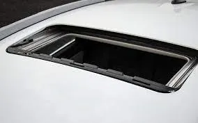
Fig 3:- Car Moonroof
3. Car Panoramic Roof:-
This type of car roof is generally similar to the moonroofs, which has a large glass panel stretching across the roof, right above the first to the second rows. The panoramic roofs can open wider compared to the moonroofs in general. Panoramic roofs also have coating blinds to keep the cabin cool when the glass layer is closed, but the view in the sky is still visible. The panoramic roofs offer a different look to the car’s interior so that it becomes more luxurious.
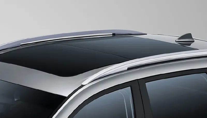
Fig 4:-Car Panoramic Roof
Roof Design:_
To design the roof with their essential component or ditch area for the given roof styling surface.
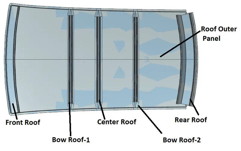
Fig 5:-Car Roof
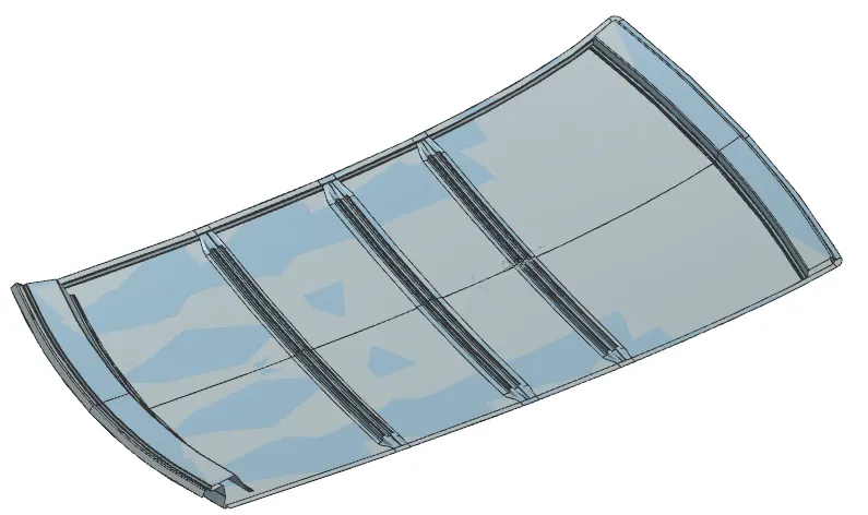
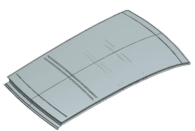
Fig 6:- Roof View Fig 7:- Roof View
Different types of reinforcements that the car has are :
1. Front roof rail
2. Bow roofs
3. Central roof rail
4. Rear roof rail
5. Roof Outer Panel
1. FRONT ROOF RAIL :-
Front roof rail is the one which joins the wind shield glass, body side outer and the inner panel also. Here the front roof rail is designed based up on the master saection given.
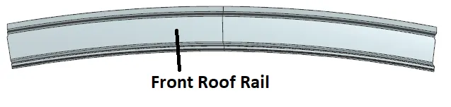
Fig 8:- Front Roof Rail
2. Bow Roofs:-
The bow roofs are give to improve the torsional stiffness and load bearing capacity of the roof structure. The number of bow roof present is depends on the overall size of the roof. Presently in this project two bow roofs are added which as given below.
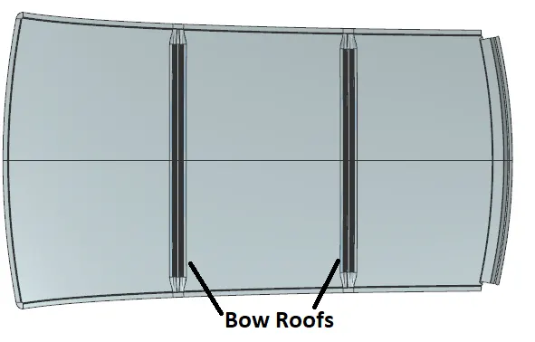
Fig 8:- Bow Roof Rail
JOINING PROCESS :
Mastics are introduced between the roof outer panel and the reinforcements for joining. where ever the mastic area introduced there is remarkable improve of the strength, spot welding is also introduced to join the reinforcements and the outer panel.
3. Central roof rail:-
Central roof rail helps in providing effectively support to the flat area of the roof as it is more susceptible to failure under the action of load. Generally central roof rail is placed at the center of the roof which is connected to the B-pillar support structure. This central roof rail helps in adding the strength to the roof during the rool-over test.

Fig 9:- Center Roof Rail
4. Rear roof rail:-
Rear roof rail is the one which joins the back door and the body side outer
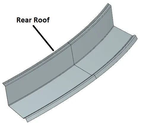
Fig 10:- Rear Roof Rail
4. Roof Outer Panel:-
Its the outer panel to protect cabin passenger from veriable weather atmospheric condiation. Also on it mounted diffenrent rainforcement as like Front roof, bow roof's, center roof & rear roofs.
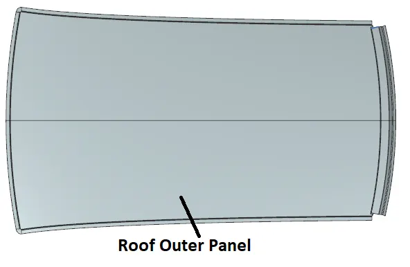
Fig 11:- Roof Outer panel
Design consideration for a roof:-
- Visibility criteria
- Head clearance
- Curvature study
- Heat distortion and snow load criteria
- Draft analysis
Roof Crush Test :-
Roof crush test is the design given by the IIHS ( insurance institute of highway safety ). After analyzing the many accidents IIHS has then fixed some regulations, that how to perform the crush test. IIHS gives the rating based up on this test. For this they consider two points while giving the rating.
- How fast the car can reforms to its original shape after the roll over and
- How deep is the protrusion after the roll over
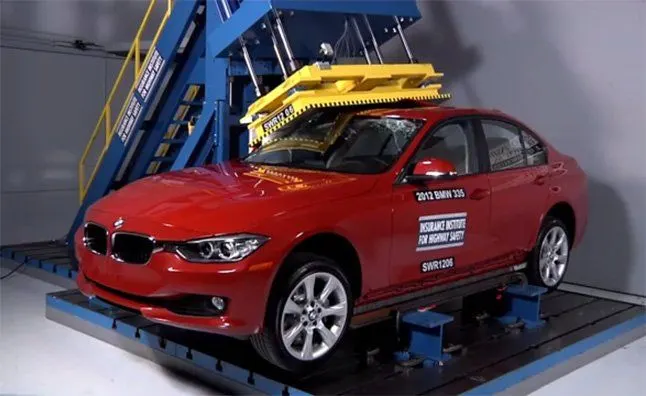
Fig 12:- Roof Crush Test
Goal of Roof Crush Test :-
To minimize the protrusion into the occupant compartment, so that the seat belts and air bags can do there job in protecting the occupant.
Condiations to follow Roof Crush Test :-
There are two conditions that should be followed for the roof crush test, they are
Initial Condiation:-
- Close and lock all the doors
- Close all the windows
Second Condiation:-
Fix the body sill or chassis frame on a hard lever surface horizontally.
Method of applyng force:-
The load is applied in such a way that 50 is tilted from the front end to the rear end and the load will be in 1800 mm in length and 750 mm in width. The load is applied at the position of 250 from the flatness of the roof. The load is applied on the roof for almost 120 sec and the crush speed at which the load applied is 13 mm/sec or less than that.
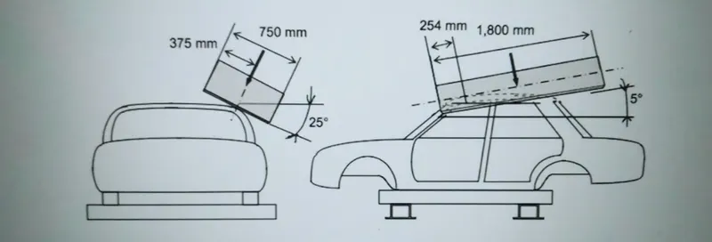
Fig 13:- Roof Crush Test
Result:-
If the displacements goes above the requirements level then we have to increase the bow roof thickness or add more mastics points to increase the strength . the stronger the roof the better it can protect the occupants in the roll over crashes.
Heat distortion study on the roof:-
The heat distortion study plays a major role in sheet metal usage. Heat distortion temperature is a temperature limit above which the Material cannot be used for the structural applications. This study is used to predict the heat distortion temperature at where the material starts to soften when exposed to a fixed load at elevated temperature. In order to avoid bending or damages on the roof, based on the heat distortion temperature, this study will predict the bow roof position which helps to strengthen the roof.
BOW – Roof prediction Formula
W = [1.73 x 10^(-3) x L] + [1.85 x 10^(-8) x (R^2)/t] + [ 1.10x10^(-3) x l] - 2.68
Where
L = Roof Length in X-Direction[mm](Roof dimension in 0-Y)=2028.94 mm
R = Roof curvature
R = 2(Rx*Ry)/(Rx+Ry)
Rx = X curvature
Ry = Y curvature
t = Roof plate thickness [mm]=0.75 mm
l = Bow Roof Span [mm]
Judgement Condition:-
OK< 2.7> 3.1
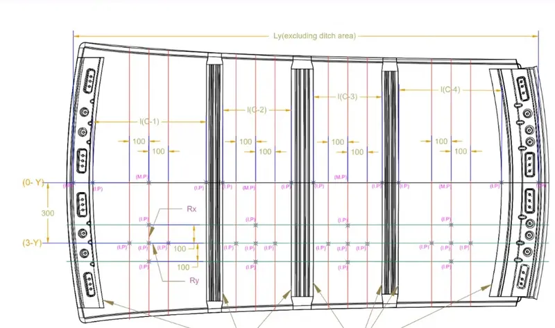
Fig 14:- Heat distortion calculation
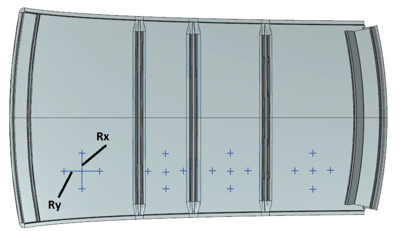
Fig 15:- Heat distortion calculation

From the above table it can be concluded that all values of w<2.7 and also not w>3.1 so thus infers that current positioning of bow row are good in state as per design and found ok.
Snow load criteria:-
This test is done to know how is the roof behaving when there is a snow over. Normally due to the snow weight the dent will happen. But the roof should be designed in such a way that when the snow is removal the roof should go it its original position.This is the basic requirements for snow load criteria.
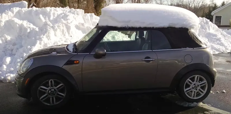
Fig 16:- Snow load vehicle
Snow Load Prediction Formula
Qr = [Iy x t2] / [α x s x [(Rx + Ry)/2]2 x 10-8]
Note: The Qr value given over here is correct. There was a typo error in the formula given in the video.
Where,
α = My x Lx2 x 10-12 , My = Y(Ly-Y)
t = Roof plate thickness [mm]
Ly = Distance between the front and rear roof Rails on the Vehicle along with 0Y[mm]
Length of Roof panel with the center point between Roof rail Front /Rear as the front and rear reference point.
Lx = Distance between the Left and Right end of the roof on the Roof BOW [mm]
The width of the roof panel is exposed on the surface.
Y = Distance front Front Roof Rail to Roof BOW[mm]
s = Distance for which Roof BOW bears divided load [mm]
s = L1/2 + L2/2
Iy = Geometrical moment of inertia of Roof BOW (Y cross-section )[mm4]
Rx = Lateral direction curvature radius of roof panel Y cross-section on Roof BOW [mm]
Roof panel curvature Radius of the Length Lx in Front view
Ry = Longitudinal Direction curvature radius of the Roof panel X cross-section on Roof BOW [mm]
Roof panel X curvature radius of length s in Side view
Judgment condition
Qr ≥ 3.1
250 ≤ s ≤ 380
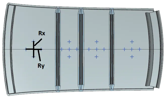
Fig 17:- Snow load calculation
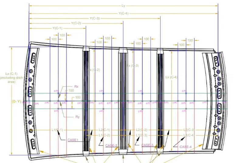
Fig 18:- Snow load calculation
CALCULATIONS:-

It is observed from the values that obtained values of QR > 3.1
Section analysis:
Section moment of inertia is used to predict the amount of deformation and deflection of a part. A higher moment of inertia is preferable as it reduces the amount of deflection for a given force. The thickness of the part and addition of flanges and embosses increase the section inertia of the part. Here the master sections of the roof and roof rails and their section analysis are given.
Front Roof Rail
Create an intersection curve with the help of the plane and select the front roof
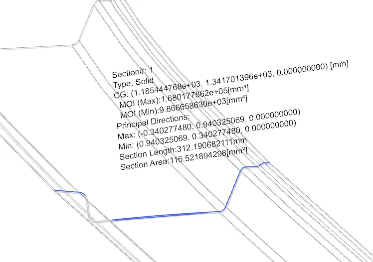
Fig 19:- Front Roof Rail
Moment of inertia maximum,( MAX) I max =1.68×10⁵ ( mm4)
Moment of inertia maximum ,( MIN) I min =9.68×10³( mm4)
Bow Roof 1
Create an intersection curve with the help of the plane and select the bow roof 1
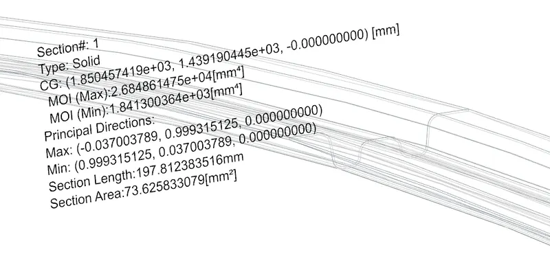
Fig 20:- Bow Roof 1
Moment of inertia maximum,( MAX) I max =2.68×10⁴ ( mm4)
Moment of inertia maximum ,( MIN) I min =1.84×10³ ( mm4)
Central Roof Rail:-
Create an intersection curve with the help of the plane and select the Central Roof

Fig 21:- Central Roof Rail
Moment of inertia maximum,( MAX) I max =3.75×10⁴ ( mm4)
Moment of inertia maximum ,( MIN) I min =2.88×10³ ( mm4)
Bow Roof 2
Create an intersection curve with the help of the plane and select the bow roof 2
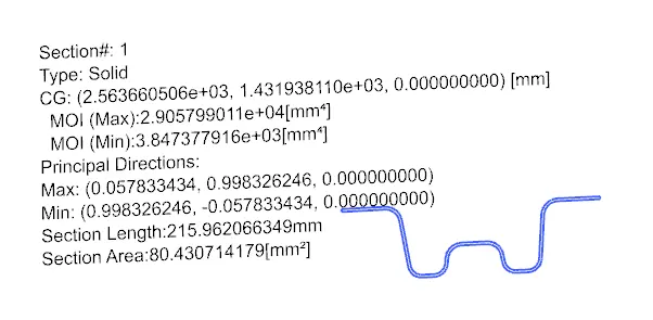
Fig 22:- Bow Roof 2
Moment of inertia maximum,( MAX) I max =2.90x10⁴ ( mm4)
Moment of inertia maximum ,( MIN) I min =3.84×10³( mm4)
Rear Roof Rail
Create an intersection curve with the help of the plane and select the Rear Roof Rail
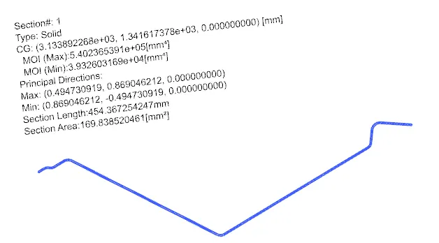
Fig 23:- Rear Roof Rail
Moment of inertia maximum,( MAX) I max =5.40x10⁵ ( mm4)
Moment of inertia maximum ,( MIN) I min =3.93x10⁴( mm4)
Draft Analysis:-
The Draft Analysis command enables you to detect if the part you drafted will be easily removed. This type of analysis is performed based on color ranges identifying zones on the analyzed element where the deviation from the draft direction at any point, corresponds to specified values.
Minimum draft angle of 70 is considered for analysis. Green colour infer on the parts that all face along the tooling direction has positive draft angle greater than 70 and passed in analysis.
Draft Analysis for Front Roof Rail
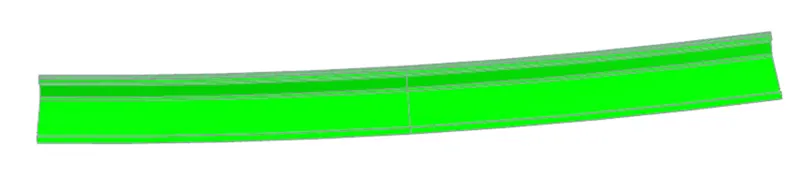
Fig 24:- Draft Analysis for Front Roof Rail
Draft Analysis for Bow Roof Rail-1
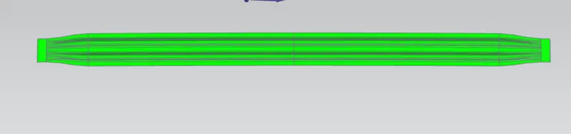
Fig 23:- Draft Analysis for Bow Roof Rail-1
Draft Analysis for Central Roof Rail
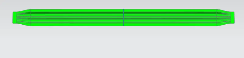
Fig 24:- Draft Analysis for Central Roof Rail
Draft Analysis for Bow Roof Rail-1

Fig 25:-Draft Analysis for Bow Roof Rail-1
Draft Analysis for Front Rear Roof Rail:-
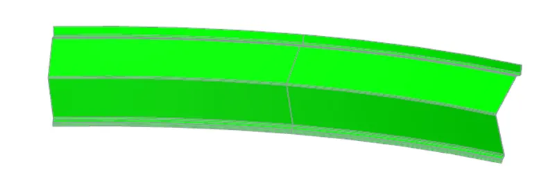
Fig 26:- Draft Analysis for Front Rear Roof Rail:-
ROOF IMAGES
TOP VIEW
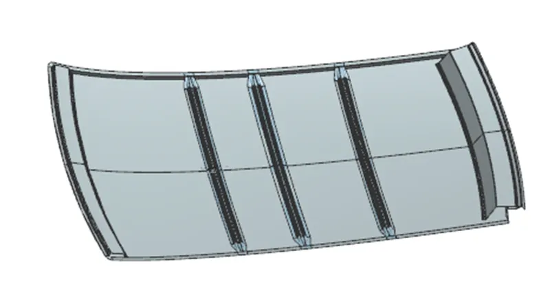
Fig 27:-TOP VIEW
SIDE VIEW

Fig 28:-SIDE VIEW
ISOMETRIC VIEW
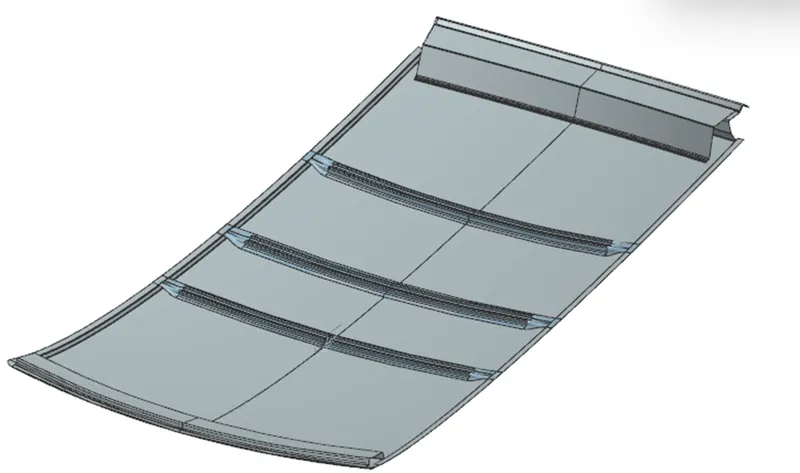
Fig 29:-ISOMETRIC VIEW
CONCLUSION
Hence the roof, front roof rail, bow roof rails, central roof rail and the rear roof rail is designed by following the master sections and the moment of inertia and draft analysis are carried out to check feasibility manufacturing.