Roof Design
Aim:Utilising the provided skin data for the roof in accordance with the standards for hear distortion and snow load, the front, rear, and bow roof rails for the cars' roofs are designed.
Roof
The area of an automobile that is located above the passenger compartment and shields the occupants from the sun, wind, rain, and other environmental factors is known as the roof or car top. A roof is a structure that is located above the wind-shield glass and has reinforcements to help the building as a whole and to withstand external forces like snow.
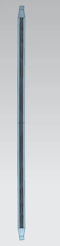
Designed Roof:
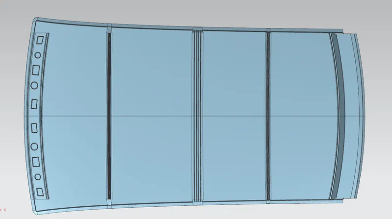
Components Of Roof
1.Front Roof Rail: The front roof rail is what connects the body side outer and inner panels as well as the wind shield glass. Here, the front roof rail is created using the provided master section.
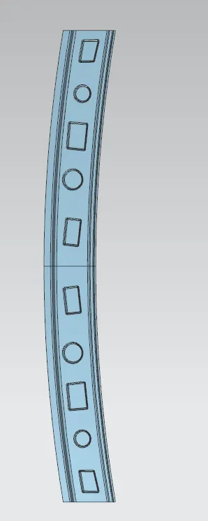
2.Rear Roof rail:The rear roof rail is the piece that connects the back door to the exterior body side.
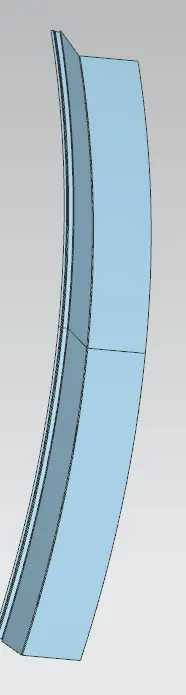
3.Central Roof Rail:The flat portion of the roof is more prone to failure due to the action of stress, hence a central roof rail aids in properly supporting it. The B-pillar support structure is connected to the central roof rail, which is typically located at the centre of the roof. During the roll-over test, this central roof rail adds strength to the roof.
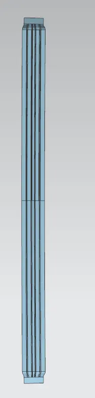
4.Bow Roofs : The purpose of bow roofs is to increase the roof structure's torsional rigidity and load carrying capacity. The amount of bow roofs that are present depends on the size of the roof as a whole.
Calculations
Heat Distortion Curvature Study:
The purpose of this study is to identify and forecast the heat distortion temperature at which a material begins to deteriorate when subjected to a fixed load. Therefore, based on this calculation, we will determine where the roof bows are located in order to prevent bending or damage to the roof.
W = [1.73 x 10^(-3) x L] + [1.85 x 10^(-8) x (R^2)/t] + [ 1.10x10^(-3) x l] - 2.68
Judgement Condition : OK< 2.7> 3.1
Where,
L = Roof Length in X-Direction[mm](Roof dimension in 0-Y)
R = Roof curvature
R = 2(Rx*Ry)/(Rx+Ry)
Rx = X curvature
Ry = Y curvature
t = Roof plate thickness [mm]
l = Bow Roof Span [mm] 3.5103949
| Bow posiotion | Rx | Ry | R | I | L | t | W | OK/NG |
| FR and 1st | 5634.52 | 3066.15 | 3971.25 | 451.17 | 2029.13 | .75 | 1.715 | OK |
| 1st and CTR | 4843.24 | 6624.42 | 5595.50 | 499.68 | 2029.13 | .75 | 2.15 | OK |
| CTR and 2nd | 4056.32 | 10591.7 | 5866 | 388.61 | 2029.13 | .75 | 2.1 | OK |
| 2nd and RR | 3434.12 | 14478.2 | 5551.47 | 360.69 | 2029.13 | .75 | 1.95 | OK |
Snow Load Criteria
This test is carried out to determine how the roof will function with snow on it. Typically, the dent will occur because of the weight of the snow. However, the roof must be made so that it returns to its original position after the snow is removed. These are the fundamental conditions for the snow load criteria.
Qr = [IY x t2] / [α x s x [(RX + RY)/2]2 x 10-8]
Where
α = My x L x2 x 10-12 , My = Y(Ly-Y)
Judgement condition = Qr ≥ 3.1
250 ≤ s ≤ 380
t = Roof plate thickness [mm]
Ly = Distance between the front and rear roof Rails on the Vehicle along with 0Y[mm]
Length of Roof panel with the center point between Roof rail Front /Rear as the reference point of the front and the rear.
Lx = Distance between the Left and Right end of the roof on the Roof BOW [mm]
Width of the roof panel exposed on the surface.
Y = Distance front Front Roof Rail to Roof BOW[mm]
s = Distance for which Roof BOW bears divided load [mm]
s = L1/2 + L2/2
Iy = Geometrical moment of inertia of Roof BOW (Y cross-section )[mm4]
Rx = Lateral direction curvature radius of roof panel Y cross-section on Roof BOW [mm]
Roof panel curvature Radius of the Length Lx in Front view
Ry = Longitudinal Direction curvature radius of the Roof panel X cross-section on Roof BOW [mm]
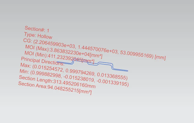
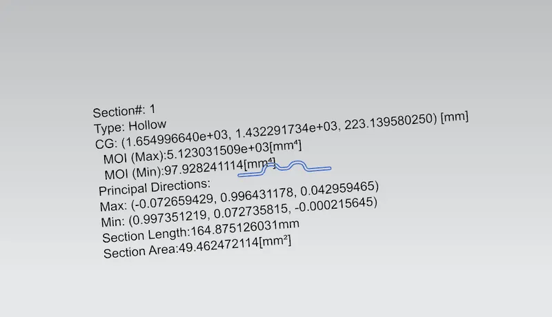
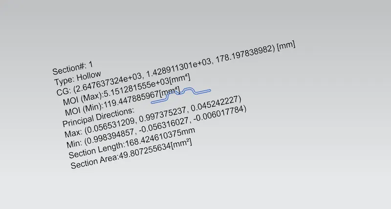
Moment Of Inertia
Centre Roof:
Bow Roof 1:
Bow roof 2
| Position | Iy | Lx | Ly | α | Y | My | t | Qr | Result |
| front roof bow front | 97.92 | 1137 | 2029.13 | .99 | 500.52 | 765099.87 | .75 | 1.41 | NG |
| bow front -center roof | 411.23 | 1082.3 | 2029.13 | .92 | 519.45 | 784203.276 | .75 | 3.94 | OK |
| center roof bow rear | 119.447 | 1056 | 2029.13 | .87 | 501.23 | 765829.317 | .75 | 3.22 | OK |
For the second and third condition the design is OK but we need to increase strength by adding embosses in the first condition
Conclusion
For improved support and strength, we were able to design the roof with all of the roof rails. By computing the heat distortion requirements and the snow load criteria, we created it in a way that complies with standards and laws. While doing this, we also gained an understanding of the technique used to design the car's roof and the factors we took into account.