Roof Design
AIM :
For the Given Roof styling, create an ASSEMBLY by developing the essential flanges for the outer roof and creating the reinforcements.
Provide appropriate dimensions and check for Draft analysis.
Do a curvature study on the roof and perform calculations to determine the position of the Bow-roofs.
Suggest and implement remedies in the design if the criterion is not full-filling
Start with the creation of a roof ditch area with a tool opening angle of 7 degrees.
Develop the reinforcements as separate parts
Different types of reinforcements that the car has are :
- Front roof rail
- Bow roofs
- Central roof rail and
- Rear roof rail
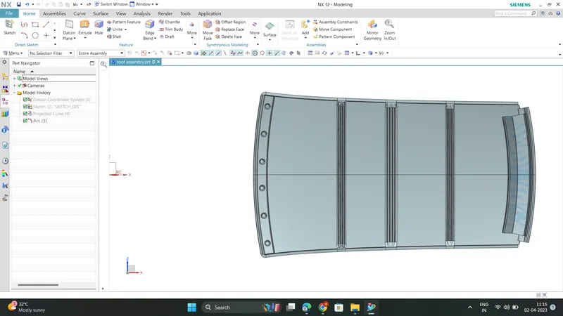
Front Roof Rail :
Front roof rail is the one which joins the wind shield glass , body side outer and the inner panel also. Here the front roof rail is designed based up on the master section given
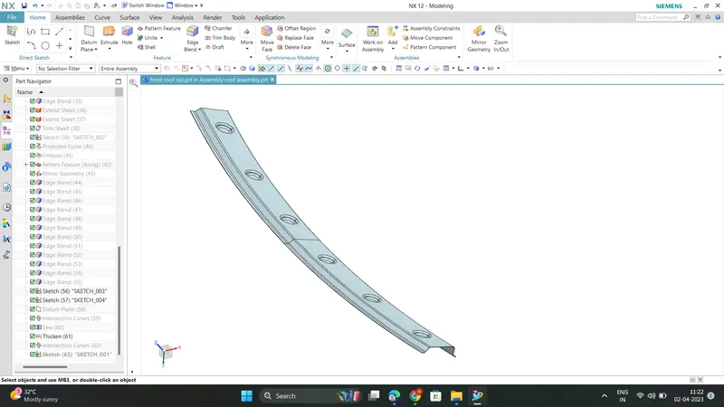
Rear Roof Rail :
Rear roof rail is the one which joins the back door and the body side outer
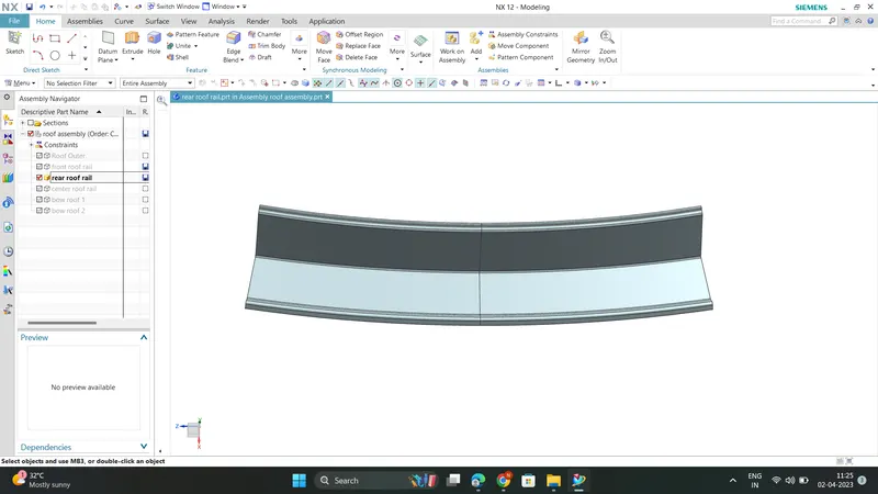
CENTRAL ROOF RAIL :
central roof rail helps in providing effectively support to the flat area of the roof as it is more susceptible to failure under the action of load . generally central roof rail is placed at the center of the roof which is connected to the B-pillar support structure . This central roof rail helps in adding the strength to the roof during the rool- over test. The thickness of the central roof rail is 1.25 mm .
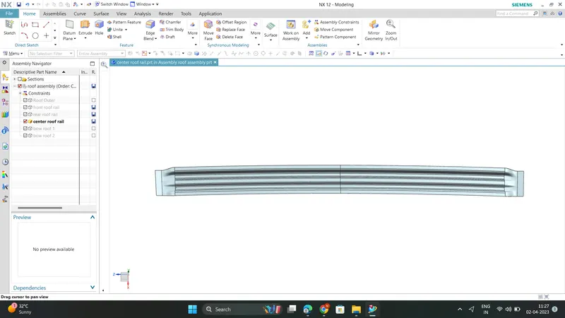
BOW ROOFS :
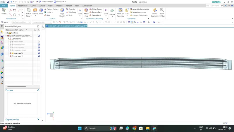
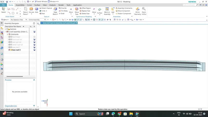
The bow roofs are give to improve the torsional stiffness and load bearing capacity of the roof structure . The number of bow roof present is depends on the overall size of the roof . Presently in this project two bow roofs are added.
Bow roof 1
Bow roof 2
Manufacturing process:
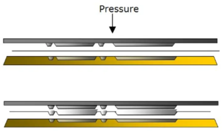
Embossing:
Embossing is the process of giving a 3-dimensional look to a material or product. Pressure is applied to the surface of the material and results in an image will project on the surface of the material. ‘Relief’ is another term used to encompass the process of embossing.
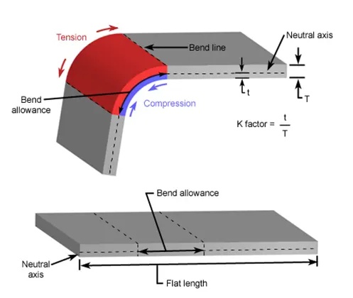
Bending:
It involves applying for to the sheet metal workpiece to produce a curvature. In generally bending are used to produce simple curvature surface instead of complex. Amount of pressure is important to change the sheet metal surface into the given shape.
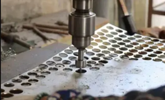
Drill:
Drilling a hole in sheet metal with a twist drill is a rather straightforward operation. You start off by drilling a small diameter pilot hole, and then drill gradually larger holes until you get to the size you need.
JOINING PROCESS :
Mastics are introduced between the roof outer panel and the reinforcements for joining . where ever the mastic are introduced there is remarkable improve of the strength
Spot welding is also introduced to join the reinforcements and the outer panel
DESIGN CONSIDERATIONS FOR A ROOF :
- Visibility criteria
- Head clearance
- Curvature study
- Heat distortion and snow load criteria
- Draft analysis
DRAFT ANALYSIS :
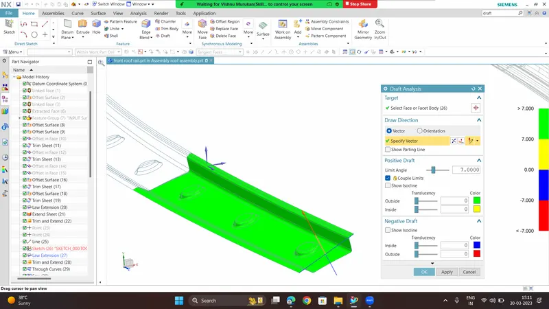
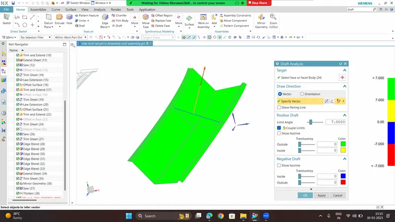
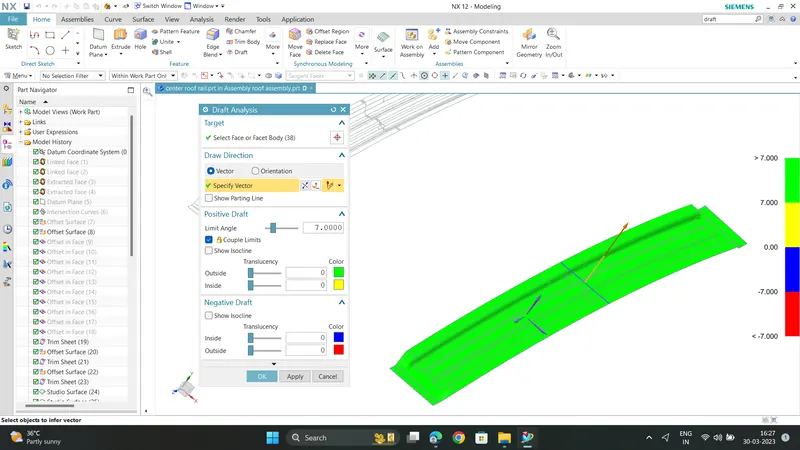
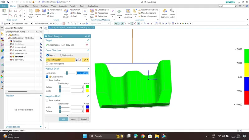
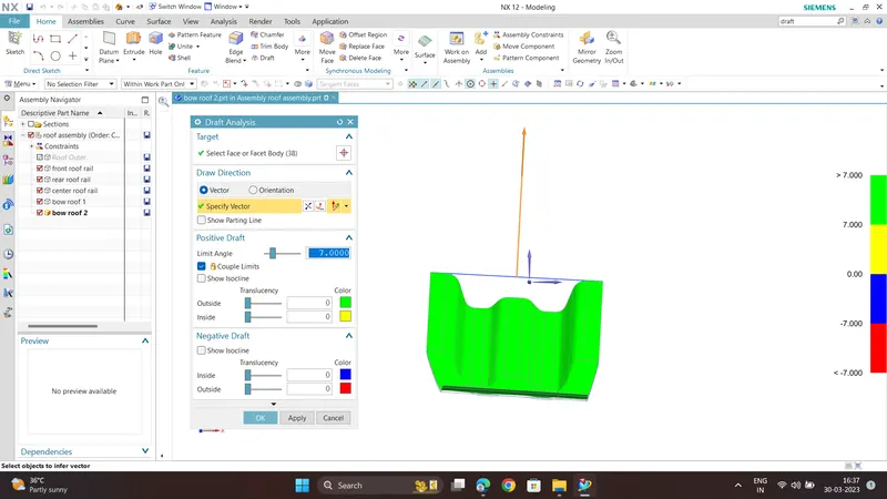
The Draft Analysis command enables you to detect if the part you drafted will be easily removed. This type of analysis is performed based on color ranges identifying zones on the analyzed element where the deviation from the draft direction at any point, corresponds to specified values.
Minimum draft angle is 7 degree is considered for analysis. Green colour show positive draft angle of the part more than 7 degree.
Front roof rail
Rear roof rail
Central roof rail
Bow roof 1
Bow roof 2
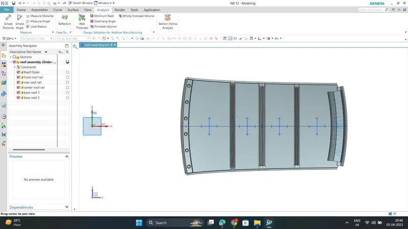
CURVATURE STUDY ON THE ROOF:
- Heat Distortion
- Snow Load
HEAT DISTORTION:
The heat distortion study the plays an important role in Sheetmetal application. Heat distortion is temperature limit above
which material cannot be used for structural application. This study is useful to fin the where the material starts to soften when
exposed to a fixed load at elevated temperature. In order to avoid the bending, damage to the roof based on the heat distortion
temperature. This study will provide the which position of the bow roof give enough strengthen to roof.
Bow–Roof Prediction Formula
W = [1.73 x 10^(-3) x L] + [1.85 x 10^(-8) x (R^2)/t] + [ 1.10x10^(-3) x l] - 2.68
Where,
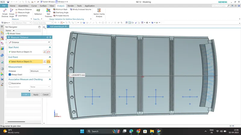
L = Roof Length in X-Direction[mm] (Roof dimension in 0-Y)
R = Roof curvature
R = 2(Rx*Ry)/(Rx+Ry)
Rx = X curvature
Ry = Y curvature
t = Roof plate thickness [mm]
l = Bow Roof Span [mm]
| Roof Rail | Rx (mm) | Ry(mm) | R(mm) | L(mm) | t(mm) | l(mm) | W | Result |
| FR-Bow1 | 5700.77 | 2949.22 | 3887.36 | 2038.99 | 0.75 | 522.5102 | 1.2 | PASS |
| Bow1-Central | 4828.24 | 6771.76 | 5637.192 | 2038.99 | 0.75 | 294.2516 | 1.9 | PASS |
| Central-Bow2 | 4039.69 | 10261.59 | 5797.199 | 2038.99 | 0.75 | 364.3426 | 2.07 | PASS |
| Bow2-RR | 3305.54 | 14415.05 | 5377.86 | 2038.99 | 0.75 | 398.0740 | 1.99 | PASS |
FINAL RESULTS OF HEAT DISTORTION :
W = [1.73 x 10^(-3) x L] + [1.85 x 10^(-8) x (R^2)/t] + [ 1.10x10^(-3) x l] - 2.68
From the above table it can be concluded that all values of w<2.7 So thus it infers that current positioning of bow rows are good in state as per design and found ok
Snow Load Prediction Formula :
Qr = [Iy x t2] / [α x s x [(Rx + Ry)/2]2 x 10-8].
Where,
α = My x Lx2 x 10-12 , My = Y(Ly-Y)
t = Roof plate thickness [mm]
Ly = Distance between the front and rear roof Rails on the Vehicle along with 0Y[mm]
Length of Roof panel with the center point between Roof rail Front /Rear as the front and rear reference point.
Lx = Distance between the Left and Right end of the roof on the Roof BOW [mm]
The width of the roof panel is exposed on the surface.
Y = Distance front Front Roof Rail to Roof BOW[mm]
s = Distance for which Roof BOW bears divided load [mm]
s = L1/2 + L2/2
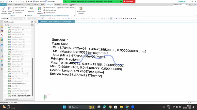
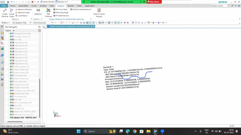
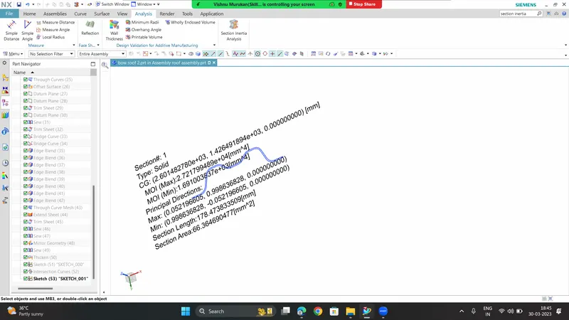
Iy = Geometrical moment of inertia of Roof BOW (Y cross-section )[mm4]
Rx = Lateral direction curvature radius of roof panel Y cross-section on Roof BOW [mm]
Roof panel curvature Radius of the Length Lx in Front view
Ry = Longitudinal Direction curvature radius of the Roof panel X cross-section on Roof BOW [mm]
Roof panel X curvature radius of length s in Side view
Judgment condition
Qr ≥ 3.1
MOMENT OF INERTIA:
Front Roof Rail

Bow roof 1
Central roof rail
Bow roof 2
| Roof Rails | Iy(mm) | Lx(mm) | Ly(mm) | L1(mm) | L2(mm) | Rx(mm) | Ry(mm) | t(mm) | y | s | My | α | Qr | Result |
| FR-BOW1 | 6.767*10^3 | 1114.7224 | 1921.0780 | 591.2176 | 375.5316 | 4304.853 | 2429.084 | 0.75 | 591.2176 | 483.37 | 786232.144 | 0.976 | 71 | PASS |
| BOW-CR | 1.677*10^3 | 1096.98 | 1921.0780 | 375.531 | 442.5011 | 5320.558 | 6720.859 | 0.75 | 966.7492 | 409.01 | 922588.98 | 1.146 | 5.55 | PASS |
| CR-BOW2 | 2.229*10^3 | 1074.867 | 1921.0780 | 442.5011 | 511.8276 | 4245.323 | 10709.419 | 0.75 | 1409.2504 | 477.16 | 721282.539 | 0.896 | 5.24 | PASS |
From the above table , it is observed that obtained values of QR > 3.1 .Hence the Snow Load Condition is satisfied .
CONCLUSION :
From the necessary Calculatons ,the roof , front roof rail, bow roof rails , central roof rail and the rear roof rail is designed by following
the master sections and all required conditions are satisfied for design and the moment of inertia and draft analysis are carried out to check feasibility manufacturing.