Roof Design
Objective: The objective of this project is to design car roof with essential flanges and reinforcements like ditch area, front roof rail, bow roofs, central roof rail and rear roof rail for the given styling surface Perform the calculations for the heat distortion and snow load criteria to determine whether the bow roofs…
Introduction:
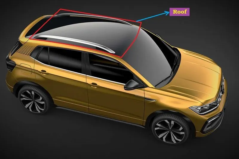
An automobile roof or car top is the portion of an automobile that sits above the passenger compartment, protecting the vehicle occupants from sun, wind, rain, and other external elements. Roof is the structure above the wind shield glass having the reinforcements to provide the strength to the overall structure.
Types of car roofs:
- Convertible roofs
- Hardtops.
- Sunroofs.
- T-tops.
- Targa tops.
- Vinyl roofs.
Roof Crush Test:
Therefore, passenger safety is also a very important parameter in front of OEMs. For this reason, strength is a very important criteria for designing a vehicle roof.
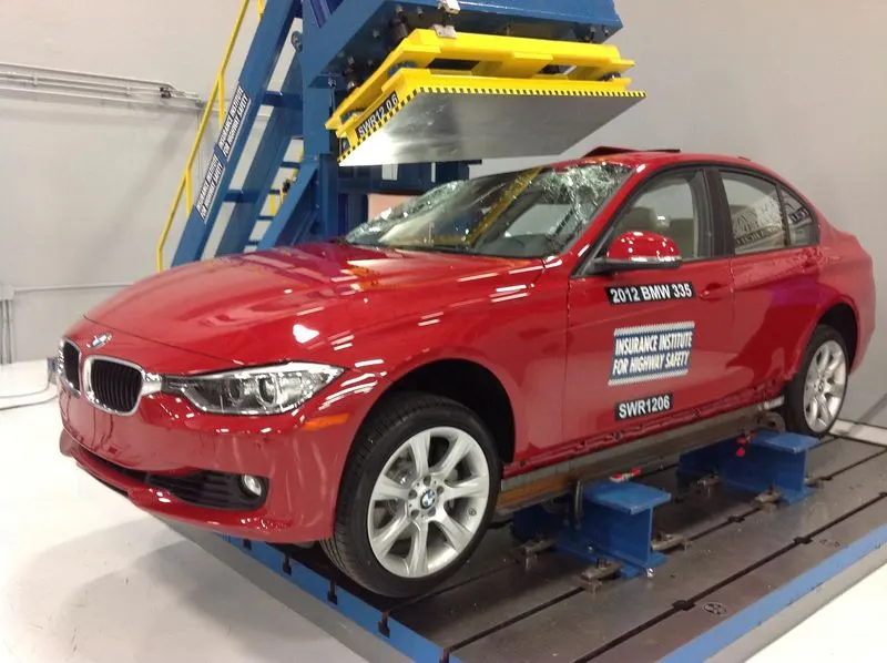
The strength of the roof structure to occupant the protection in real world crashes, requiring the maximum moving distance of the roof structure should be less than 127mm when the induced load is 1.5 times the vehicle weight.
For the test, the passenger car shall be rigidly placed or positioned on horizontal surface with the doors locked and the window closed.
This test can be conducted on either side of the roof structure, the front left or front right side but not on both sides in one single test and still meet the requirements of the test. The rigid plate shall not move faster than 0.5 inches/second and the force applied on the plate shall not exceed the lesser of 1.5 times the unloaded vehicle weight (UVW) expressed in kilograms multiplied by 9.8 or 5000lbs
Also, the direction of the forces shall be downward and perpendicular to the lower surface of the rigid plate and such that moves in a straight line without rotation. The duration of the test shall not exceed 120 seconds. The longitudinal axis of the plate is pitched forward at a 5° angle as viewed from the side of the passenger car.
Rollover accidents of a car are the most occurring accidents that we see in our daily lives. The passengers experience major injuries like neck, head and spine injuries. So, to reduce the injuries of a passenger from major fatalities it is important to provide safety in the car. Though safety is provided by seat belts and airbags during accidents, the passenger must have sufficient space for survival in the car during accidents. The roof of the car must have high strength to resist the crush force to avail the passenger some space for survival. Therefore, in this project, we have carried out roof crush test using Federal Motor Vehicle Safety Standards (FMVSS216) standards in LS dyna software. We have used Hyper mesh software to mesh the model and to apply boundary conditions to it. And the rigid plate is used to crush the car roof as specified by FMVSS216 standards. The rigid plate is oriented on the car roof as specified by Insurance institute of highway safety (IIHS). And an alternate material is used to the car roof structure to the baseline model to check the crashworthiness of new material. The outcome of test results of the new material's strength to weight ratio (SWR) was compared to baseline model and the new material is proposed for the roof (B-pillar) which is found to be more crashworthy.
Why reinforcements ?
If the roof is flat it is very weak and cannot able to with stand the forces like snow, so in order to increase the strength of the roof these reinforcements like front roof rail, central roof rail, rear roof rail and the bow roofs are introduced and joined to the flat surface of the roof with the different joining process.
Front roof rail:
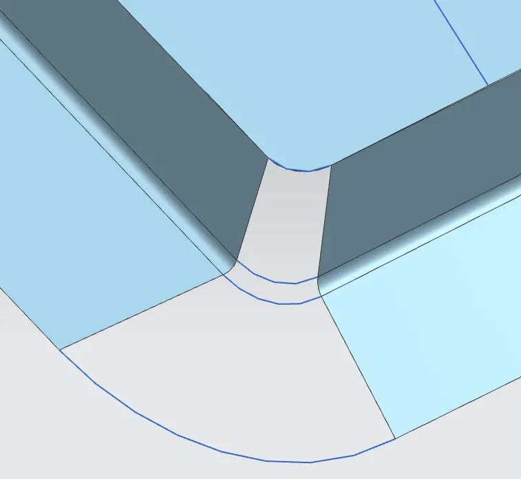
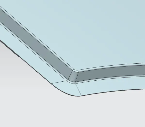
Front roof rail is the one which joins the wind shield glass, body side outer and the inner panel also.It is the support that is joined with the windshield glass, bodyside outer and the inner panels. The rails are furnished with embosses to improve the strength over length. It is usually made with thickness of 0.75 mm. a positive draft angle of more than 7 degree has been provided for deep drawing operation. The visibility criteria and the head room clearance of min 80 mm for the passenger are taken into consideration for the bottom most flange. Windshield end and the roof end are spot welded and joined and the other end of the front roof rail is joined with the roof using mastic sealant for increased strength. Front roof rail is designed with the help of given master section.
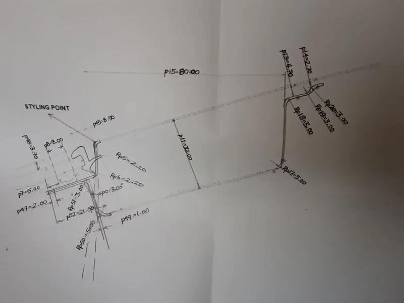
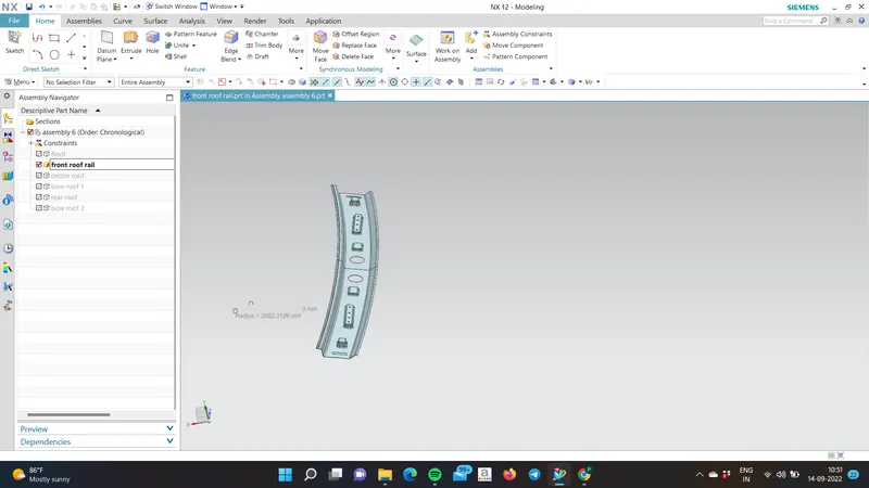
The Flanges are created at the front outer panel to avoid sharp edges by using bridge curve and Through curves.
Bow Roofs:
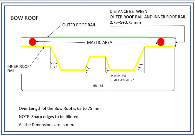
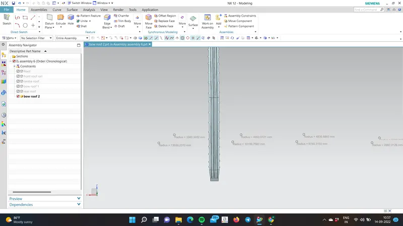
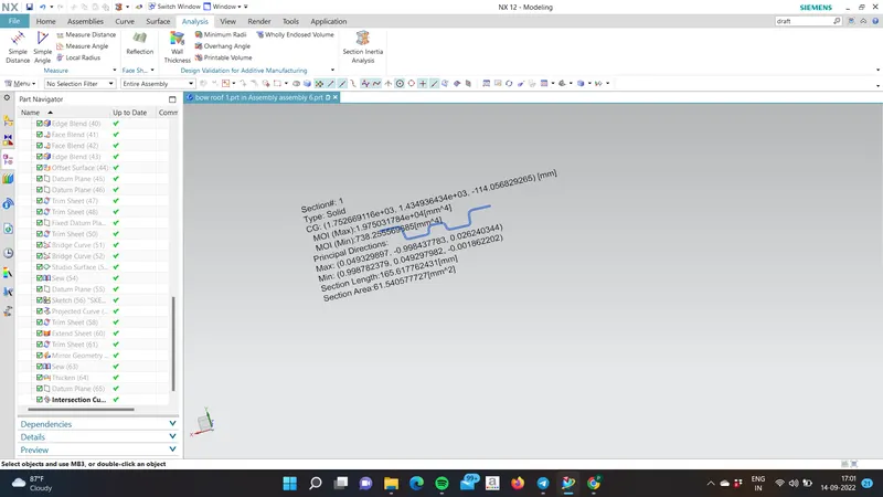
The bow roofs are given to improve the torsional stiffness and load bearing capacity of the roof structure. The number of bow roofs provided will depend upon the overall dimensions of the roof. Longer the roof more the bow roofs are integrated to BIW frame they are attached to the outer panel using mastic sealants. Each mastic point will have up to 80mm circular effective area. Special notches on the flanges are provided for the application of mastic sealant. Both Bow roof 1 and Bow roof 2 are similar in dimension and pattern only curvature profile is different at respective position. The positioning of bow roofs is done based on curvature study. The heat distortion criteria and snow load criteria are checked to analyse the position of the bows in various conditions.Bow roof rails is designed based up on the master section given.
Bow roof 1:
BOW ROOF RAIL 2
CENTER BOW ROOF:
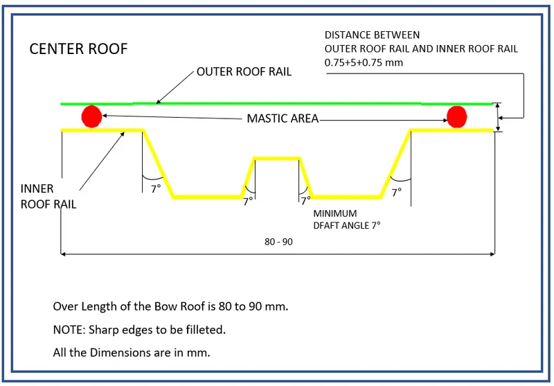
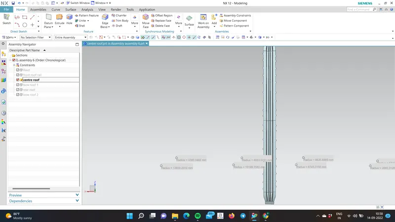
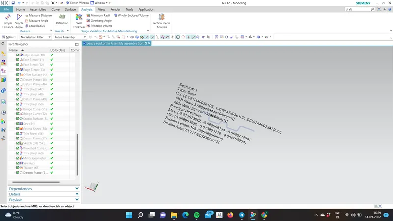
Centre roof rail is provided to effectively support the flat area of the roof as it is more susceptible to failure under the action of the load. usually, the center reinforcement roof rail will be placed at the center of the roof connecting the B pillar support structure which result in added support in the roll over test.Centre roof rails is designed based up on the master section given.
REAR ROOF RAIL:
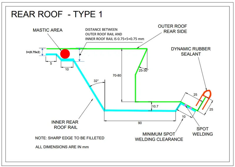
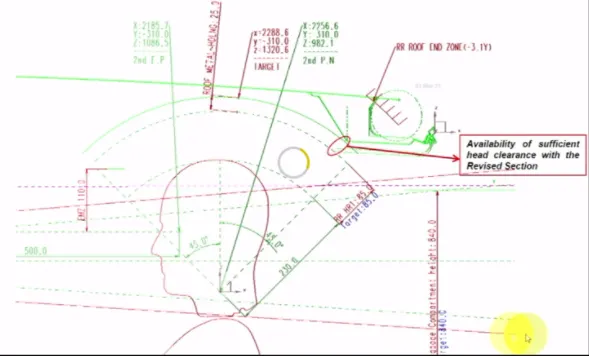
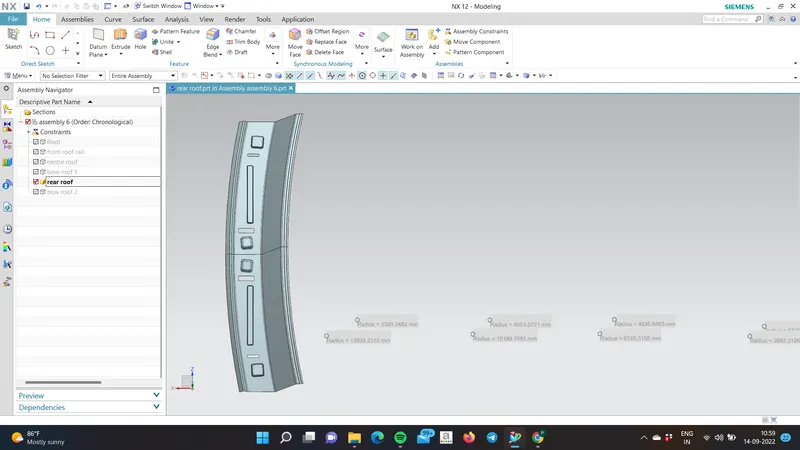
It is the support which is joined to the back door and the body side outer and the inner panels. It is also usually made from body side outer scrap and therefore thickness of the rail is 0.75 mm. similar to the front roof design, we have to take into consideration the rear headroom clearance and the rear visibility criteria while designing the rear roof rail. Spot welds are applied at the backdoor end of the rail and the other end is joined with the roof using mastic sealants.While designing the rear roof rail we need to take care of the head clearance of the passenger & the Rear Visibility Criteria.Rear roof rail is designed based up on the master section given.
Assembled Images:
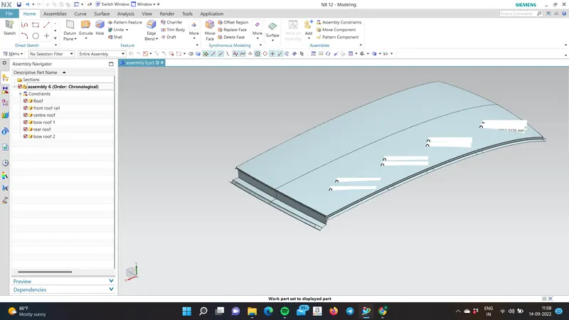
positioning of the Rails:
- Heat Distortion Curvature Study:
The heat distortion study plays an important role in sheet metal usage. Heat distortion temperature is a temperature limit above which material cannot be used for the structural applications. This study is used to predict the heat distortion temperature at where the material starts to soften when exposed to a fixed load at elevated temperature. In order to avoid bending or damages on the roof, based on the heat distortion temperature, this study will predict the bow roof position temperature, this study will predict the bow roof position which help to strengthen the roof.
Bow–roof prediction Formula
W = [1.73 x 10^(-3) x L] + [1.85 x 10^(-8) x (R^2)/t] + [ 1.10x10^(-3) x l] - 2.68
Judgement Condition: OK< 2.7> 3.1
Where,
L = Roof Length in X-Direction[mm] (Roof dimension in 0-Y)
R = Roof curvature
R = 2(Rx*Ry)/(Rx+Ry)
Rx = X curvature
Ry = Y curvature
t = Roof plate thickness [mm]
l = Bow Roof Span [mm]
steps followed:
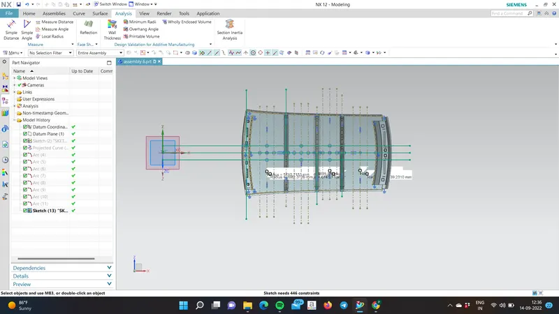
- From O-Y axis, at -3y about distance 300mm is drawn parallel on the perpendicular plane as shown in fig. after that 100 mm lines are offset to either side of -3Y line. Now center lines are drawn between each adjacent roof rail edges respectively. Intersection points are marked on the sketch and exit the sketch. Make all geometry in construction lines except the points.
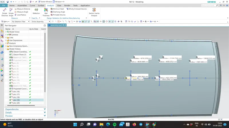
- Project the intersection points in the sketch to roof surface as shown in fig.
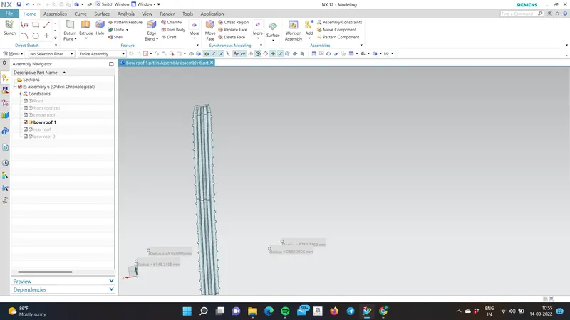
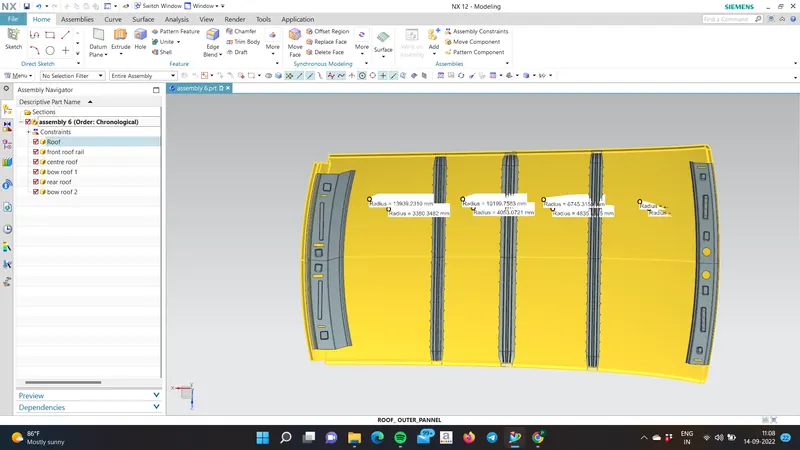
- Join the projected curves using arc curve and measure the minimum radius and linear dimension as follow and put into the formula to calculate W.
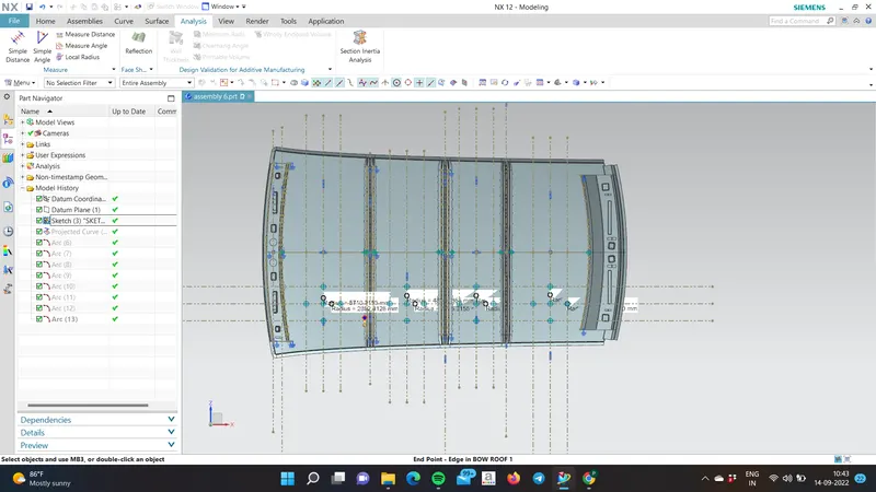
fig. showing -nY axis and intersection points
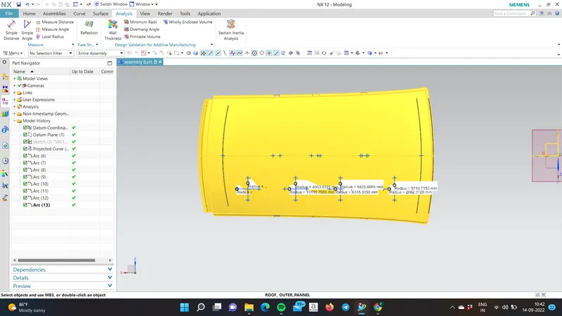
fig. projecting poits on roof for Rx & Ry
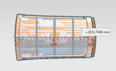
fig. L distance of styling surface
|
Roof Rail Span From |
L (mm) |
Rx (mm) |
Ry (mm) |
R |
t (mm) |
l (mm) |
W |
Result |
|
FR- Bow1 |
2033.7048 |
5710.7153 |
2882.3126 |
3831.0283 |
0.75 |
534.02 |
1.6984 |
OK |
|
Bow1-Bow2 |
2033.7048 |
4835.8865 |
6745.3155 |
5633.1942 |
0.75 |
464.45 |
2.1103 |
OK |
|
Bow2-Bow3 |
2033.7048 |
4053.0721 |
10199.7583 |
5801.0029 |
0.75 |
464.73 |
2.15 |
OK |
|
Bow3-RR |
2033.7048 |
3380.3482 |
13939.2310 |
5441.1777 |
0.75 |
464.93 |
2.02 |
OK |
Here
- 'l' value is from one reinforcement centre to other reinforcement centre value.
- 'L' value is total length from one end to another end.
According to the judgement criteria OK< 2.7> 3.1, All values are satisfied.So as per my design the roof will pass the HEAT DISTORTION CRITERIA.
Snow Load Calculation:
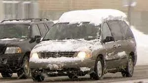
In the winter season, in some countries there will be a huge load of snow on the roof top of the car. Snow load criteria study is done to check the ability of the roof to withstand snowfall and bounce back to its original shape without a permanent deformation once the load is removed.
Snow load Prediction formula
Qr = [Iy x t2] / [α x s x [(Rx + Ry)/2]2 x 10-8]
Note: The Qr value given over here is correct. There was a type error in the formula given in the video.
Where
α = My x Lx2 x 10-12 , My = Y(Ly-Y)
Judgement condition = Qr ≥ 3.1
250 ≤ s ≤ 380
t = Roof plate thickness [mm]
Ly = Distance between the front and rear roof Rails on the Vehicle along with 0Y[mm]
Length of Roof panel with the center point between Roof rail Front /Rear as the front and rear reference point.
Lx = Distance between the Left and Right end of the roof on the Roof BOW [mm] Width of the roof panel exposed on the surface.
Y = Distance from Front Roof Rail to Roof BOW [mm]
s = Distance for which Roof BOW bears divided load [mm]
s = L1/2 + L2/2
Iy = Geometrical moment of inertia of Roof BOW (Y cross-section) [mm4]
Rx = Lateral direction curvature radius of roof panel Y cross-section on Roof BOW [mm] Roof panel curvature Radius of the Length Lx in Front view
Ry = Longitudinal Direction curvature radius of the Roof panel X cross-section on Roof BOW [mm] Roof panel X curvature radius of length s in Side view
Steps Followed:
- At O-Y axis on perpendicular plane to roof as shown in fig, draw 100 mm lines offset to either side of OY axis line. Now center lines are drawn between each adjacent roof rail edges respectively. Intersection points are marked on the sketch and exit the sketch. Make all geometry in construction lines except the points.
- Project the intersection points in the sketch to roof surface as shown in fig.
- Join the projected curves using arc curves and measure the minimum radius and linear dimension.
- Project the intersection plane bow roof and center roof rail on the horizontal plane to find the moment of inertia of the respective section to find ly values.
- Put all the linear and radial dimension in following formula to calculate Qr value.
 \
\
Section modulus study of the Roof Rails:
The section modulus of the cross-sectional shape is of significant importance in designing of structures. It is a direct measure of the strength of the structure
A structure that has a larger section modulus than another will be stronger and capable of supporting greater loads.
Section modulus (S) = I/y
Where,
I = Moment of inertia in (mm4)
y = Distance between the neutral axis and the extreme end of the object (mm)
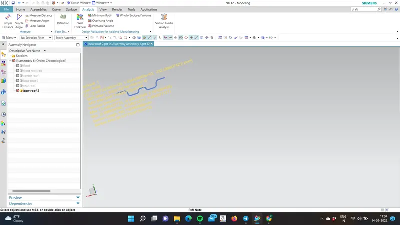
Bow Roof Rail 1:
Bow Roof Rail 2:
Bow Roof Rail 3:
|
Roof Rail Span From |
Iy (mm^4) |
L1 (mm) |
L2 (mm) |
Lx (mm) |
Ly (mm) |
Rx (mm) |
Ry (mm) |
t (mm) |
y (mm) |
s |
a |
Qr |
RESULT |
|
FR- Bow1 |
951.707 |
1468.4598 |
499.3084 |
1140.9571 |
2032.0905 |
4625.0904 |
2481.3984 |
0.75 |
1462.4598 |
983.8742 |
1.08 |
3.3 |
OK |
|
Bow1-Bow2 |
738.25 |
499.3084 |
499.3304 |
1083.7781 |
2032.0905 |
3794.6378 |
6497.3651 |
0.75 |
499.3084 |
499.3194 |
0.89 |
6.33 |
0K |
|
Bow2-Bow3 |
658.237 |
499.3304 |
1479.7092 |
1057.2984 |
2032.0905 |
4297.2586 |
11402.4808 |
0.75 |
499.3304 |
989.5918 |
0.85 |
0.006 |
FAIL |
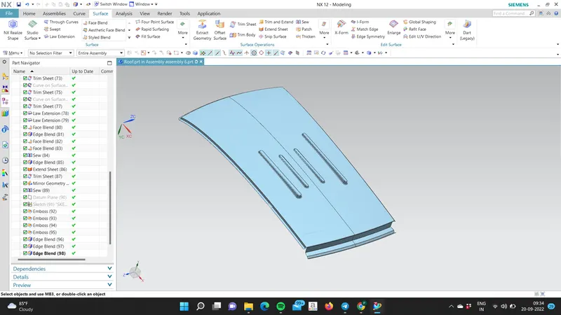
It is observed that the roof is satisfying the condition that are given. One last condition is not satisfying then creating the emboses in outer panel because the increasing the strength of the outer panel.
Draft Analysis:
Draft analysis was performed with 7 degrees value.
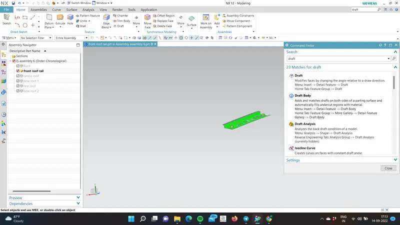
A.Front Roof Rail
- All the faces of Front Roof Rail have successfully cleared the draft analysis with a minimum draft angle of 7 degrees.
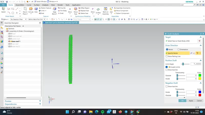
B.Bow Roof 1
- All the faces of Bow Roof have successfully cleared the draft analysis with the minimum draft angle of 7 degrees.
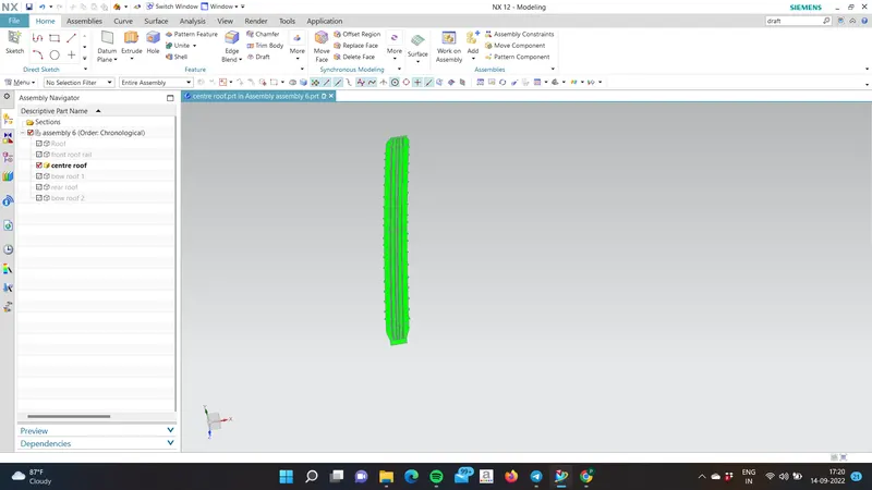
C.Centre Roof Rail
- All the faces of Centre Roof Rail have successfully cleared the draft analysis with a minimum draft angle of 7 degrees.
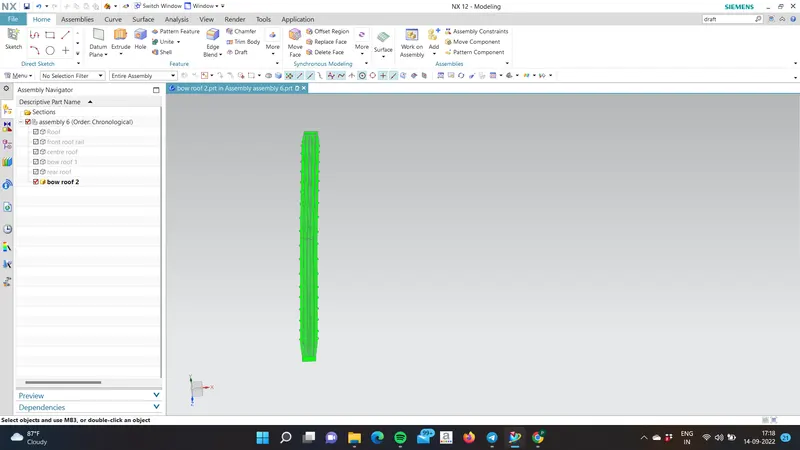
D.B0W ROOF 2
- All the faces of Bow Roof 2 have successfully cleared the draft analysis with a minimum draft angle of 7 degrees.
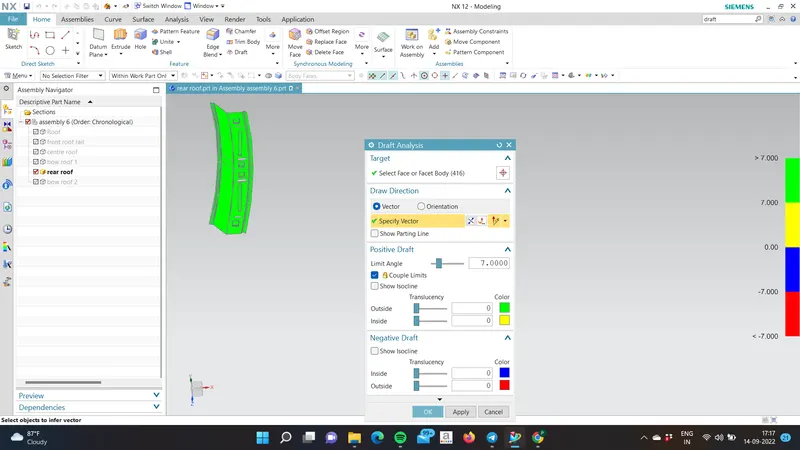
D. Rear Roof Rail
- All the faces of Bow Roof Rail have successfully cleared the draft analysis with a minimum draft angle of 7 degrees.
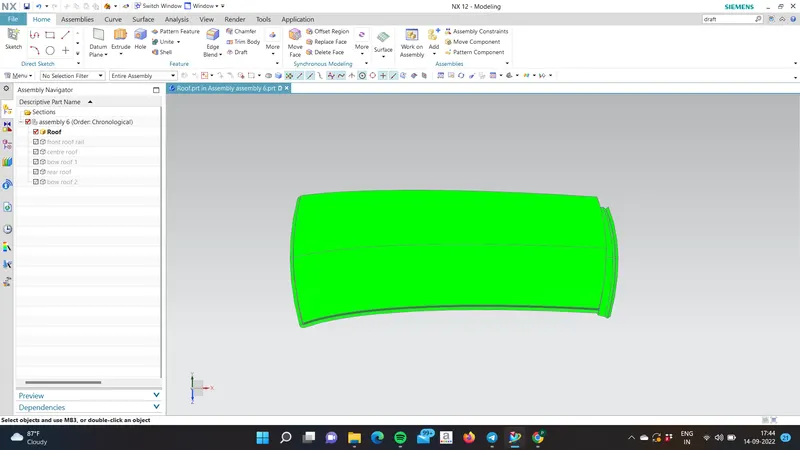
Outer Panel:
RESULTS :-
- All the parts have successfully cleared the draft analysis.
- The proposed Roof design has successfully cleared the heat distortion analysis.
- The portion between center roof and Rear Roof Rail is failing in Snowload analysis.
- Embosses have been provided onto the roof outer panel portion where it is failing in snowload analysis. Embosses increase the strength of the roof panel.
CONCLUSION :-
The roof has been successfully designed considering all the design Rules, Master sections, Manufacturing feasibility, Draft analysis, Heat distortion criteria, and snowload analysis.