Roof Design
Objective: 1. For the given Roof styling and master section, devlop the essential flanges and reinforcements, provide appropriate dimensions and check for Draft Analysis and also submit section inertia analysis report on O-Y section.
- Creating of Roof ditch area the Tool opening is only 3 to 5 degree.
- Design and Devlop Roof Rails as Per the given master Section.
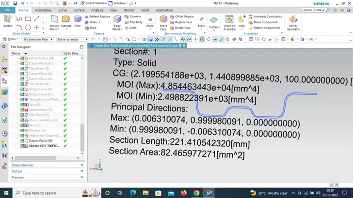
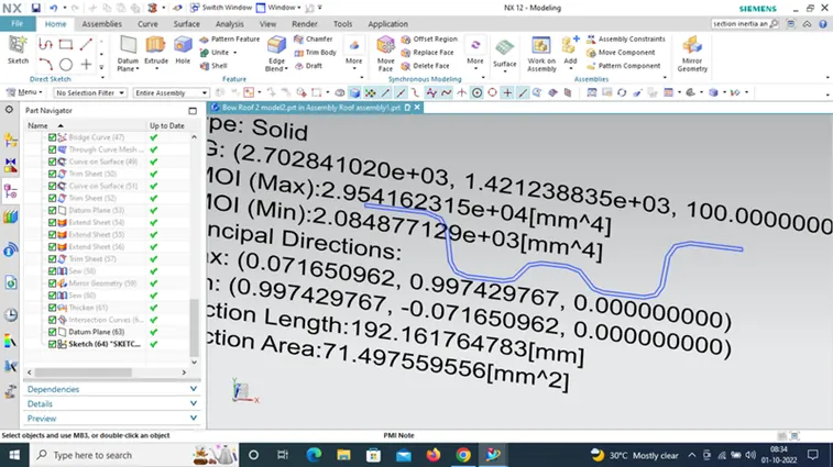
- Perform Section Modulus Study for the Front Roof Rail, Bow Roof Rail-1, Center Roof Rail, Bow Roof Rail-2 and Rear Roof Rail.
- To do a Curvature study on the Roof and Perform Calculations to determine the Position of the Bow Roofs.
- To Perform Heat Distortion Criteria and Snow Load Criteria tests on the Designed Roof and Do optimization if necessary.
Components of Roof:
- Roof Outer Panel
- Front Roof Rail
- Bow Roof Rail
- Center Roof Rail
- Rear Roof Rail
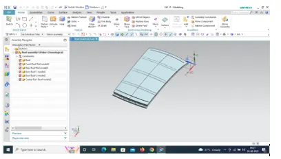
- Roof Outer Panel :
The Outer panel is the Class-A surface of the Roof which enclose the Top of the passenger compartment. It is designed to match the input styling Surface. Thus getting better aerodynamic performance as intended. It is also has intended significant role in the aesthetic of the vehicle.
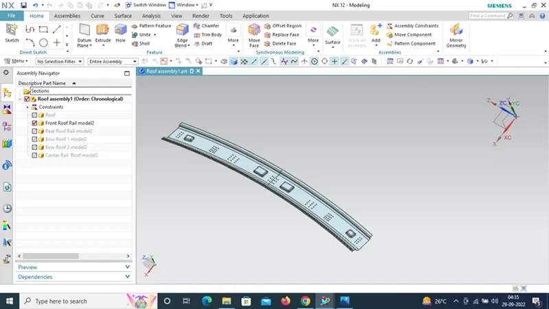
- Front Roof Rail:
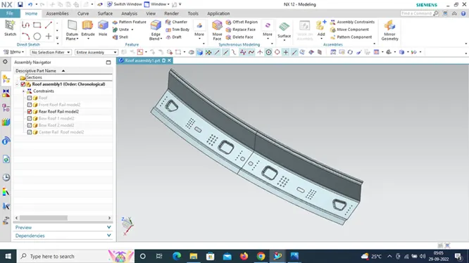
Front Roof Rail is designed according to given master Section. Further Darts and Embosses are Furnished on Same Portion of the front Roof Rail to increase the Strength of the Rail. A gap of 5mm is provided between the Roof Surface and the Rail Roof Side flange . Thickness of 0.75mm is maintained.
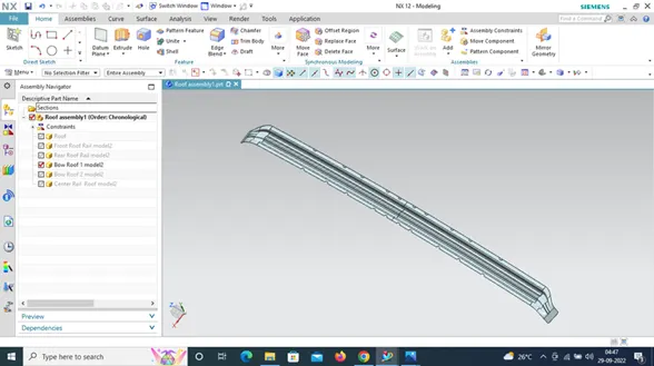
- Bow Roof-1 & Bow Roof-2
Bow Roofs provide strength to the Roof for Load Carrying. The Cross -section of the Bow Roof is W so as to Provide more Strength to the Roof. Embossing is done on the surface to provided the local strength to the Bow Roofs. The Rear side of the rail is Spot welded with the Ditch area of the Roof and the other side is attached using mastic sealant.
Thickness of 0.75 is given for Both Bow Roofs.
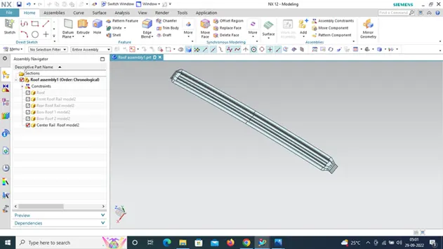
- Center Roof Rail:
Similar to other Rail Design we have to take into consideration Headroom clearance and the visibility criteria while designing the center Rail and Bow Rail. But Unlike the Front and Rear Rails, Spot welds are not applied for joining these rails to the roof. Instead, Mastic Sealant are introduced at both ends since center Roof Rail are Positioned under Styling Surface of the Roof.
For incresing the strength of the Rails, Embossing is done. To reduce Weight of the material used, a different styling has been followed with the Thickness of 0.75mm.
- Rear Roof Rail:
It provides the Strength to the Rear Part of the Roof so that the Back Door can be Mounted. Bead and Embossing are done on the surface to provided Local Strength to the Rear Rail. Thickness Of 0.75 is maintained.
Roof Specifications :
The delivery tests specified the Roof assembly are static, dynamic and impact. The Purpose of static testing is to verify that Roof assembly exhibits no permanent deflection due to distributed load representing snow load and due to Heat Distortion.
Bow- Roof prediction Formula:
W=[1.73*10^(-3)*L]+[1.85*10^(-8)*(R^2)/t]+[1.10*10^(-3)*l]-2.68
Judgment Condition: OK<2.7
Where
L= Roof Length in X-Direction [mm] (Roof dimension in 0-Y)
R= Roof Curvature
R= 2(Rx*Ry)/(Rx+Ry)
Rx= X curvature
Ry= Y curvature
t =Roof plate thickness [mm]
l = Bow Roof Span [mm]
Procedure to measure Rx & Ry:
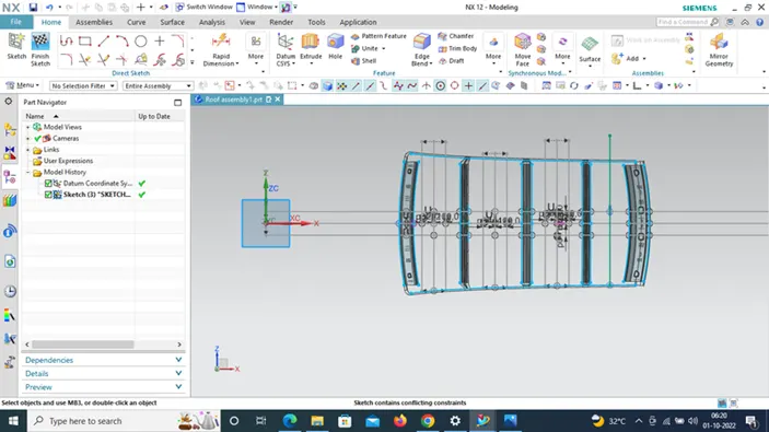
- Consider a plane above the roof at the some distance & enter the sketch workbench.
- Draw a line at -3Y at -300mm from O-Y axisis and Offset it to 100mm on Both Side of -3Y lines.
- Draw Vertical lines between every two adjacent roof rails. Make these lines as reference line.
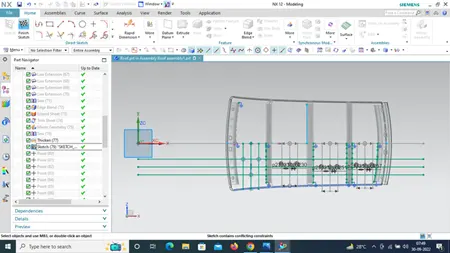
- Create Points at the intersection of the lines as Shown. Then project these points on the Roof Surface and Using 3 Point Arc to draw to measure the Radius.
Now, We have Rx & Ry.
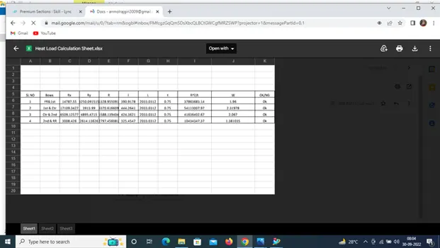
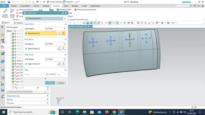
Finally, collecting all the required Data by measuring Subtitute equation. if W<2.7 then We can Go ahead Position Of Bow Roof Rails.
Snow Load Calculation:
Qr = [Iy x t2] / [α x s x [(Rx + Ry)/2]2 x 10-8]
Note: The Qr value given over here is correct. There was a typo error in the formula given in the video.
Where,
α = My x Lx2 x 10-12 , My = Y(Ly-Y)
t = Roof plate thickness [mm]
Ly = Distance between the front and rear roof Rails on the Vehicle along with 0Y[mm]
Length of Roof panel with the center point between Roof rail Front /Rear as the front and rear reference point.
Lx = Distance between the Left and Right end of the roof on the Roof BOW [mm]
The width of the roof panel is exposed on the surface.
Y = Distance front Front Roof Rail to Roof BOW[mm]
s = Distance for which Roof BOW bears divided load [mm]
s = L1/2 + L2/2
Iy = Geometrical moment of inertia of Roof BOW (Y cross-section )[mm4]
Rx = Lateral direction curvature radius of roof panel Y cross-section on Roof BOW [mm]
Roof panel curvature Radius of the Length Lx in Front view
Ry = Longitudinal Direction curvature radius of the Roof panel X cross-section on Roof BOW [mm]
Roof panel X curvature radius of length s in Side view
Judgment condition
Qr ≥ 3.1
250 ≤ s ≤ 380
Procedure to measure Rx & Ry:
- Consider a Plane above the Roof at some distance & enter the sketch Workbench.
- Draw a line at OY and offset it to 100mm on both side of 0-y line.
- Draw Vertical lines between every two adjacent roof rails. Make these line as reference line.
Calculatio Of Moment Of Inertia Of 3 Section Respectively -:
Draft Analysis-:
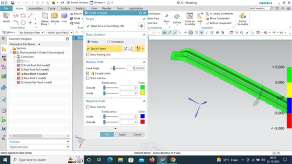
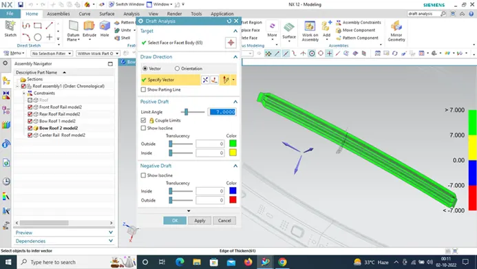
No Component can be ejected at 90 degree angle there should be some draft given for Easy removal after performing the respective operations to form a sheetmetal component. The minimum draft angle of 7 degree should be provided for the Sheetmetal components so that there shall be no deformation in the component after it is removed from the punching or any other operation.
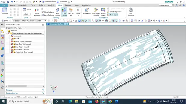
Draft Analysis is performed on each and every sheetmetal component with minimum 7 degree draft angle and result are satisfied.
Bow Roof 1:-
. Bow Roof 2 :-
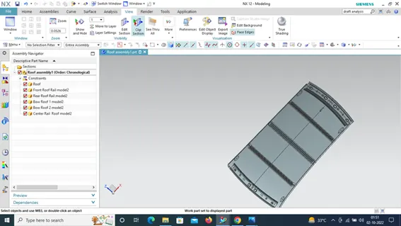
Final Model Of Car Roof With Roof Rails.
Conclusion:
. As per design guidelines Outer Roof, Front Roof Rail, Bow roof-1, Center rail Roof, Bow roof-2 and Rear Roof Rail are designed.
. The design fulfil the Heat absorption Criteria and Snow Load Criteria.
. Draft analysis performed to check tooling Feasibility .