Roof Design
Aim:
To design & develop the Roof of a car with its components by following the master section and design parameters.
Objective:
- To develop the essential flanges and reinforcements using roof styling as input.
- To do a curvature study on the roof and perform calculations to determine the position of the Bow-roof.
- To determine the Heat Distortion Criteria of the car's roof.
- To find the section modulus on the O-Y section of the roof and also for all its components of it.
- To determine the Snow Load Criteria for a car's roof.
- To perform Draft Analysis on the final CAD model of the roof.
Introduction:
Car's Roof:
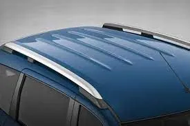
An automobile roof or car is the top portion of an automobile that sits above the passenger compartment, protecting the vehicle occupants from sun, wind, rain, and other external elements.
Methodology for designing the parts of the Roof:
1. Select the type of roof from the above list for the given skin data of the roof surface.
2. Deciding the number of bows to support the roof surface according to conditions.
3. Select the joining method used to join the roof surface with the front roof rail. rear roof rail, central roof rail, and bows.
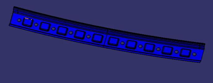
3. Designing the front roof rail and rear roof rail according to the given master sketch.
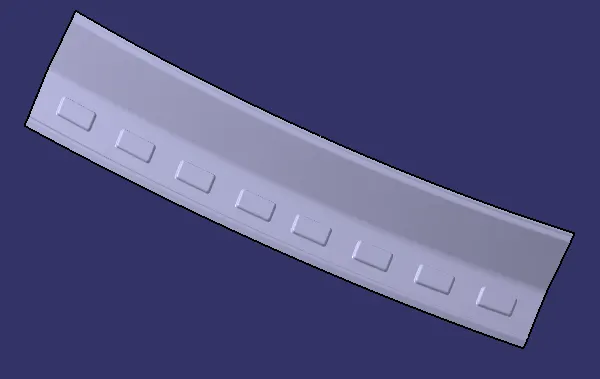
4. Designing the central roof rail and bows(as required) according to the given master sketch.
5. Calculating the parameters required for heat distortion criteria and checking the values of distortion in the roof is within range or not.
6. If the value of distortion in the roof body is not within the range, we need to change the position of the bows and central rail roof so that the distortion in the roof should be within range.
7. Next we have to do an iteration for the snow load condition to check the strength of the roof again if the value from the snow load condition is not in the range we have to do modifications in the bows section area and their position on the roof body.
Design Consideration and criteria:
1. Roof:
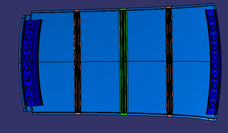
a.We are making the hardtop type of roof from the given master section so we are not adding any reinforcement for the central roof rail.
b.We are adding the flanges to all sides of the roof for spot welding of the front roof rail, central roof rail, rear roof rail, and bows.
c.The length and angle of the flange are decided based on the visibility criteria and according to the draw angle required for manufacturing the sheet metal.
d.The thickness of the roof is decided at 0.75mm
2. Front roof rail:
3. Rear roof rail:
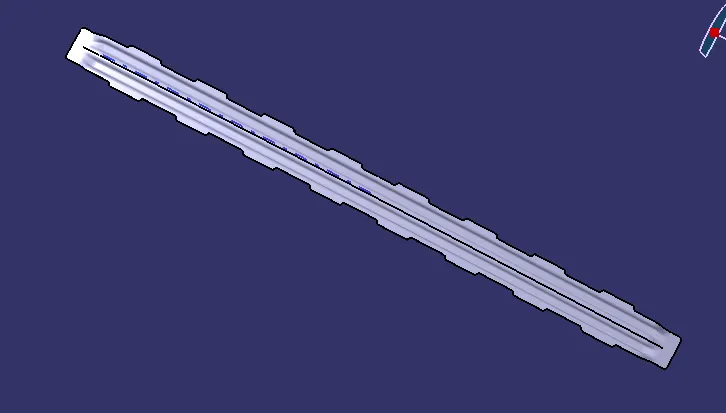
4. Bows:
5. Heat distortion criteria:
In this criterion, we check the heat distortion capacity of the roof at higher temperatures with the fixed load on it. So when the surrounding temperature is high and the roof is loaded with some weight on it then if the roof is deformed it fails, so to calculate whether the roof deforms or not, according to the position of the bow we do these calculations as follows
The formula for the heat distortion criteria:
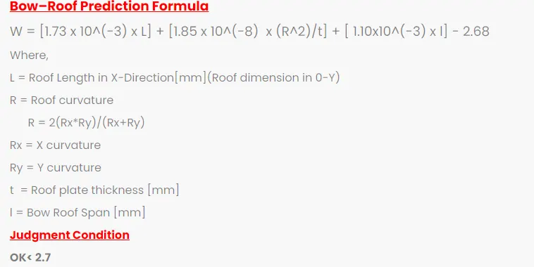
Steps to calculate the Heat distortions are as follows:
1. First we offset the center y-axis line to 300mm distance apart from it represented as (-3Y to 3Y red line).
2. After that we offset this -3Y to 3Y to 100mm offset each side represented with the green line.
3. We draw the vertical red line at the center of the two consecutive bow rood span. Next, we offset this red line to 100 on each side.
4. Now we have three horizontal lines and three 12 vertical lines we take the intersection points of the vertical red line with three horizontal lines and a horizontal red line we take the intersection of the vertical lines with that line.
5. After getting all the points we project these points on the roof surface and draw the three points curve along the x-axis point to get the radius of curvature of Ry and along the y-axis points to get the radius of curvature of Rx.
Heat distortion criteria:

Snow load Prediction:
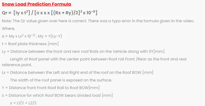
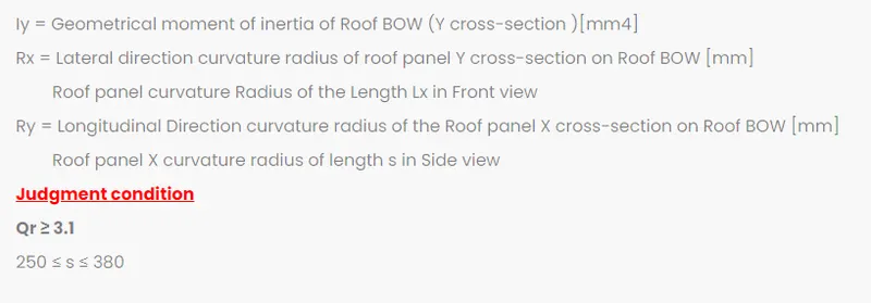
This evaluation was performed in a cold region where snow occurs. Roof design must pass through these calculations to ensure that it has sufficient stiffness to withstand the load due to the accumulation of snow over the roof.
Snow load Prediction Formula:

Section modulus calculation:
Section modulus is a geometric property for a given cross-section used in the design of beams or flexural members. Other geometric properties used in the design include an area for tension and shear, the radius of gyration for compression, and the moment of inertia and polar moment of inertia for stiffness. Any relationship between these properties is highly dependent on the shape in question.
Formula to calculate section modulus:
S=I/Y
where,
S - Section modulus
Y - Moment of inertia
I - Maximum distance between the neutral axis and one of the extreme ends of the object
Central Roof Rail & Bow roof :
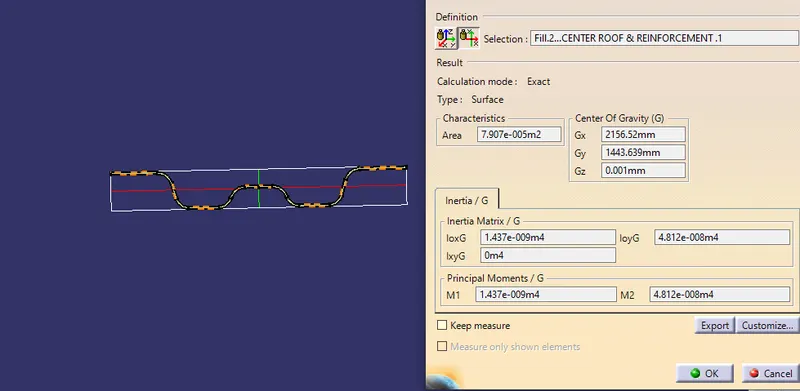
I = 1437
Y = 43.776
S = 32.83
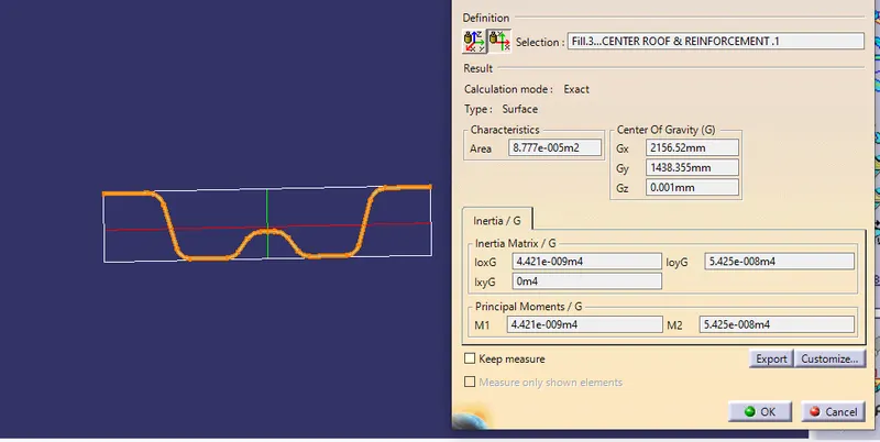
I = 4421
Y = 43.776
S = 101.0
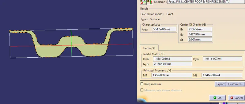
I = 1450
Y = 43.776
S = 33.18
Bow Roof :
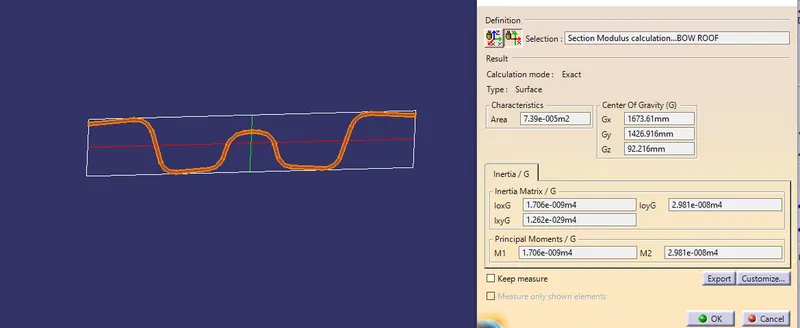
I = 1707
Y = 36.45
S = 46.83
Bow Roof 2:
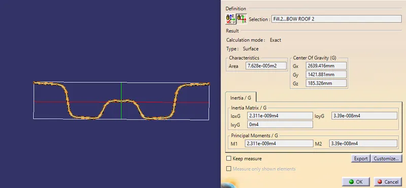
I = 2311
Y = 37.25
S = 62.04
Front roof rail:
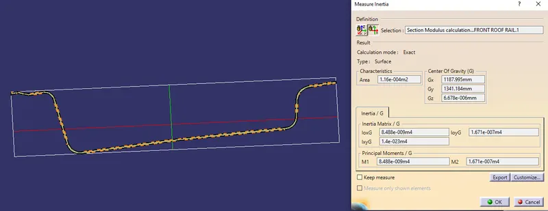
I = 8488
Y = 62045
S = 135.91
Rear roof rail:
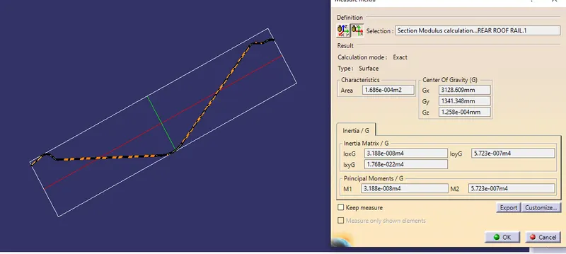
I = 3188
Y = 100.50
S = 31.72
Draft Analysis:
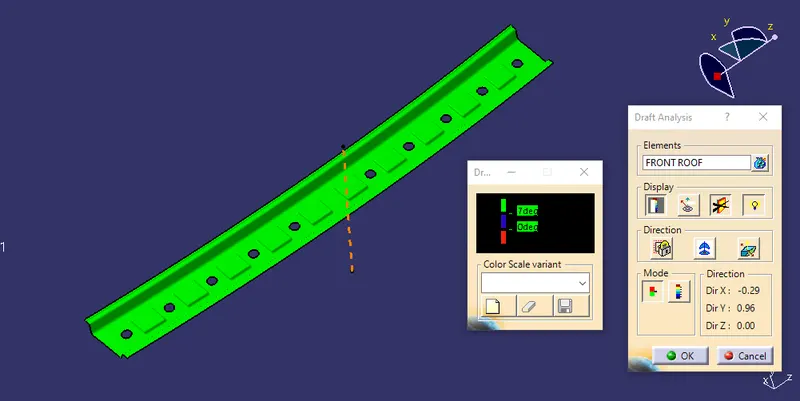
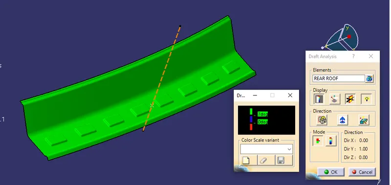
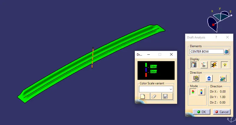
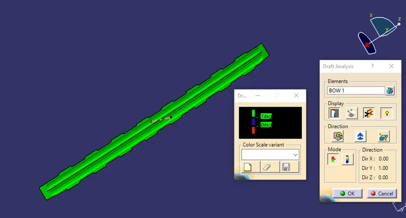
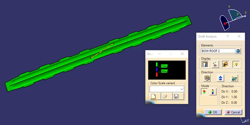
Parts cannot be ejected from the tool if it is at 90- degrees for this reason, a small draft is to be provided for each surface for the components in order to easily remove the components from the mold without any defects. The draft is the angle at which the part is tapered to allow it to release. Most sheet metal parts require a minimum of 7 degrees to 10 degrees however 7 degrees is widely accepted in sheet metal components design.
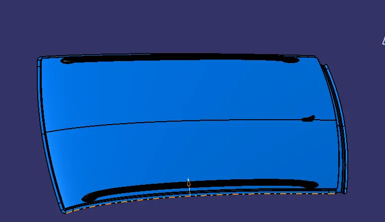
ROOF
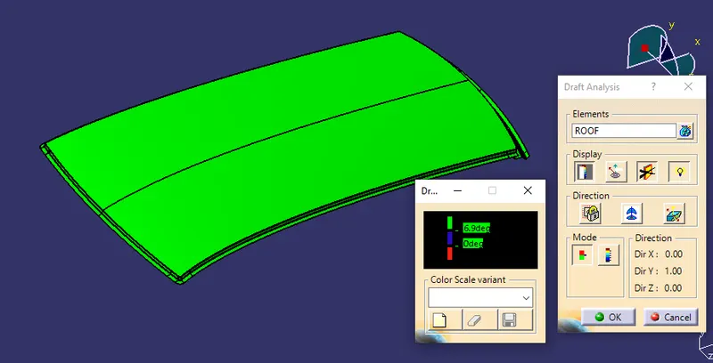
FRONT ROOF RAIL
REAR ROOF RAIL
CENTER ROOF RAIL
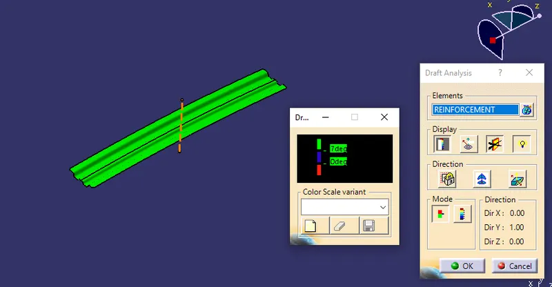
BOW ROOF 1 & 2
Joining Method used for manufacturing of Roof:
1. Spot welding points:
2. Mastic Points:
Assembled view
CENTER ROOF RAIL
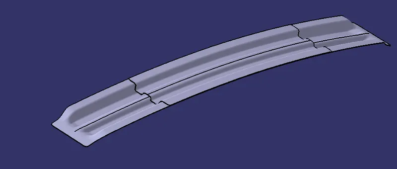
FRONT ROOF RAIL
REAR ROOF RAIL
BOW ROOF 1 & 2
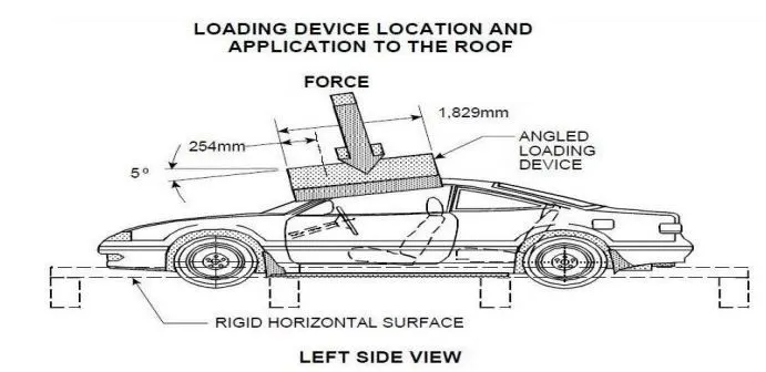
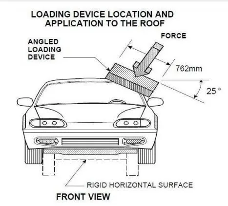
Actual test conducted by the National Highway Traffic Safety Administration(NHTSA) for rollover of the vehicle to check the roof strength :
RESULT:
The car Roof was designed by considering all the design parameters and the curvature study to resist Heat distortion & snow load conditions.