Roof Design
Aim:
To a given roof styling, create essential flanges and reinforcement.
Objective:
To develop the essential flanges and reinfocements with appropriate dimensions and checking draft by using draft analysis. Calculating the Heat distortion, Snow load and section inertia on
ROOF INTRODUCTION:
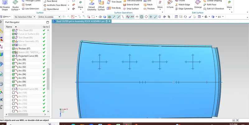
An automobile roof or car top is the portion of an automobile that sits above the passenger compartment, protecting the vehicle occupants from sun, wind, rain, and other external elements. Because the earliest automobiles were designed in an era of horse down carriages early automobile roofs used simila materials and designs.
The roof also ensures the safety of the passengers from the obstacle or during the collision by imposoing proper roof rails
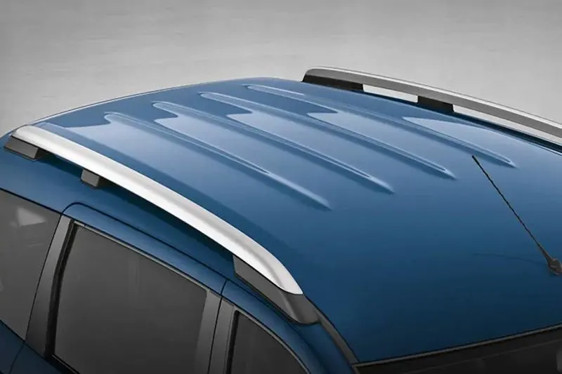
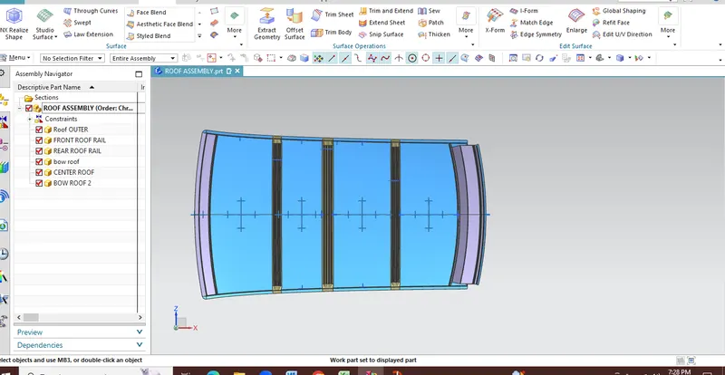
The Automobile roof consists of the following parts:
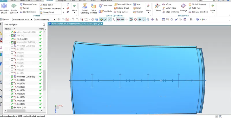
- The outer panel
- Front roof Rail
- Bow Roof
- Centre Roof Rail
- Rear Roof Rail
FRONT ROOF RAIL :
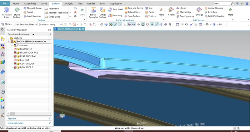
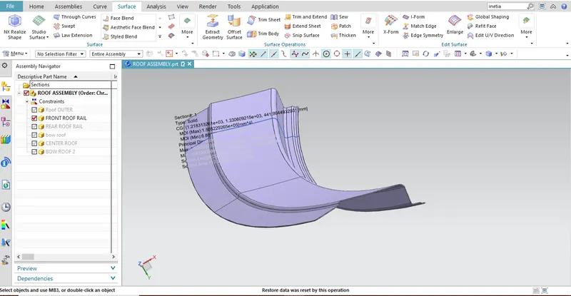
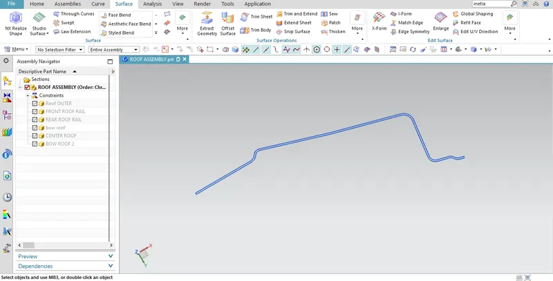
Front roof rail is the one which joins the wind shield glass , body side outer and the inner panel also. Here the front roof rail is designed based up on the master saection given
REAR ROOF RAIL :
Rear roof rail is the one which joins the back door and the body side outer
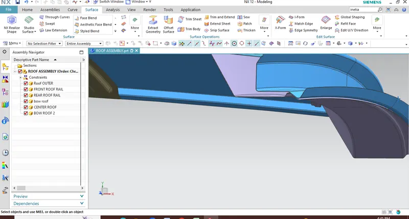
BOW ROOF 1:
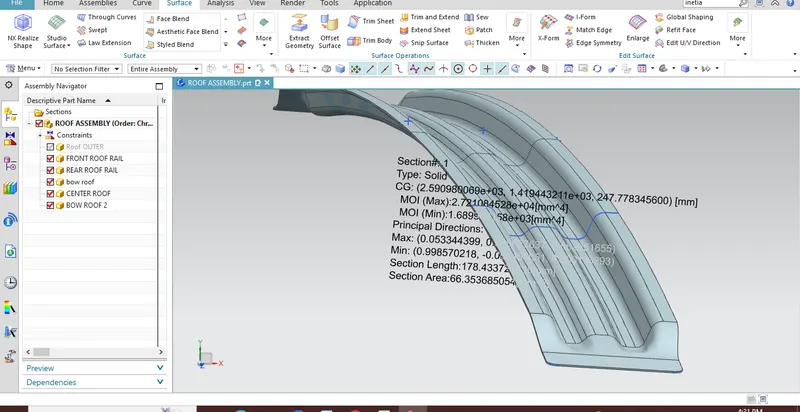
Bow roof center 1 is an additional stiffening member used in the roof assembly for the localised strength improvement and it is join directly to roof itself with several spot welding or even with mastic sealent.
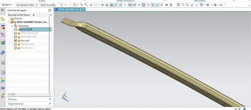
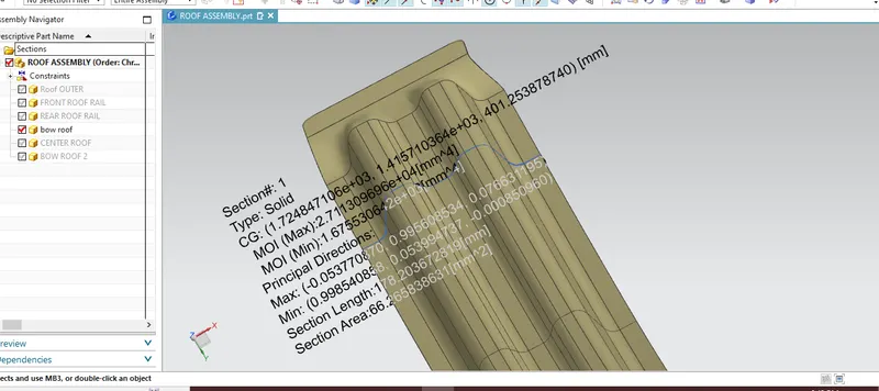
Central Roof rail:
Central roof rail helps in providing effectively support to the flat area of the roof as it is more susceptible to failure under the action of load. Generally central roof rail is placed at the center of the roof which is connected to the B-pillar support structure. This central roof rail helps in the strength to the roof during the roll-over test.
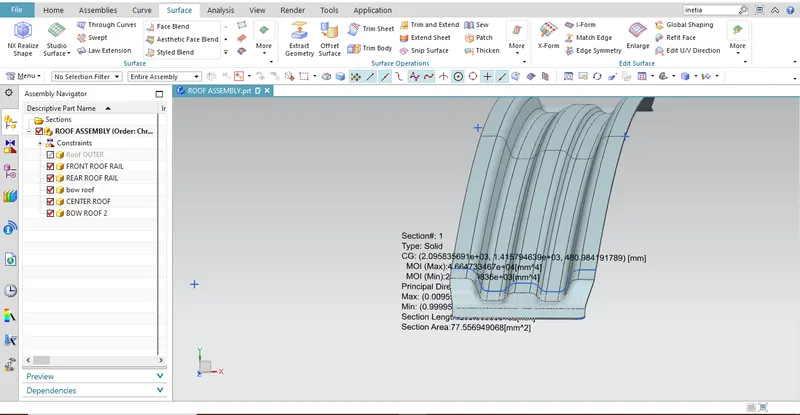
BOW ROOF 2:
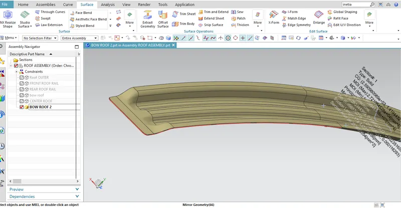
It is similar to that of bow roof 1 which serves the same purpose as the previous but with a limited extend and hence it is used with a smaller cross.
Heat Distortion Calculations:
We have a data to calculate
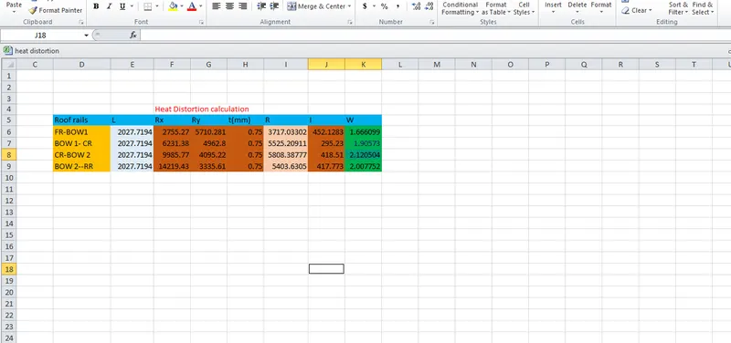
W = [1.73 x 10^(-3) x L] + [1.85 x 10^(-8) x (R^2)/t] + [ 1.10x10^(-3) x l] - 2.68
Judgement Condition : OK< 2.7> 3.1
Where
L = Roof Length in X-Direction[mm](Roof dimension in 0-Y)
R = Roof curvature
R = 2(Rx*Ry)/(Rx+Ry)
Rx = X curvature
Ry = Y curvature
t = Roof plate thickness [mm]
l = Bow Roof Span [mm]
Here
- 'l' value is from one reinforcement centre to other reinforcement centre value.
- 'L' value is total length from one end to another end.
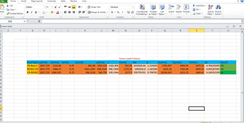
According to the judgement criteria OK< 2.7> 3.1, All values are satisfied.
Snow Load Calculations:
We have a data to calculate
Qr = [Iy x t2] / [α x s x [(Rx + Ry)/2]2 x 10-8]
Note: The Qr value given over here is correct. There was a typo error in the formula given in the video.
Where
α = My x Lx2 x 10-12 , My = Y(Ly-Y)
Judgement condition = Qr ≥ 3.1
250 ≤ s ≤ 380
t = Roof plate thickness [mm]
Ly = Distance between the front and rear roof Rails on the Vehicle along with 0Y[mm]
Length of Roof panel with the center point between Roof rail Front /Rear as the front and rear reference point.
Lx = Distance between the Left and Right end of the roof on the Roof BOW [mm]
Width of the roof panel exposed on the surface.
Y = Distance front Front Roof Rail to Roof BOW[mm]
s = Distance for which Roof BOW bears divided load [mm]
s = L1/2 + L2/2
Iy = Geometrical moment of inertia of Roof BOW (Y cross-section )[mm4]
Rx = Lateral direction curvature radius of roof panel Y cross-section on Roof BOW [mm]
Roof panel curvature Radius of the Length Lx in Front view
Ry = Longitudinal Direction curvature radius of the Roof panel X cross-section on Roof BOW [mm]
Roof panel X curvature radius of length s in Side view
Conclusion:
The roof was created with all required parameters with a certain rails, and calculation the heat distortion, snow load are done and performed Draft analysisfor safety concerns. The result is satisactory.