Roof Design
AIM :
To design the complete roof from styling to a completed Roof with Bow roofs, Front and Rear Panel, and Centre reinforcement for Roof strength then perform Draft Analysis, Inertia analysis, and Load Calculations.
CAR ROOF:
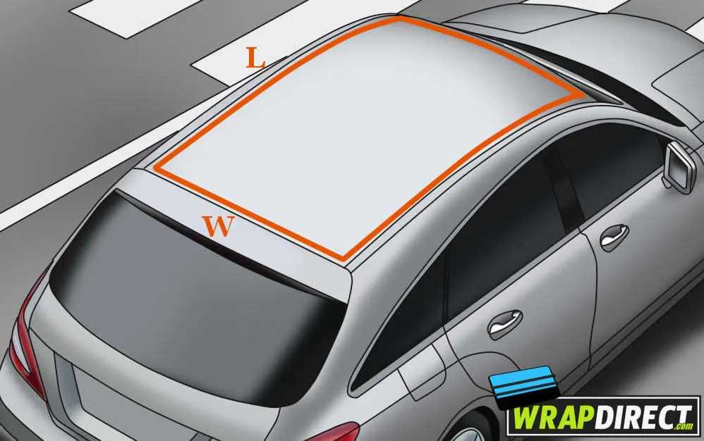
The car roof, also known as the car's top or ceiling, is the uppermost part of the vehicle that covers and encloses the passenger compartment. The car roof serves several purposes, including:
-
Protection from weather elements: The car roof provides protection from rain, snow, wind, and sun, keeping the passengers inside the car dry and comfortable.
-
Structural support: The roof of the car adds strength and stability to the vehicle's overall structure, helping to distribute weight evenly and maintain the car's structural integrity.
-
Acoustic insulation: The roof of the car helps to reduce noise levels from outside, making the ride inside the car quieter and more comfortable.
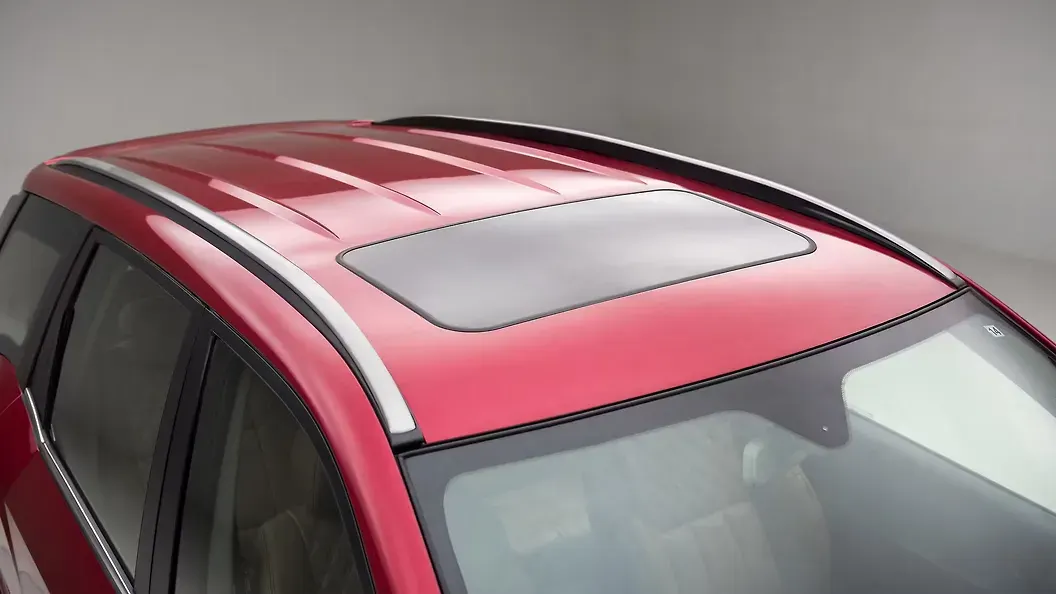
Car roofs can be made from various materials, such as steel, aluminum, carbon fiber, or composite materials. Some cars also have sunroofs or moonroofs, which are small windows in the roof that can be opened or closed to provide fresh air and natural light to the car. Convertible cars have retractable roofs that can be lowered or raised, allowing passengers to enjoy an open-air driving experience.

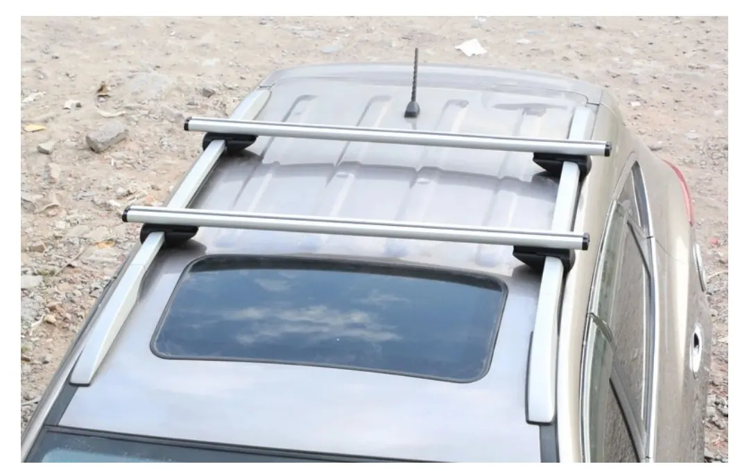
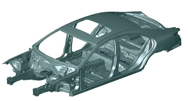
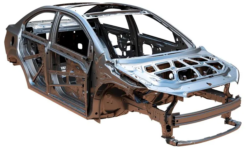
Roof rails BIW:
Car Styling( Class A) :
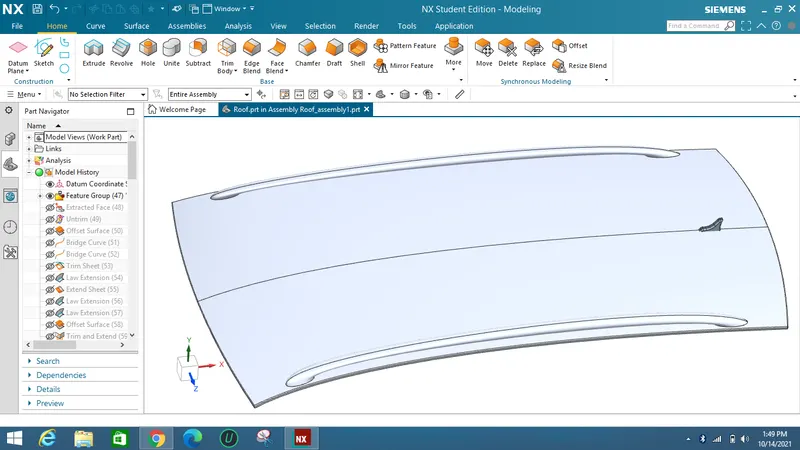
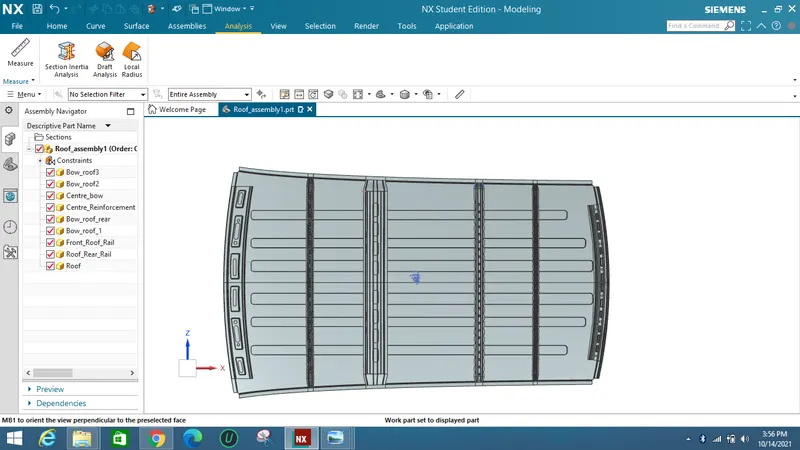
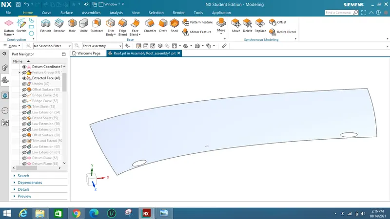
As a raw data a car roof is given as a styling from a Class A team as shown below.
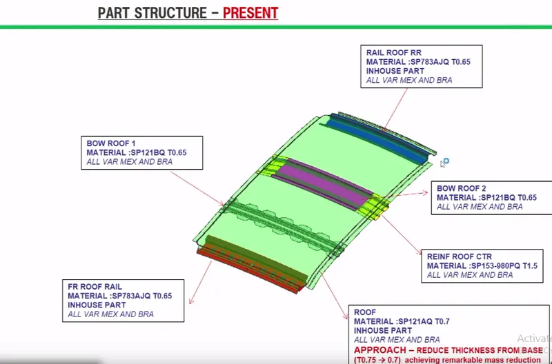
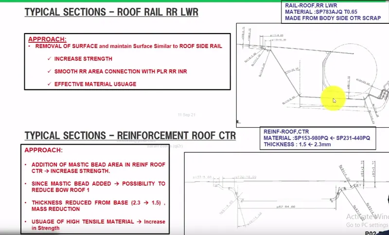
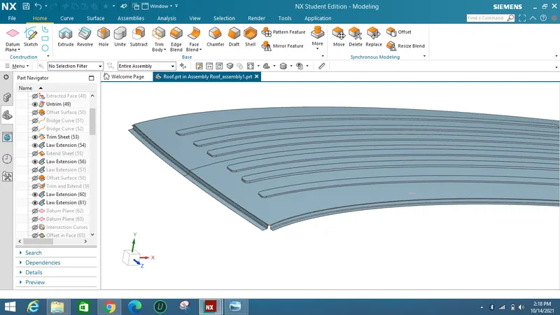
There are typical sections like Front, Rear panel, Bow roofs and centre reinforcement for Roof strength.
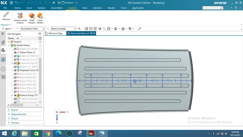
The basic overview and part sections of a roof will looks like below image 1 :
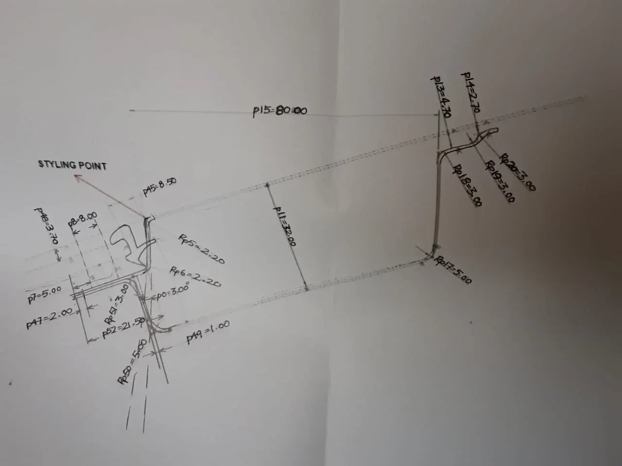
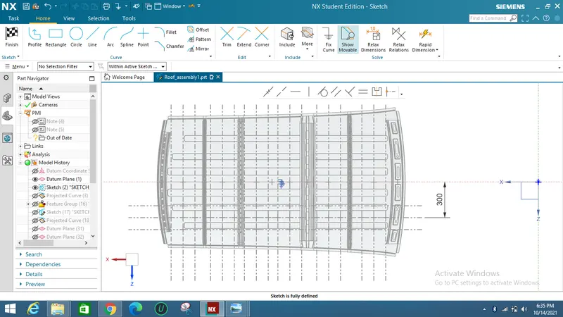
The assumption of the Bow and centre bow sketches are given below :
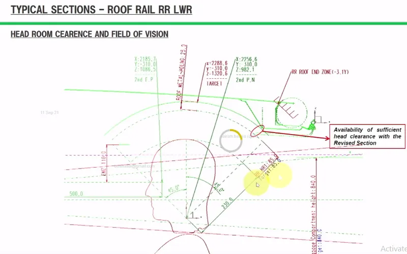
The front roof rail and the bow roof 1 is designed in a manner that does'nt leave a obstruction to the vision of a driver.
ROOF FLANGE DESIGN:
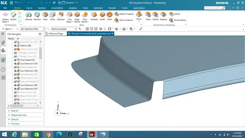
Roof flange design is an important aspect of car roof design. The flange is the area where the roof panel meets the body of the car, and it plays a critical role in maintaining the structural integrity of the car and preventing water leakage.
The design of the roof flange depends on several factors, including the materials used, the manufacturing process, and the desired aesthetics. In general, the flange should be designed to provide a strong and secure connection between the roof panel and the car body, while also ensuring that water and other elements do not penetrate the passenger compartment.
One common approach to roof flange design is to use a hemmed flange. This involves folding the edge of the roof panel over onto itself and then clamping it to the body of the car. The hemmed flange provides a strong and secure connection that resists separation and helps to prevent water infiltration.
Another approach to roof flange design is to use an adhesive bond. This involves applying a special adhesive between the roof panel and the body of the car, creating a strong and waterproof seal. Adhesive bonds can be particularly effective in situations where the roof panel is made from lightweight or composite materials that may be difficult to hem.
Overall, the design of the roof flange is an important consideration in car roof design, and engineers must carefully evaluate various options to ensure that the roof provides adequate strength, water resistance, and aesthetic appeal.
Draft Analysis :
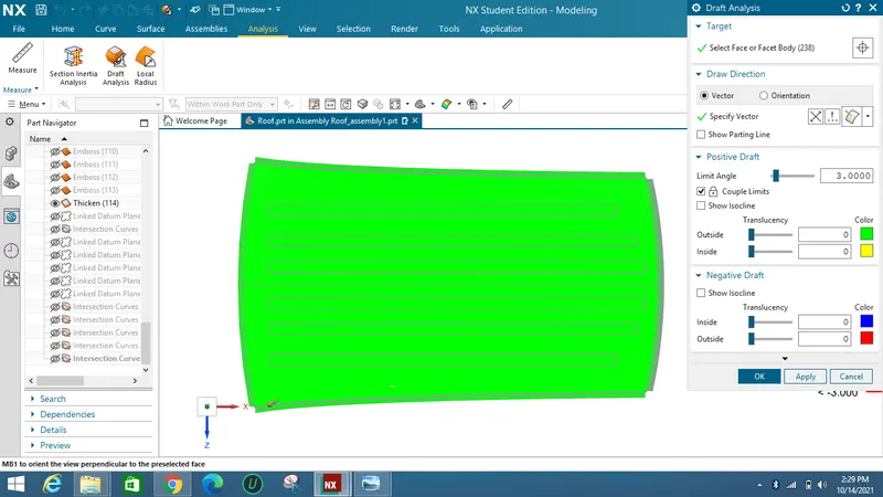
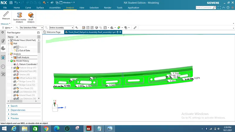
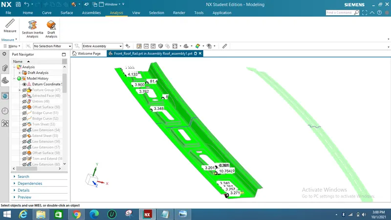
As per the standards the angle maintained for obtaining a exact punch a 3 degree minimum is maintained.
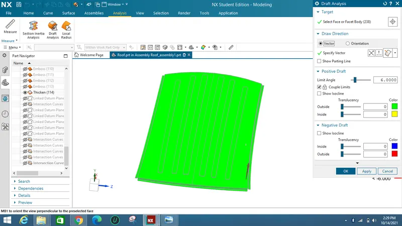
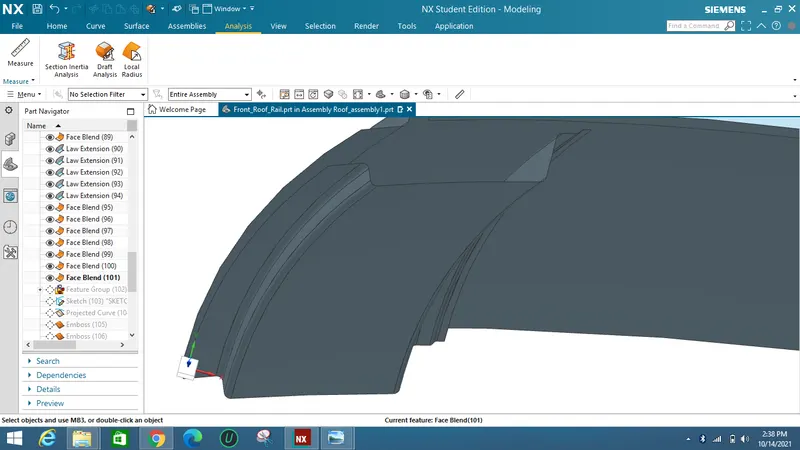
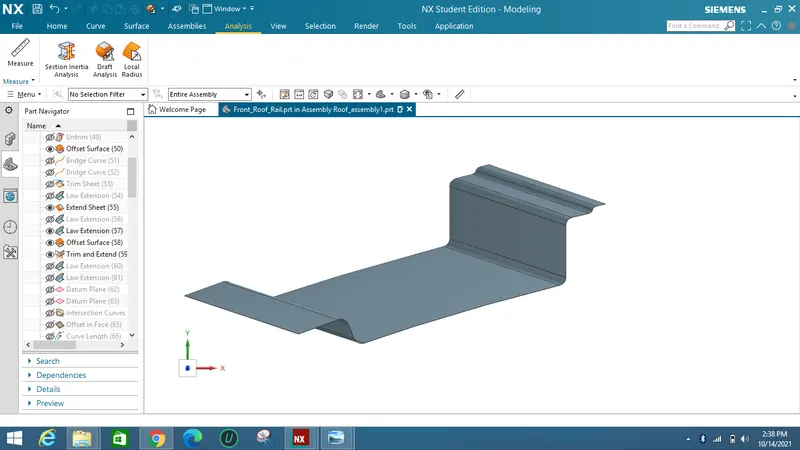
Front Roof rail Design :
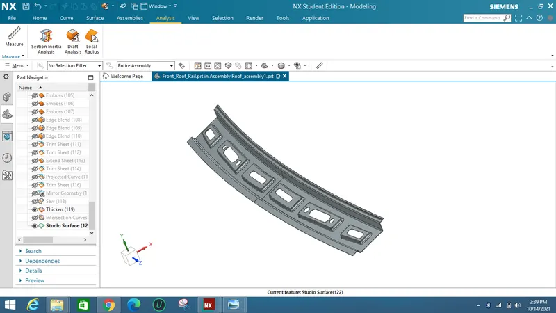
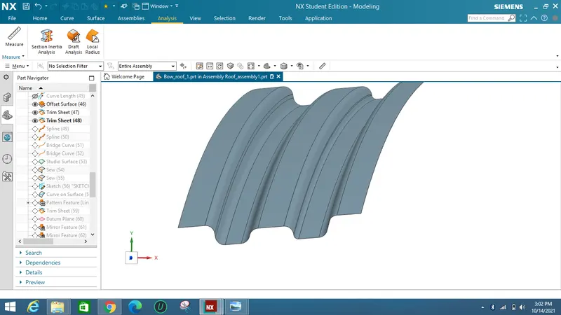
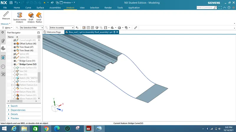
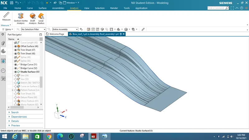
As referring to the Front rail sketch Front roof rail is designed.
By making offsets and law extensions Roof rail is designed with maintaining of 7 degree draft.
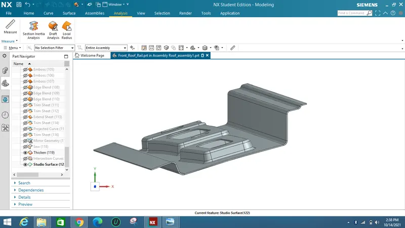
Embosses were added for strengthening the part.
Draft Analysis :
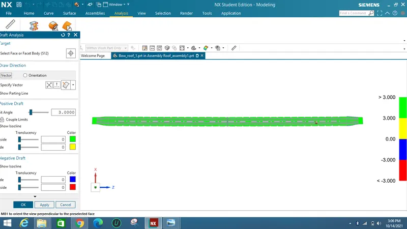
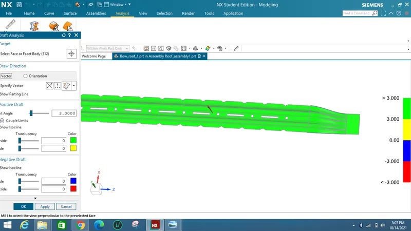
As from the standard sheetmetal criteria a minimum 3 degree of draft angle should be provided on the sheet metal.
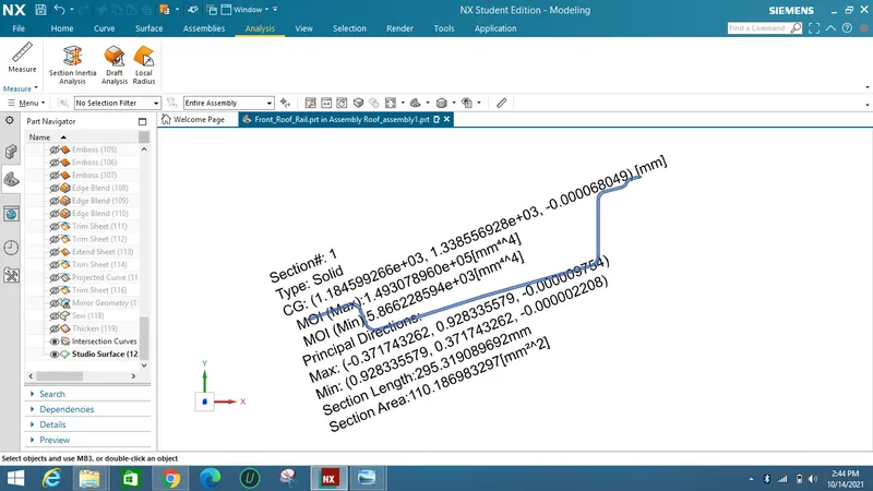
Section Inertia Analysis :
As from the below image the min Inertia value obtained is I = 5866 mm^4 where the load starts effectively.
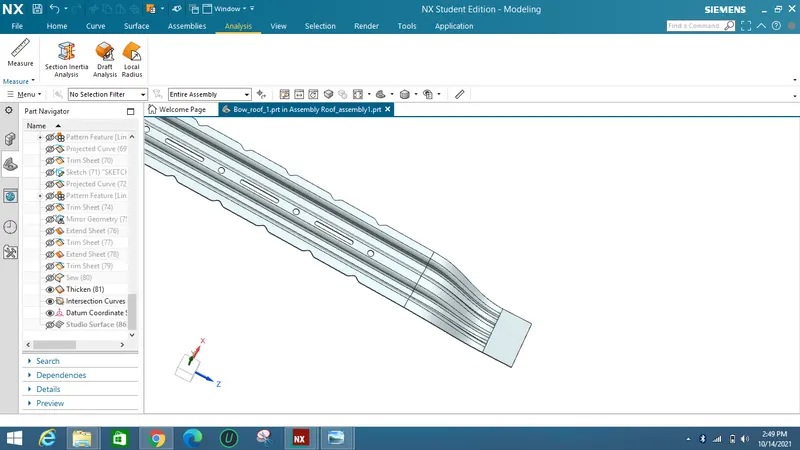
Bow Roof 1:
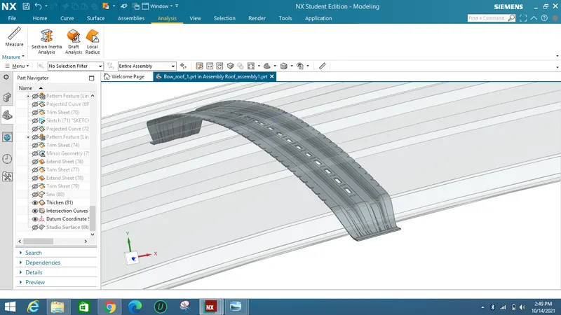
Below is the reference master section given for designing a bow roof :
The above is a roof and the below master section referred as a Bow roof for strengthening roof.
Draft Analysis :
As from the standard sheetmetal criteria a minimum 3 degree of draft angle should be provided on the sheet metal.
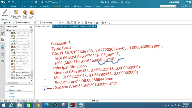
Section Inertia Analysis :
As from the below image the min Inertia value obtained is I = 110 mm^4 where the load starts effectively.
CentreRoof Reinforcement :
Below is the reference master section given for designing a Centre roof reinforcement :
The above is a roof and the below master section referred as a Bow roof for strengthening roof.
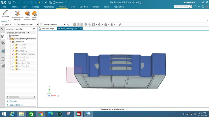
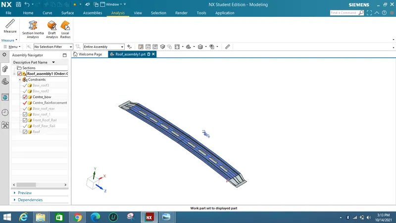
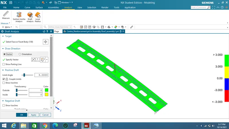
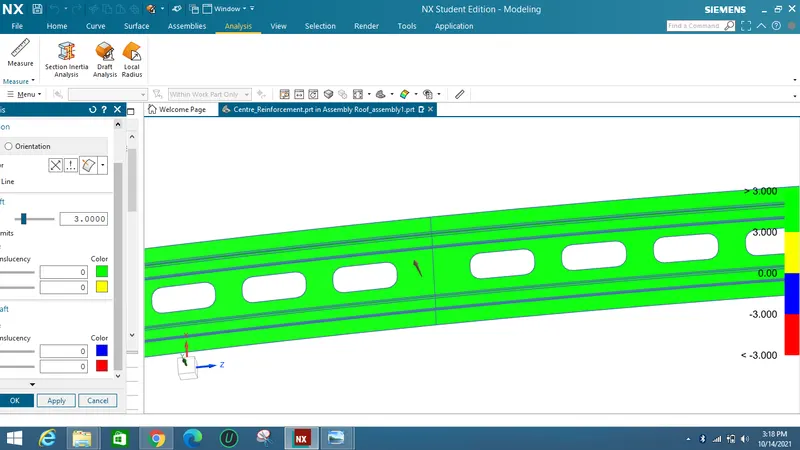
Draft Analysis :
Centre Bow :
As from the standard sheetmetal criteria a minimum 3 degree of draft angle should be provided on the sheet metal.
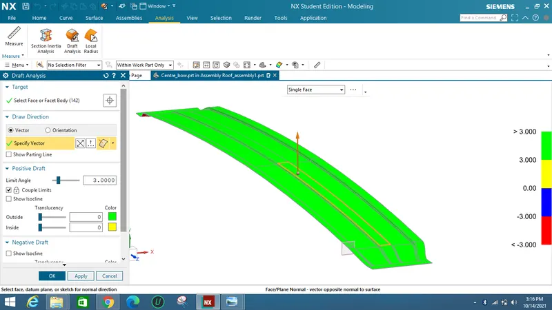
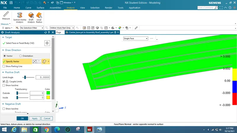
Centre Reinforcement :
As from the standard sheetmetal criteria a minimum 3 degree of draft angle should be provided on the sheet metal.
Section Inertia Analysis :
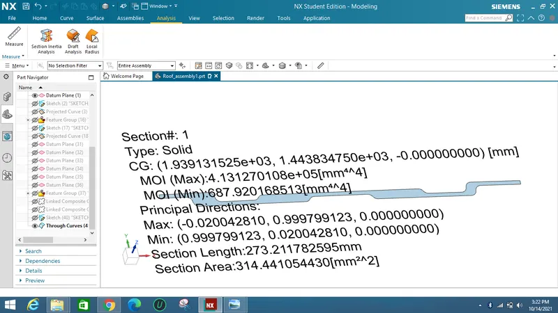
The Section Inertia Analysis for total Bow and Reinforcement is :
The value at which the load acts effectively is I = 687 mm^4
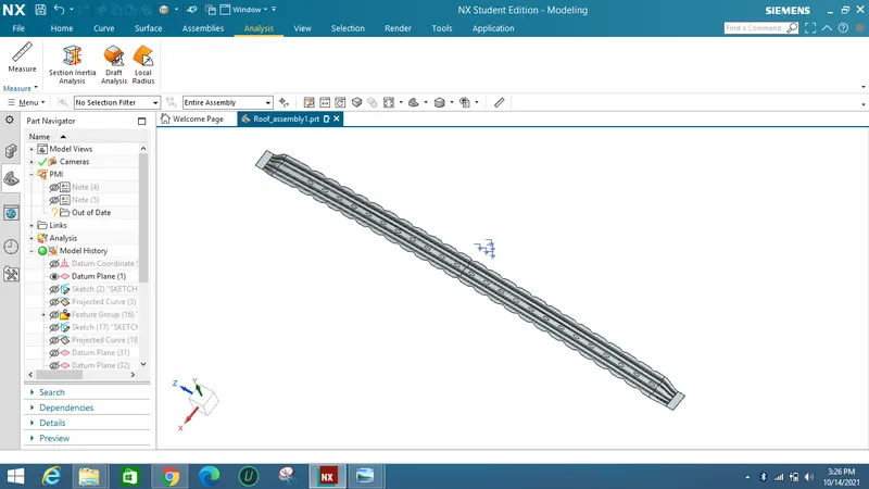
Bow Roof 2 :
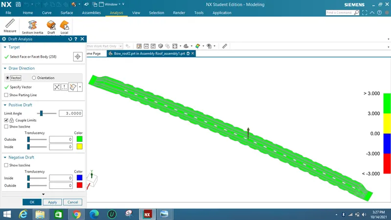
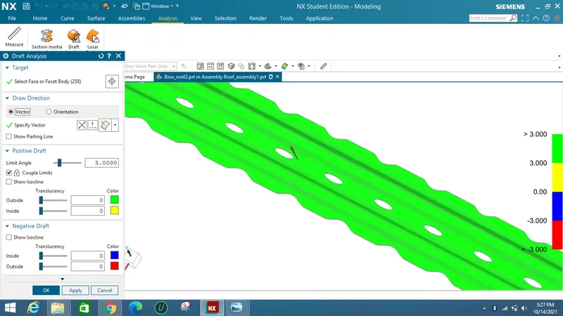
Draft Analysis :
The minimum draft angle required is 3 degree for sheet metal.
Section Inertia Analysis :
The value at which the load acts effectively is I = 152 mm^4.

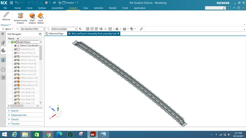
Bow Roof 3 :
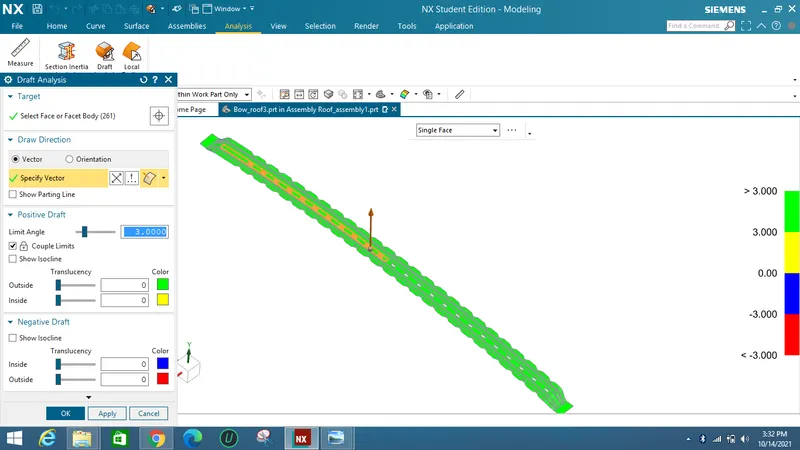
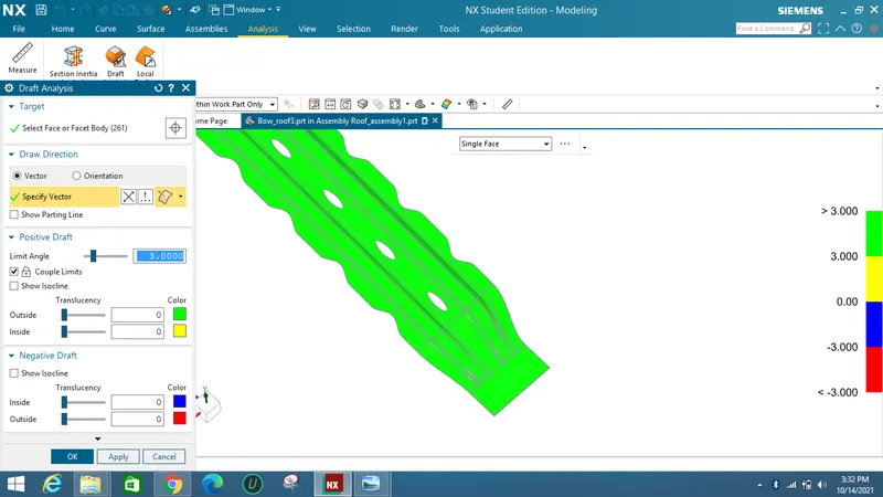
Draft Analysis :
The minimum draft angle required is 3 degree for sheet metal.
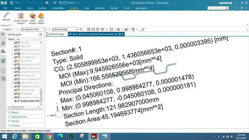
Section Inertia Analysis :
The value at which the load acts effectively is I = 166 mm^4.
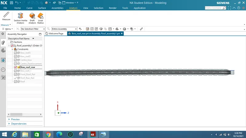
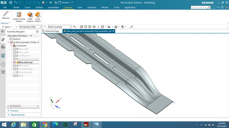
Bow Roof 4 :
Draft Analysis :
The minimum draft angle required is 3 degree for sheet metal.
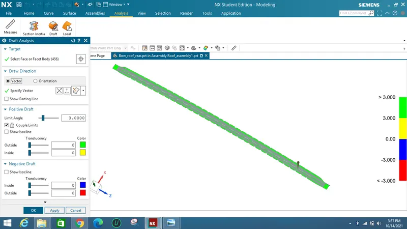
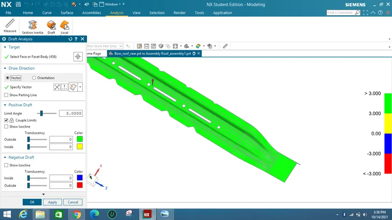
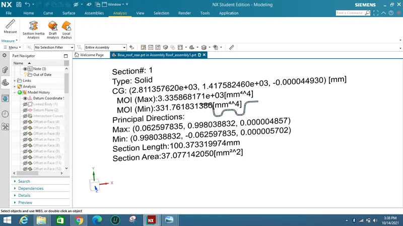
Section Inertia Analysis :
The value at which the load acts effectively is I = 331 mm^4.
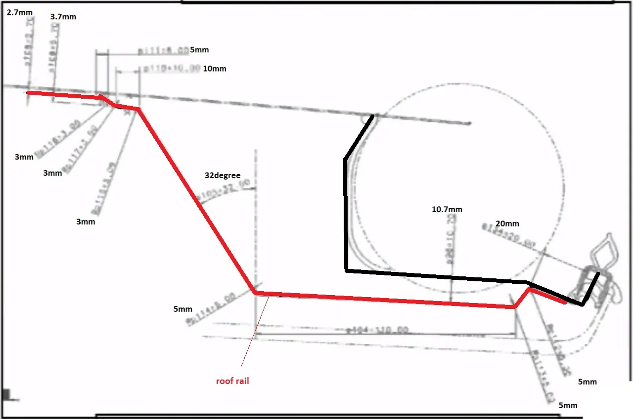
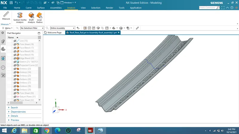
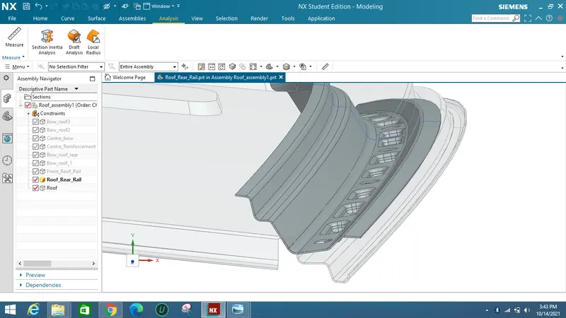
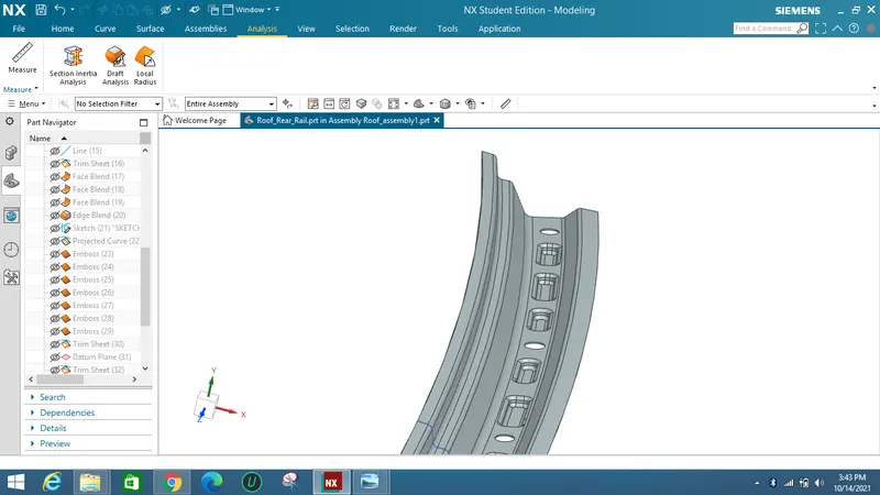
Rear Roof rail Design :
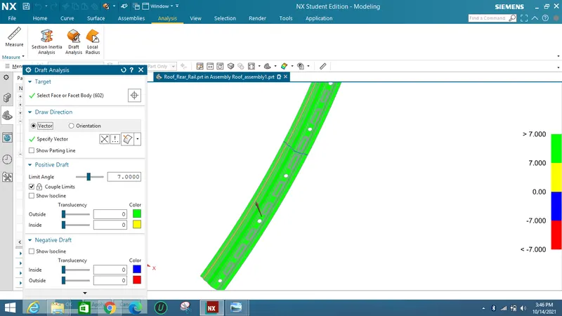
As referring to the Rear rail sketch Front roof rail is designed.
By making offsets and law extensions Roof rail is designed with maintaining of 3 degree draft.
Embosses were added for strengthening the part.
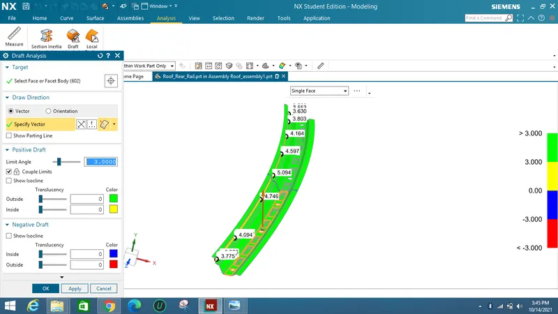
Draft Analysis :
As from the standard sheetmetal criteria a minimum 3 degree of draft angle should be provided on the sheet metal.
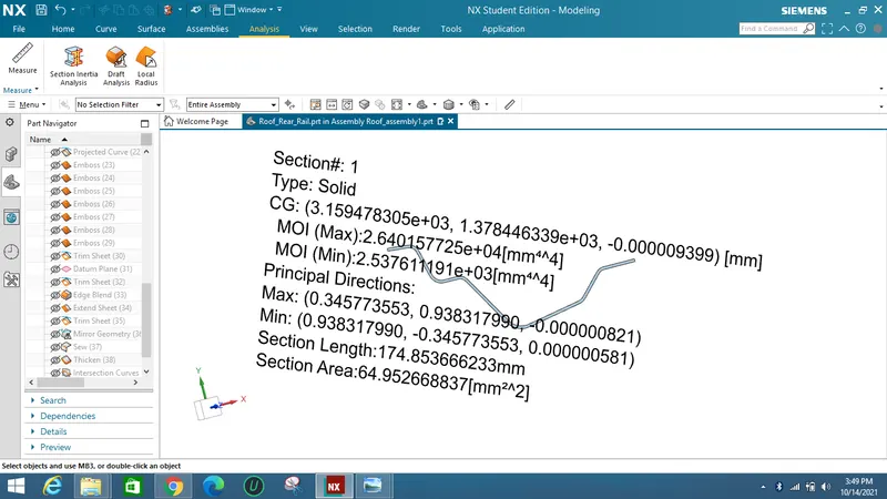
Section Inertia Analysis :
The value obtained where minimum load taking capacity starts is I = 2537 mm^4.
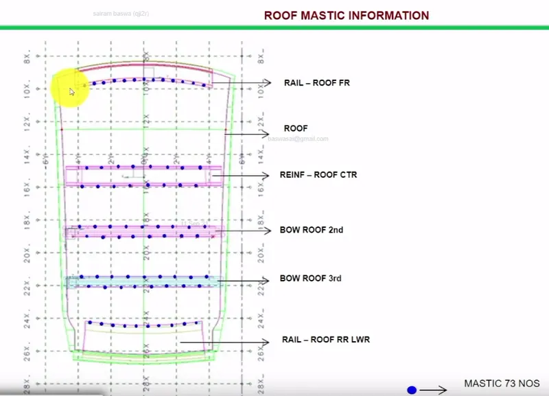
As per the design there should be minimum 5mm gap for mastic points so that roof rails and Bows are attached to roof.
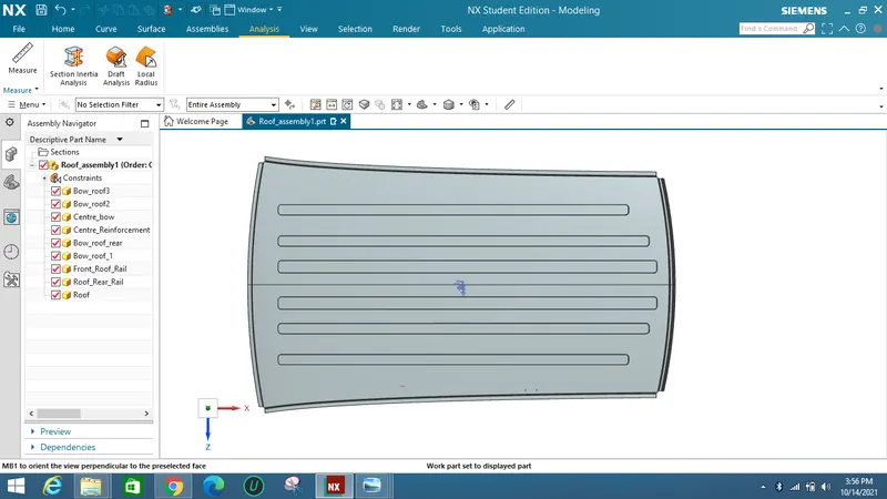
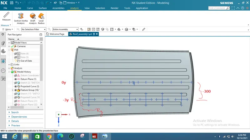
Curvature study on the roof and perform calculations to determine the position of the Bow-roof :
Performing a curvature study on the roof and determining the position of the bow-roof requires a detailed understanding of the car's design and construction. However, in general, the curvature study involves analyzing the shape and curvature of the roof panel to determine the degree of curvature, radius of curvature, and other key parameters. This information can then be used to calculate the position and dimensions of the bow-roof, which is typically located in the center of the roof panel.
To perform the curvature study, engineers may use specialized software and tools to create a digital model of the car roof and analyze its shape and curvature. This may involve using 3D modeling software to create a digital representation of the car roof, and then using mathematical algorithms and other tools to analyze its shape and curvature.
Once the curvature study is complete, engineers can use the results to calculate the position of the bow-roof. The position of the bow-roof is typically determined based on the curvature of the roof panel and the desired shape and appearance of the car.
Calculations may involve determining the appropriate radius of curvature for the bow-roof, as well as the distance and angle of the bow-roof relative to the front and rear of the car. Other factors, such as the materials used in the construction of the roof and the manufacturing process, may also influence the position and dimensions of the bow-roof.
Overall, performing a curvature study on the roof and determining the position of the bow-roof is a complex process that requires specialized knowledge and expertise in car design and engineering.
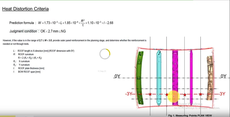
Bow–roof prediction Formula :
W = [1.73 x 10^(-3) x L] + [1.85 x 10^(-8) x (R^2)/t] + [ 1.10x10^(-3) x l] - 2.68
Judgement Condition : OK< 2.7> 3.1
Where
L = Roof Length in X-Direction[mm](Roof dimension in 0-Y)
R = Roof curvature
R = 2(Rx*Ry)/(Rx+Ry)
Rx = X curvature
Ry = Y curvature
t = Roof plate thickness [mm]
l = Bow Roof Span [mm]
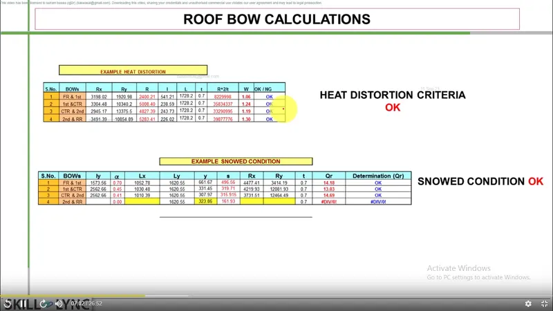
Heat Distortion Results :
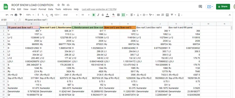
For the above given condition the value should be < 3.1 so that the position of bow roofs can be considered as qualified.
The calculated values of Excel sheet is given below :
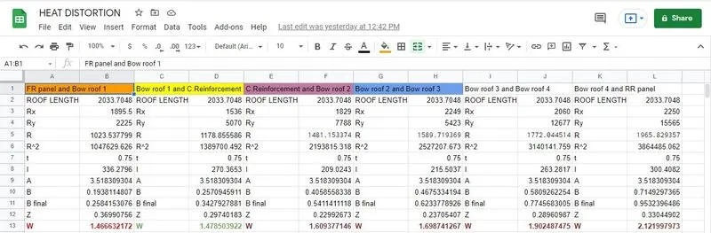
Therefore the placement of Bow roofs can be considered for Load Analysis.
SNOW LOAD PREDICTION FORMULA :
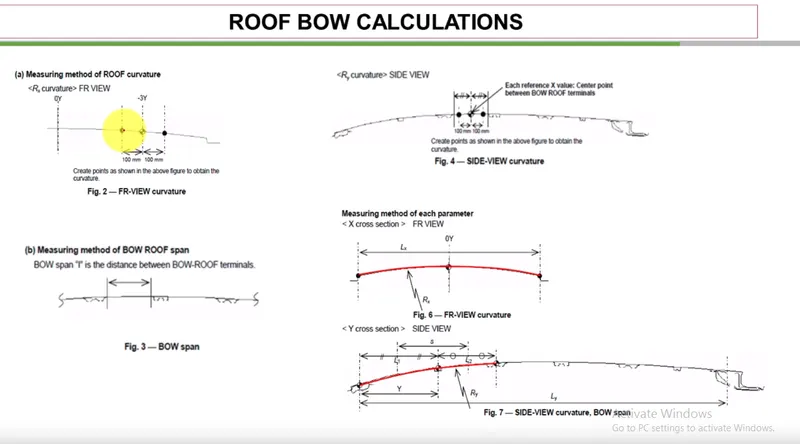
Qr = [Iy x t2] / [α x s x [(Rx + Ry)/2]2 x 10-8]
Note: The Qr value given over here is correct. There was a typo error in the formula given in the video.
Where
α = My x Lx2 x 10-12 , My = Y(Ly-Y)
Judgement condition = Qr ≥ 3.1
250 ≤ s ≤ 380
t = Roof plate thickness [mm]
Ly = Distance between the front and rear roof Rails on the Vehicle along with 0Y[mm]
Length of Roof panel with the center point between Roof rail Front /Rear as the front and rear reference point.
Lx = Distance between the Left and Right end of the roof on the Roof BOW [mm]
Width of the roof panel exposed on the surface.
Y = Distance front Front Roof Rail to Roof BOW[mm]
s = Distance for which Roof BOW bears divided load [mm]
s = L1/2 + L2/2
Iy = Geometrical moment of inertia of Roof BOW (Y cross-section )[mm4]
Rx = Lateral direction curvature radius of roof panel Y cross-section on Roof BOW [mm]
Roof panel curvature Radius of the Length Lx in Front view
Ry = Longitudinal Direction curvature radius of the Roof panel X cross-section on Roof BOW [mm]
Roof panel X curvature radius of length s in Side view.
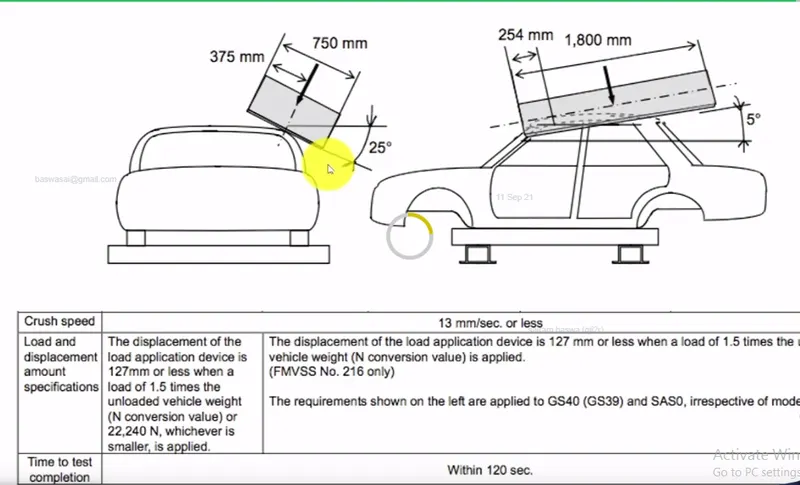
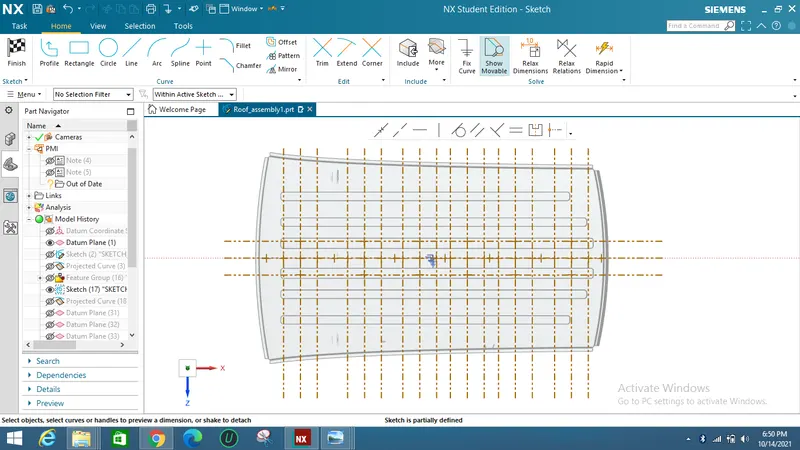
The calculated excel sheet values were shown below :