Roof Design
CAR ROOF DESIGN
ROOF DESIGN OBJECTIVE .
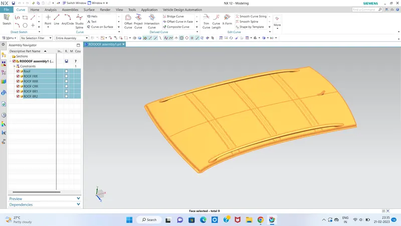
*The objective of this project is to design car roof with essential flanges and reinforcements like ditch area , front roof rail , bow roofs, central roof rail and rear roof rail for the the given styling surface Perform a curvature study on the roof and perform the calculations…
car roof image...
CAR ROOF :
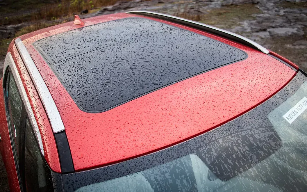
An automobile roof or car top is the portion of an automobile that sits above the passenger compartment, protecting the vehicle occupants from sun, wind, rain, and other external elements. Roof is the structure above the wind shield glass having the reinforcements to provide the strength to the overall structure and to with stand the over head forces like snow.....
WHY REINFORCEMENTS :
If the roof is flat it is very weak and cannot able to with stand the forces like snow , so in order to increase the strength of the roof these reinforcements like front roof rail, central roof rail, rear roof rail and the bow roofs are introduced and joined to the flat surface of the roof with the different joining process.....
Different types of reinforcements that the car has are :
- Front roof rail
- Bow roofs
- Central roof rail and
- Rear roof rail......
*FRONT ROOF RAIL
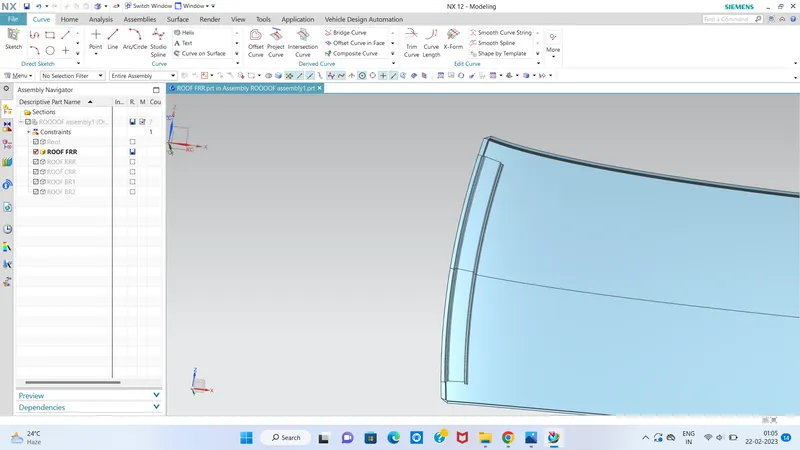
Front roof rail is provided at the front end of the roof to provide strength to that area of roof, while designing this part we should maintain the visibility and headroom clearance. Embosses are created to strengthen the front roof rail.
*BOW ROOFS :
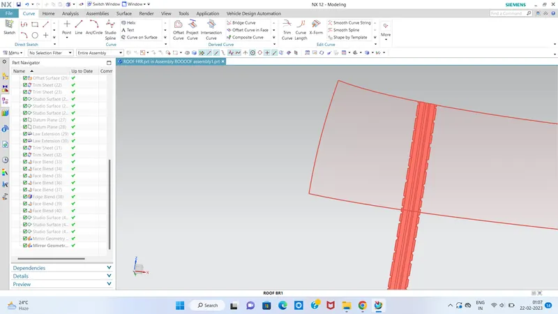
The bow roofs are give to improve the torsional stiffness and load bearing capacity of the roof structure . The number of bow roof present is depends on the overall size of the roof . Presently in this project two bow roofs are added.
CENTER ROOF RAIL
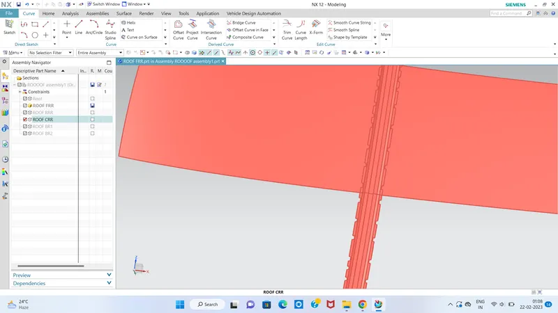
It is provided at the center of the roof to strengthen that area and it is joined to the outer panel by mastic.
REAR ROOF RAIL
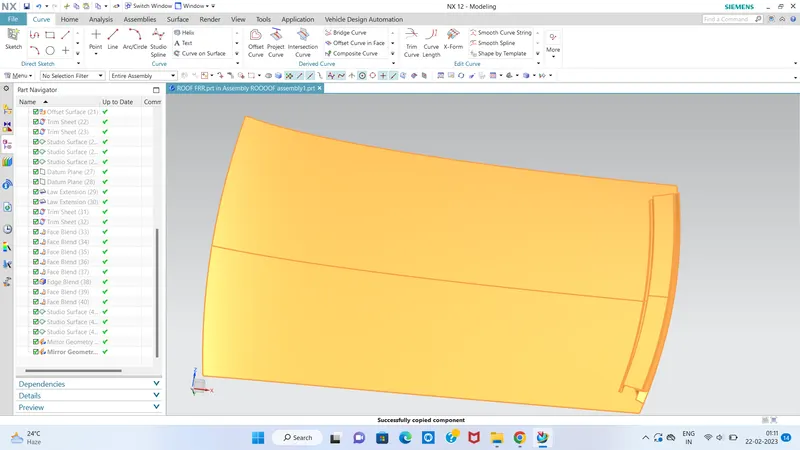
It is provided at the rear part of the roof and it is joined with the outer roof by spot welding. We should take consideration of rear headroom and visibility criteria while desiging this. Embosses are created to strengthen the rear roof rail.
CALCULATIONS.....
FORMULA.....
Bow–Roof Prediction Formula
W = [1.73 x 10^(-3) x L] + [1.85 x 10^(-8) x (R^2)/t] + [ 1.10x10^(-3) x l] - 2.68
Where,
L = Roof Length in X-Direction[mm](Roof dimension in 0-Y)
R = Roof curvature
R = 2(Rx*Ry)/(Rx+Ry)
Rx = X curvature
Ry = Y curvature
t = Roof plate thickness [mm]
l = Bow Roof Span [mm]
Judgment Condition
OK< 2.7
Procedure.....
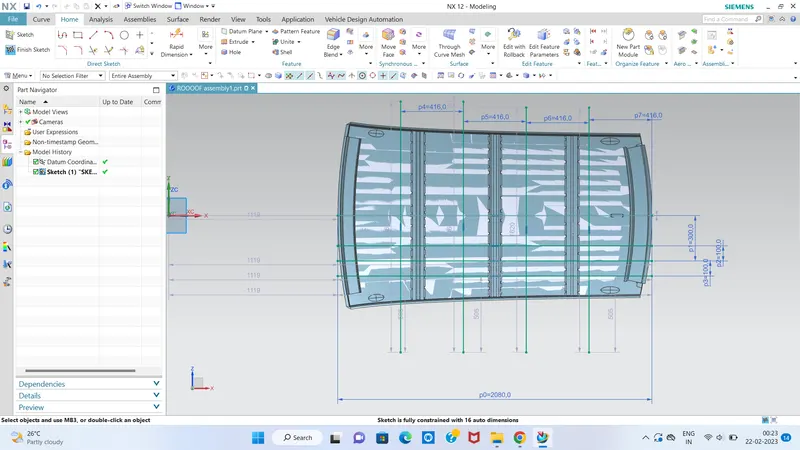
1) We create a 0Y line on the top of the roof.
2)We sketch a -3Y which is 300m below from the 0Y line
3) We sketch 2 line on the both side of the -3Y line at 100mm distance
4) We sketch a line in the middle of the FR and BOW ROOF 1,BOW ROOF 1 and CR, CR and BOW ROOF 2,BOW ROOF 2 and RR.
5) We sketch 2 line on the both sides of the middle line.
6)we create intersection points of the line and project it on the roof then measure the Rx and Ry distance.
CALCULATION....
|
Bow position |
Rx |
Ry |
R |
l |
L |
t |
R2/2 |
W |
OK/NG |
|
FR and 1st |
5626.39 |
3067.66 |
3970.5 |
448.56 |
2033.7 |
1.5 |
21019825.94 |
1.53 |
OK |
|
1st and CTR |
4854.3 |
6624.76 |
5602.99 |
365.81 |
2033.7 |
1.5 |
41858066.77 |
1.63 |
OK |
|
CTR and 2nd |
4065.16 |
10593.91 |
5875.67 |
463.2 |
2033.7 |
1.5 |
46031333.73 |
1.77 |
OK |
|
2nd and RR |
3424.34 |
14478.23 |
5538.68 |
352.33 |
2033.7 |
1.5 |
40902692.46 |
1.6 |
OK |
Snow Load Prediction Formula...
Qr = [Iy x t2] / [α x s x [(Rx + Ry)/2]2 x 10-8]
Note: The Qr value given over here is correct. There was a typo error in the formula given in the video.
Where,
α = My x Lx2 x 10-12 , My = Y(Ly-Y)
t = Roof plate thickness [mm]
Ly = Distance between the front and rear roof Rails on the Vehicle along with 0Y[mm]
Length of Roof panel with the center point between Roof rail Front /Rear as the front and rear reference point.
Lx = Distance between the Left and Right end of the roof on the Roof BOW [mm]
The width of the roof panel is exposed on the surface.
Y = Distance front Front Roof Rail to Roof BOW[mm]
s = Distance for which Roof BOW bears divided load [mm]
s = L1/2 + L2/2
Iy = Geometrical moment of inertia of Roof BOW (Y cross-section )[mm4]
Rx = Lateral direction curvature radius of roof panel Y cross-section on Roof BOW [mm]
Roof panel curvature Radius of the Length Lx in Front view
Ry = Longitudinal Direction curvature radius of the Roof panel X cross-section on Roof BOW [mm]
Roof panel X curvature radius of length s in Side view....
RESULT.....
|
Bow position |
Iy |
α |
Lx |
Ly |
Y |
S |
Rx |
Ry |
t |
Qr |
Determination |
|
FR and 1st |
161.19 |
1.05 |
1119.69 |
2033.7 |
569.65 |
447.74 |
4105.6 |
15113.26 |
1.5 |
0.84 |
NG |
|
1st and CTR |
267.05 |
1.21 |
1081.72 |
2033.7 |
979.65 |
464.47 |
3794.03 |
10543.14 |
1.5 |
2.09 |
NG |
|
CTR and 2nd |
161.3 |
0.91 |
1059.39 |
2033.7 |
1488.08 |
447.71 |
4231.18 |
6602.02 |
1.5 |
3.03 |
NG |
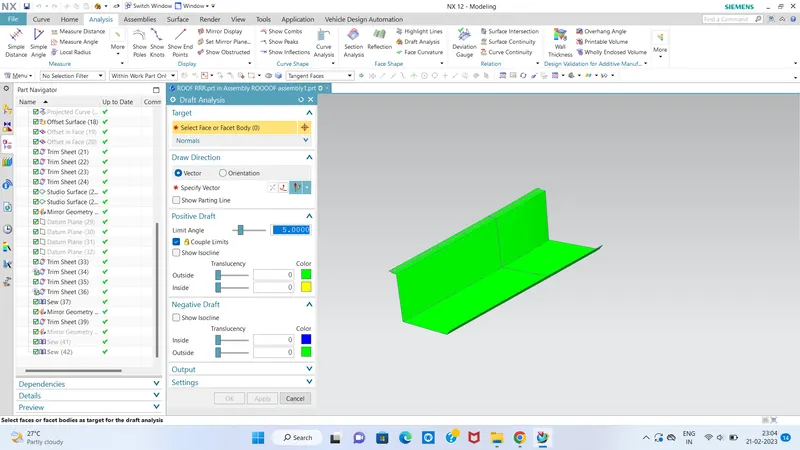
Draft analysis-
Before we give the part for manufacturing we have to some analysis ourself to check all the constraints and to check if we have any negative draft on a part .
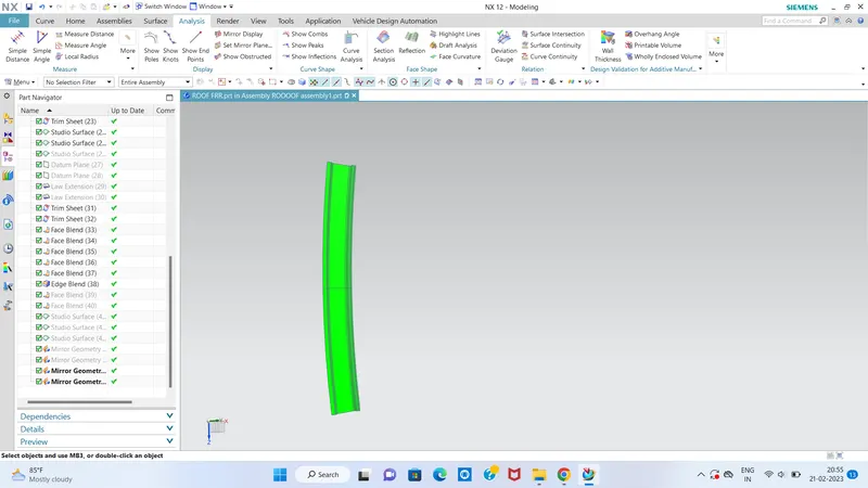
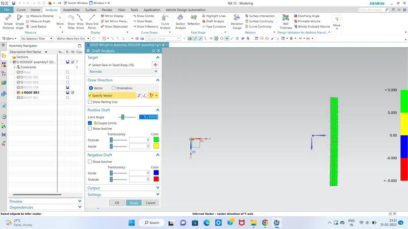
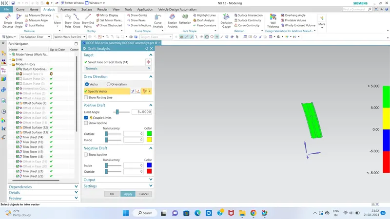
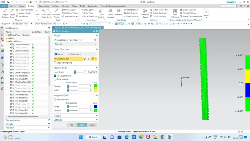
The Draft Analysis command enables you to detect if the part you drafted will be easily removed. This type of analysis is performed based on color ranges identifying zones on the analyzed element where the deviation from the draft direction at any point, corresponds to specified values.
Minimum draft angle of 70 is considered for analysis . green colour infer on the parts that all face along the tooling direction has positive draft angle greater than 70 and passed in analysis
Front roof rail-
Rear roof rail-
Bow roof 1
Centre roof rail-
Bow roof 2
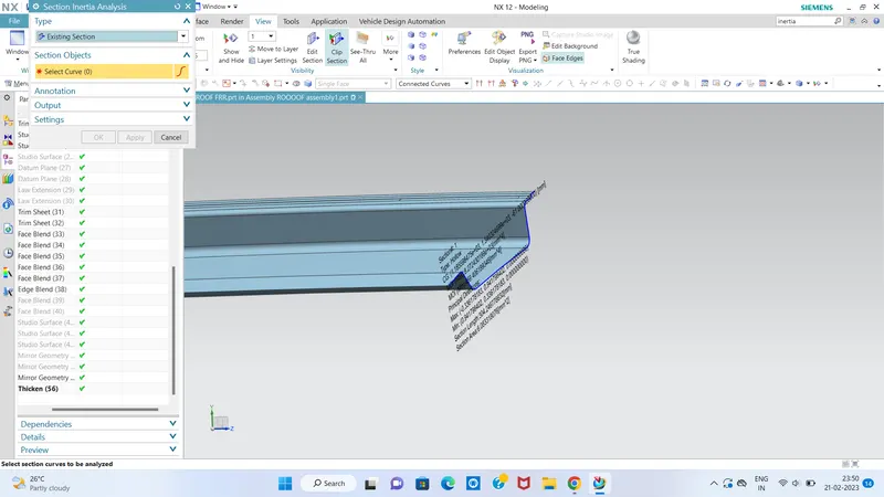
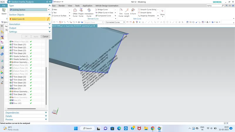
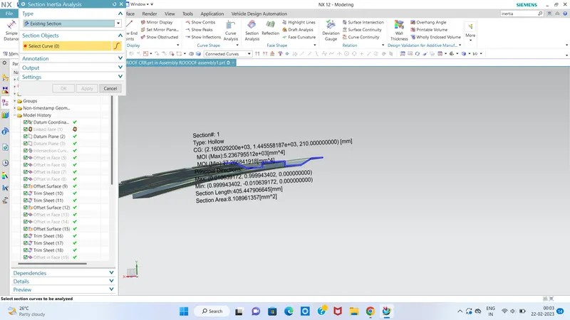
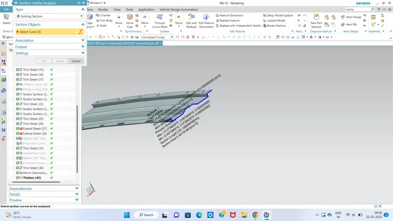
Section analysis:
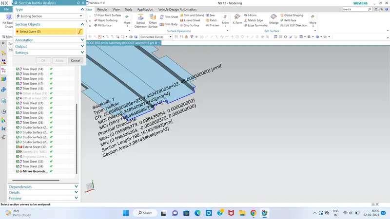
Section moment of inertia is used to predict the amount of deformation and deflection of a part. A higher moment of inertia is preferable as it reduces the amount of deflection for a given force. The thickness of the part and addition of flanges and embosses increase the section inertia of the part. Here the master sections of the roof and roof rails and their section analysis are given.
FRONT ROOF RAIL
REAR ROOF RAIL
Centre bow roof-
Bow roof 1
Bow roof 2
FINAL CAR ROOF DESIGN....