Roof Design
Automobile roof
An automobile roof or car top is the portion of an automobile that sits above the passenger compartment, protecting the vehicle occupants from sun, wind, rain, and other external elements. Because the earliest automobiles were designed in an era of horse drawn carriages, early automobile roofs used similar materials and designs.
Roof Crush Test
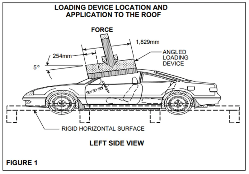
FMVSS 216, Roof Crush Resistance, establishes strength requirements for the passenger compartment roof of passenger cars, multipurpose passenger vehicles, trucks and buses with a GVWR of 2722 kilograms or less. The purpose of the standard is to reduce deaths and injuries due to the crushing of the roof into the passenger compartment in rollover accidents. The standard does not apply to school buses and passenger cars that conform to the dynamic rollover test requirements of FMVSS 208, Occupant Crash Protection, S5.3 by means that require no action by passenger car occupants. It also does not apply to convertibles, except for optional compliance with the standard as an alternative to the rollover test requirements in S5.3 of FMVSS 208. The prescribed static loading device is a rigid unyielding rectangular block 762 millimetres by 1,829 millimetres. It shall not move more than 127 millimetres to achieve the specified resistive load when applied to the forward edge of a vehicle’s roof – see Figures. The resistive load to be achieved is 1½ times the unloaded vehicle 2 weight (UVW) of the test vehicle or 22,240 Newtons, whichever is less. Both the left and right front portions of the vehicle's roof structure shall be capable of meeting the requirements but a particular passenger car need NOT meet further requirements after being tested at one location. The passenger car's sills shall be placed on a rigid horizontal surface and fixed rigidly in position. The vehicle's windows shall be closed and the doors shall be locked. Any convertible top or removable roof structure shall be secured in place over the occupant compartment. Remove roof racks or other non-structural components. The force shall be applied in a downward direction perpendicular to the lower surface of the static loading device at a rate of not more than 13 millimetres per second until reaching the compliant resistive load. The test shall be completed within 120 seconds. The static loading device shall be guided throughout the test so that it moves, without rotation, in a straight line with its lower surface oriented as follows and as shown in Figure. Its longitudinal axis is at a forward angle (side view) of 5º below the horizontal, and is parallel to the vertical plane through the vehicle's longitudinal centreline. B. Its lateral axis is at a lateral outboard angle, in the front view projection, 25º below the horizontal. C. Its lower surface is tangent to the surface of the vehicle. D. The initial contact point, or centre of the initial contact area, is on the longitudinal centreline of the lower surface of the static loading device and 254 millimetres from the forward most point of the centreline. E. If the vehicle being tested is a multipurpose passenger vehicle, truck, or bus that has a raised roof or altered roof, and the initial contact point of the static loading device is on the raised roof or altered roof to the rear of the roof over the front seat area, the plate is positioned so that the midpoint of the rearward edge of the lower surface of the static loading device is within 10 mm of the transverse vertical plane located at the rear of the roof over the front seat area.
Roof Design
Parts of Roof: -
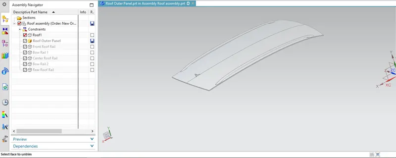
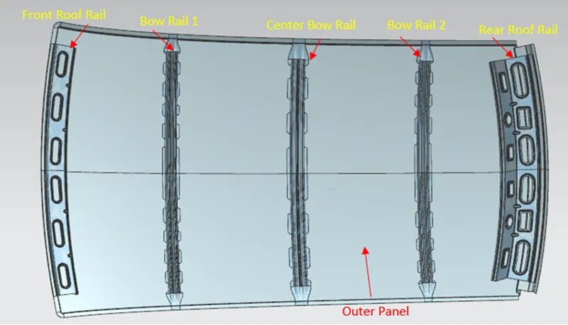
- Outer Roof Panel
- Front Roof Rail
- Bow Roof Rail 1
- Centre Roof Rail
- Bow Roof Rail 2
- Rear Roof Rail
- Extract Surface to work from Styling Surface
Outer panel is provided from the styling team from that extracting the surface to model the necessary reinforcements like Ditch area, Front Roof Rail, Bow Roof Rails, Centre Roof, and Rear Roof Rail.
Design provided from styling team
2. Front and Rear Ditch area design
- The Ditch Area is the extended portion of the main Roof concealed by other BiW panels. The rail supports of the roof are attached to the Ditch Area using Spot welds, since it is not a styling surface and remains concealed.
- The styling team provided the master section for the roof ditch area, front roof rail, and rear roof rail as per the parameter of visibility criteria, headroom clearance, and other important parameter dimensions like fitment of the windshield, sealant rubber, etc.
- Design must be able for easing part manufacturing.
Front Ditch Area.
- Creates ditch area using extracted surface according to master section dimensions.
- The flange of around 15mm was created with the law extension command, corner relief at rear flanges, and a positive draft of more than 3 degrees considering the drawing operation process. The overall thickness of sheet metal considers 0.75mm throughout of Panel.
- The surface is offset from the outer panel to form the ditch area and by using the law extension, corner relief at rear flanges, and positive draft in the required degree considering for the drawing operation process. The overall thickness of sheet metal for the outer panel considers 0.75mm.
- This side walls is further used for creating joining surface for Bow rails.
- To create this surface Bridge curve, Law of extension, edge blend, studio surface and sew command used.
And now Outer Panel is ready.
4. Design of Front Roof Rail
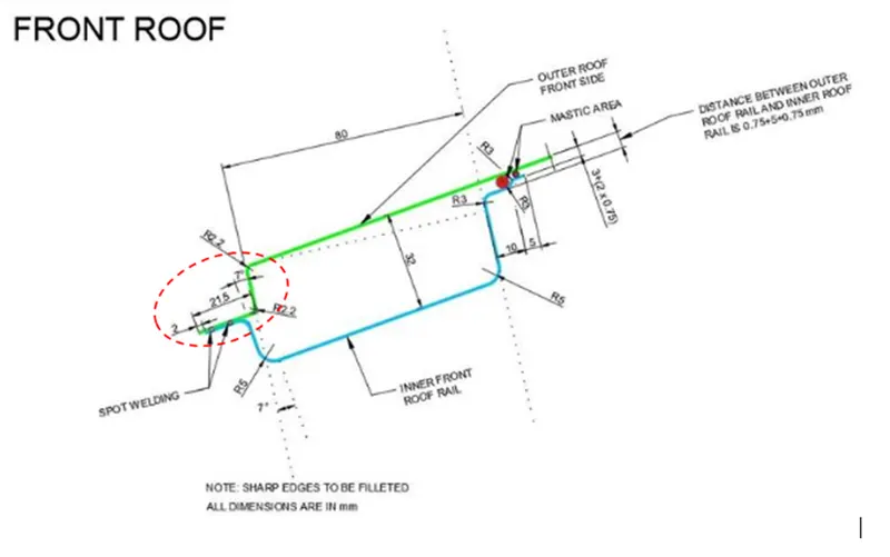
- The front rail underpins the rooftop external shell at the front end. It is mounted with support rooftop rail fortification on the two closures.
- The rails are furnished with embosses and dart to improve the strength over the length and the rail is associated with the external board utilizing mastic sealants on one side and the other joinery is spot welded. It is the support that is joined with the Wind Shield Glass, Body Side Outer, and inner panels.
- It is usually made from Body Side Outer scrap and therefore the thickness of the rail is 0.75 mm. Draft angle must be 3-5 degrees or over.
- The bottommost flange is decided after taking into consideration the visibility criteria and the Headroom Clearance of the passenger.
- Spot Welds are applied at the Windshield end of the rail and the other end is joined with the roof using Mastic Sealants which also contributes to increased strength.
5. Design of Rear Roof Rail
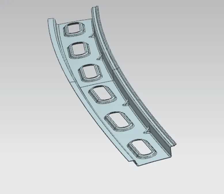
- It is the support that is joined to the Back Door and the Body Side Outer and inner panels.
- As the Front Roof Rail design, we have to take into consideration the rear Headroom Clearance and the rear visibility criteria while designing the Rear Roof Rail. Inputs are taken from the rear master section. It is the support that is joined to the Back Door, the Body Side Outer, and the inner panels. It is also usually made from Body Side Outer scrap and therefore the thickness of the rail is 0.75 mm.
- Similar to the Front Roof Rail design, we have to take into consideration the rear Headroom Clearance and the rear visibility criteria while designing the Rear Roof Rail. Inputs from the backdoor design are also taken to accommodate the required clearance. Spot Welds are applied at the Back door end of the rail and the other end is joined with the roof using Mastic Sealants.
- Also, in this dart and emboss added for strength.
-
6. Design of Bow Roof Rail 1 & 2
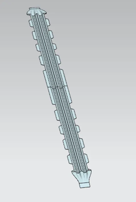
- The Bow roofs are given to improve the torsional stiffness and load-bearing capacity of the roof structure. The number of bow roofs provided will depend upon the overall dimensions of the roof. The longer the roof more the bow roofs are integrated into the BIW frame They are attached to the outer panel using mastic sealants. Each mastic point will have up to 80 mm circular effective area.
- The thickness of the Bow Roof is 0.75 mm and also mastic area has been created.
- In this design roof is consider as without sunroof design so this roof needs two Bow rails.
- Both rails are identical.
7. Design of Centre Roof Rail
- Centre roof rail is provided to effectively support the flat area of the roof as it is more susceptible to failure under the action of the load.
- Usually, the centre reinforcement roof rail will be placed at the centre of the roof connecting the B pillar support structure which results in added support in the roll-over test.
- The thickness of the centre bow roof is 0.75 mm thickness.
- Design drawn by considering master section.
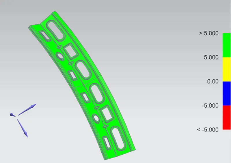
Draft Analysis
Roof Panel
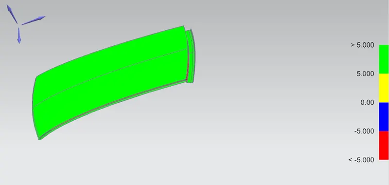
- Front Roof Rail
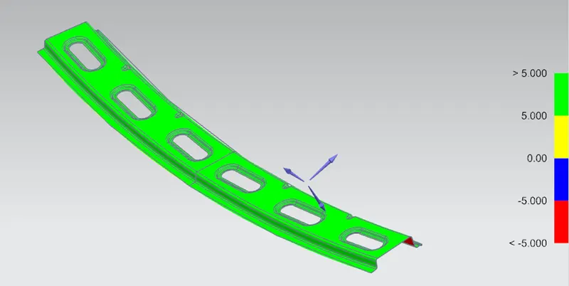
- Centre Bow Rail
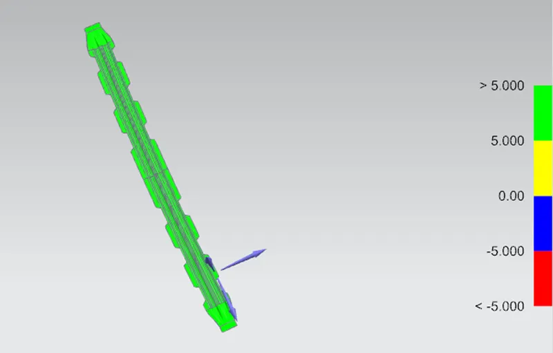
- Rear Roof Rail
Heat Distortion Criteria
- The heat distortion study plays an important role in sheet metal usage. Heat distortion temperature is a temperature limit above which the material cannot be used for structural applications. This study is used to predict the heat distortion temperature at where the material starts to soften when exposed to a fixed load at an elevated temperature. To avoid bending or damage on the roof, based on heat distortion temperature, this study will predict the bow roof position on the roof to strengthen the roof.
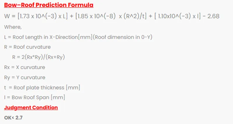
Model Calculation: -
Roof Length (L):
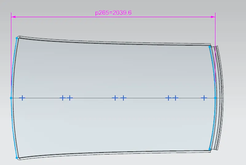
L = 2040 mm
Calculating Rx and Ry:
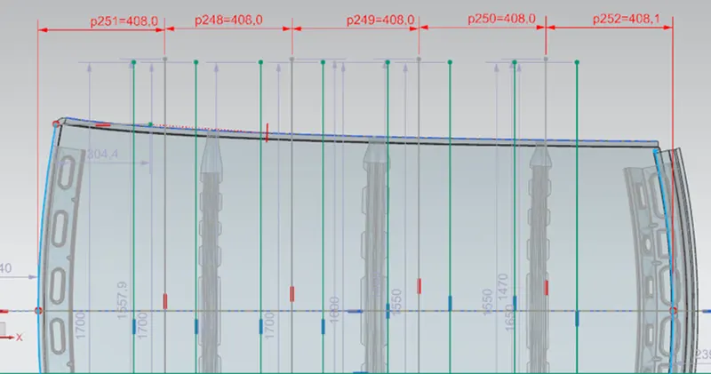
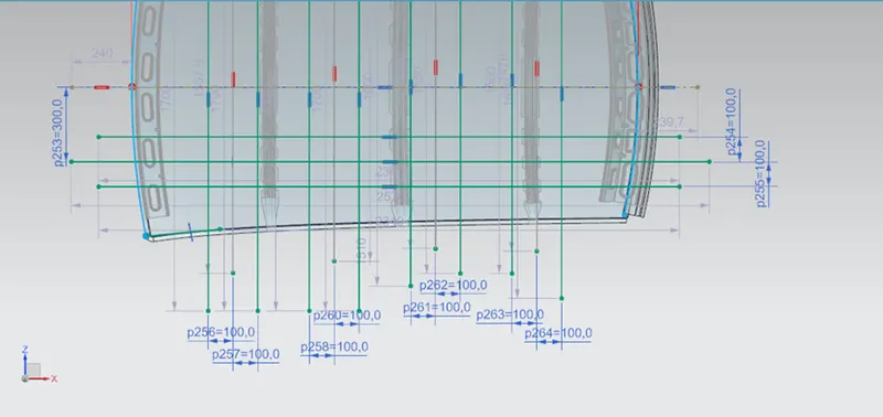
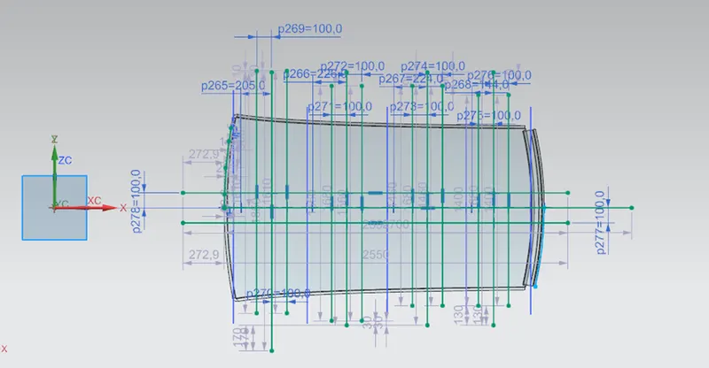
- From the 0-Y axis, at -3Y about a distance of 300mm is drawn parallel on the perpendicular plane as shown in the figure. Then after 100 mm lines are offset to either side of the -3Y line.
- Now centre lines are drawn between each adjacent roof rail edge respectively. Intersection points are marked on the sketch and exit the sketch. Make all geometry in construction lines except the points.
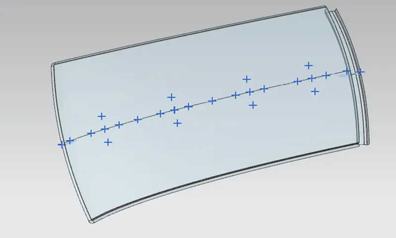
- Project the intersection points in the sketch to the roof surface as shown in the figure.
- Join the projected curves using
- an arc curve and measure the minimum radius and linear dimension of Rx and Ry.
Bow Roof Span (l):
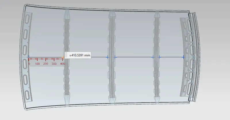
- Measured distance for Front roof rail to Bow roof rail 1. Measure similarly for others.
Calculation of W from above data:

- From above value chart, it is observed that W value is less than 2.7mm which is within criteria.
Conclusion:
- As per W value criteria it is proven that given design with assembly is perfect to sustain Heat Distortion Criteria.
Snow Load Criteria
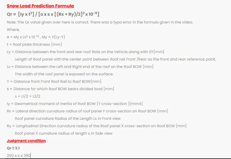
- Snow load criteria study is done to check the durability of the roof to withstand snowfall and reflex back to its original shape without any permanent deformation once the load is removed.
Model Calculation: -
- At the 0-Y axis on a perpendicular plane to the roof as shown in figure. Drawn 100 mm lines offset to either side of the 0Y axis line. Now centre lines are drawn between each adjacent roof rail edge respectively. Intersection points are marked on the sketch and exit the sketch. Make all geometry in construction lines except the points.
- Project the intersection points in the sketch to the roof surface as shown in figure.
- Join the projected curves using an arc curve and measure the minimum radius and linear dimension.
- Project the intersection plane bow roof and centre roof rail on the horizontal plane to find the moment of inertia of the respective section to find Iy values.
- Put all the linear and radial dimensions in the following formula to calculate Qr Value.
Section Modulus:
- Front Roof Rail
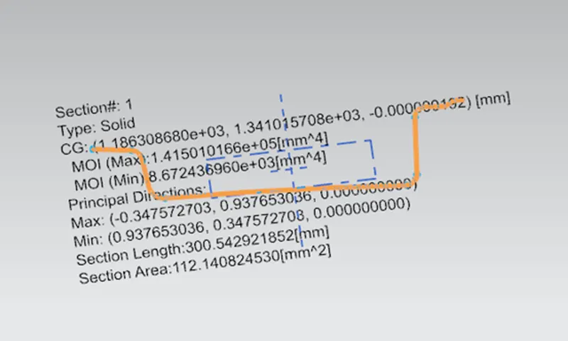
- Bow Roof Rail 1
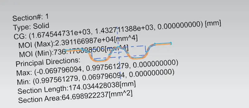
- Centre Bow Roof Rail
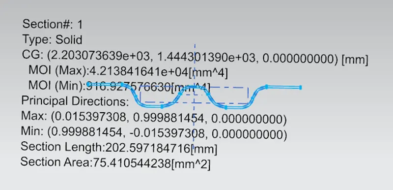
- Bow Roof Rail 2
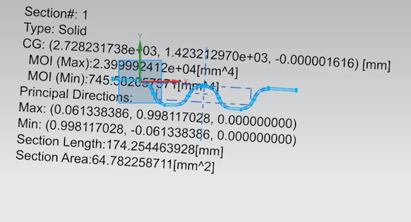
- Rear Roof Rail
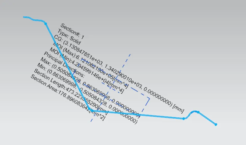
Calculation of Qr from data and formula:

- From above value chart, it is observed that Qr value is more than 3.1 which is within criteria.
Conclusion:
- As per Qr value criteria it is proven that given design with assembly is perfect to sustain Snow Load Criteria.