Roof Design
INTRODUCTION
An automobile roof is the portion of an automobile that its above the passenger compartment,protecting.The vehicle occupant from sun,wind,rain,and other external element.
In caseof roll over compartment integrity is provided by the compartment fromes whilst the roof target is only to avoid the ejection of passengers providing protection against hand lock contact.
Under the styling surface the is seen on the outside there are many other structures under the roof which strength and stability they are primarily installed on flatter area of the roof toenhance the strength.
FUNCTIONAL REQUIREMEN
- Type of roof and their functionality
- Roll over test regulation and requirement
- Identifiction methods to increase the strength of the roof.
- Material identification techniques
- joining techniques like mastic welding
- accessory part parpose and requirement [Roof rack and roof molding]
OBJECTIVE
For the given car roof styling design and develop the essential flanges and reinforcement namely the ditch area,front roof rail, rear roof rail,center roof rail and bow roof.
Do acurvature study on the roof and perform calcaulation for heat distartion and snow load criterion to determine and justify the postion of the bow roof
Do a section modulus study for the master section created for the front roof rail, rear roof rail,center roof rail and bow roof.
Perform draf analysis of each reinforcment.
Roof Design
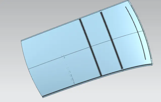
Draft Analysis of Roof and Roof Rails
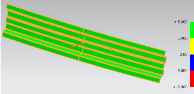
Draft analysis is carried out to obtain visual feedback on back draft condition of the part and an optimum die press direction is defined that maximises back draft. This analysis helps us to avoid die-lock situations, make decisions on an appropriate parting line, obtain suggestions on cutter sizing for machining and other purposes.
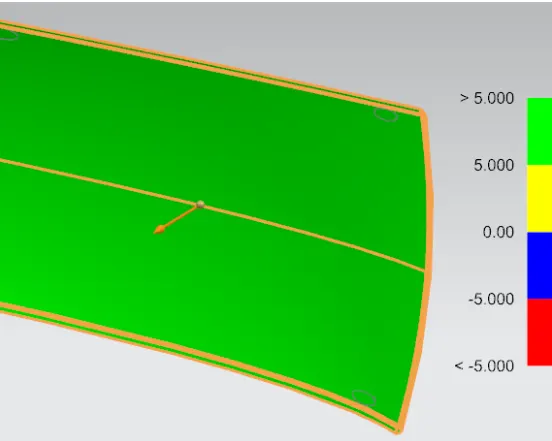
Draft Analysis of Front Roof Rail
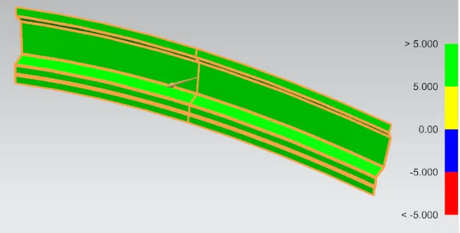
Draft Analysis of Center Roof Rail
roof prediction Formula
Formula w=1.73x10^-3xL+1.85x10^-8xR^2/t+1.10x10^-3x1-2.68
Where
L=Roof length in x-direction[mm]roof dimension
R=Roof curvatiue = 2(Rx*Ry)/(Rx+Ry)
RX=Xcurvature
RY=Ycurvature
t=Roof plate thickness[mm]
I=Bow roof spon[mm]
Judgement Condition : 2.7<W<3.5
| S.NO | BOWS | RX | RY | R | I | L | t | (R^2)/t | W | OK/NOTOK |
| 1 | FRR&BR1 | 5557.13 | 2031.3 | 3875.56 | 288.2 | 2034.23 | 0.65 | 2,31,07,042.71 | 1.57 | OK |
| 2 | BR&CRR | 4778.45 | 5583.76 | 5149.78 | 273.52 | 2034.23 | 0.65 | 4,07,99,726.25 | 1.99 | OK |
| 3 | CRR&BR2 | 3869.79 | 9550.7 | 5128.58 | 283.15 | 2034.23 | 0.65 | 4,66,71,910.92 | 1.99 | OK |
SNOWED CRITERIA
Prediction formula
Qr=lyxt^2/Sx[(Rx+Ry)/2]^2x10^8
Ly = Distance between front and rear roof rails[mm]
Lx = Distance between left and right end roof rails[mm]
Y = Distance between centre of front roof rail to centre of bow roof rail [mm]
S = Distance for which roof bow bears divided load [mm]
Iy = Geometrical moment of inertia of roof Bow (Y cross section) [mm4]Rx = Lateral direction curvature radius of roof panel Y cross section on roof bow
Ry = Longitudinal direction curvature radius of roof panel X cross section on roof bow
t = Roof plate thickness [mm]
| S.NO | BOES | iy | & | Lx | Ly | Y | My | & | Rx | Ry | t | Qr | DETERMINATION(Qr) |
| 1 | FRR&BR1 | 19145.8 | 0.88 | 1143.64 | 1901.78 | 476.79 | 679412.6 | 483.98 | 2817.70 | 1402.40 | 0.67 | 426.60 | OK |
| 2 | BR1&CRR | 20621.3 | 0.81 | 1093.87 | 1901.78 | 471.60 | 674463.4 | 494.9 | 3151.24 | 4405.04 | 0.67 | 152.30 | OK |
| 3 | CRR&BR2 | 23093.5 | 0.78 | 1067.65 | 1901.78 | 473.08 | 675879.82 | 640.58 | 3636.88 | 8496.97 | 0.67 | - | - |
| 4 | BR2&RRR | - | 0.76 | 1052.53 | 1901.78 | 476.46 | 679098.49 | - | 2961.80 | 13473.9 | 0.67 | - |
- |
From the above results it can be seen that the designed roof passes Snowed Criteria