Roof Design
ROOF DESIGN
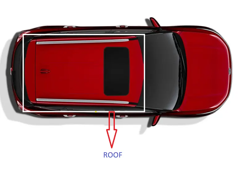
OBJECTIVES
- 1. For the given Car Roof styling, design and develop the essential flanges and reinforcements, namely the Ditch Area, Front Roof Rail, Rear Roof Rail, Centre Roof Rail and Bow-Roofs.
- 2. Do a curvature study on the roof and perform calculations for Heat Distortion and Snow load criterion to determine and justify the position of the Bow-roofs.
- 3. Do a Section Modulus study for the Master sections created for the Front Roof Rail, Rear Roof Rail, Bow Roof Rails and Centre Roof Rail
- 4. Perform Draft Analysis of each reinforcement.
SOFTWARE USED
CATIA V5
INTRODUCTION
- An automobile roof is the portion of an automobile that sits above the passenger compartment, protecting the vehicle occupants from sun, wind, rain, and other external elements.
- Under the styling surface that is seen on the outside, there are many other structures under the roof which contribute to its strength and stability. The number of such structures/supports differ with respect to the size of the vehicle.
- They are primarily installed on flatter areas of the roof to enhance the strength. These are the Front Roof Rail, Rear Roof Rail, Centre Roof Rail and Bow Roofs and they are joined to the roof by the Ditch Area.
REINFORCEMENTS
1.Ditch Area
- The Ditch Area is the extended portion of the main Roof concealed by other BiW panels.
- The rail supports of the roof are attached to the Ditch Area using Spot welds, since it is not a styling surface and remains concealed.
- Headroom Clearance, visibility criteria, clearance for Wind shield and Back door are some of the factors to be considered while designing the Ditch Area. It is given a thickness of 0.75 mm.
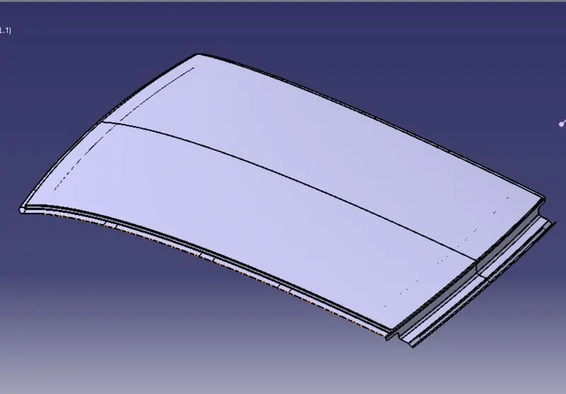
Car roof with Ditch Area and Railings. Embosses have been provided on the roof for better strength
2.Front Roof Rail
- It is the support which is joined with the Wind Shield Glass, Body Side Outer and the inner panels. It is usually made from Body Side Outer scrap and therefore the thickness of the rail is 0.75 mm.
- A draft angle of 7 degrees is provided keeping in mind the deep drawing operation. The Wind Shield end flange is the exact offset of the roof surface. The bottommost flange is decided after taking into consideration the visibility criteria and the Headroom Clearance of the passenger.
- Spot Welds are applied at Wind Shield end of the rail and the other end is joined with the roof using Mastic Sealants which also contributes to increased strength.
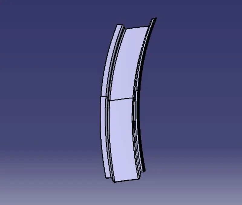
3.Rear Roof Rail
- It is the support which is joined to the Back Door and the Body Side Outer and the inner panels. It is also usually made from Body Side Outer scrap and therefore the thickness of the rail is 0.75 mm. Similar to the Front Roof Rail design, we have to take into consideration the rear Headroom Clearance and the rear visibility criteria while designing the Rear Roof Rail.
- Inputs from the backdoor design is also taken to accommodate the required clearance. Spot Welds are applied at the Back doorend of the rail and the other end is joined with the roof using Mastic Sealants.
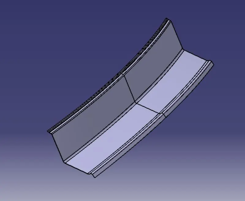
4.Centre Roof Rail and Bow Roofs
- Similar to other Rails design, we have to take into consideration the Headroom Clearance and the visibility criteria while designing the Centre Roof Rail and Bow Roofs. But unlike the Front and Rear Roof Rails, Spot Welds are not applied for joining these rails to the roof.
- Instead Mastic sealants are introduced at both the ends since Centre Roof Rail and Bow Roofs are fully positioned under the Styling surface of the Roof. For increasing the strength of the rails, embossing is done. To reduce the weight of the material used, a different styling has been followed with a thickness of 0.75 mm.
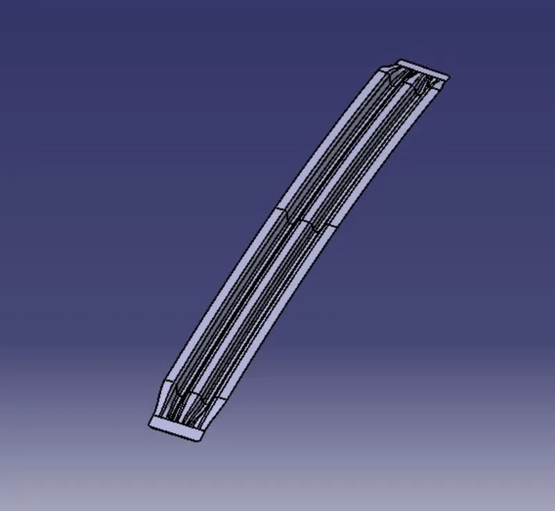
CENTER ROOF RAIL
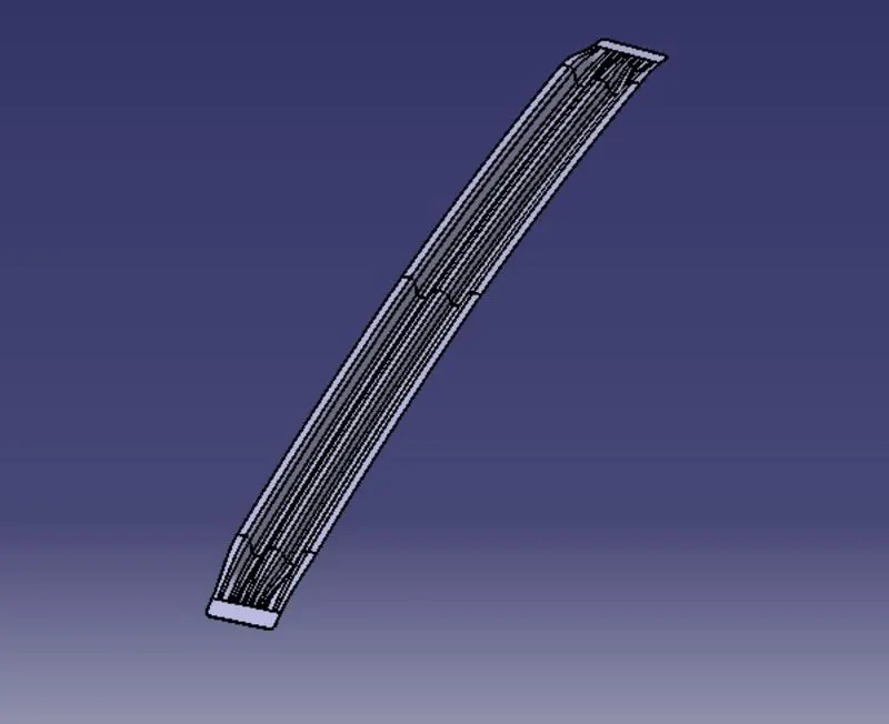
BOW ROOF 1
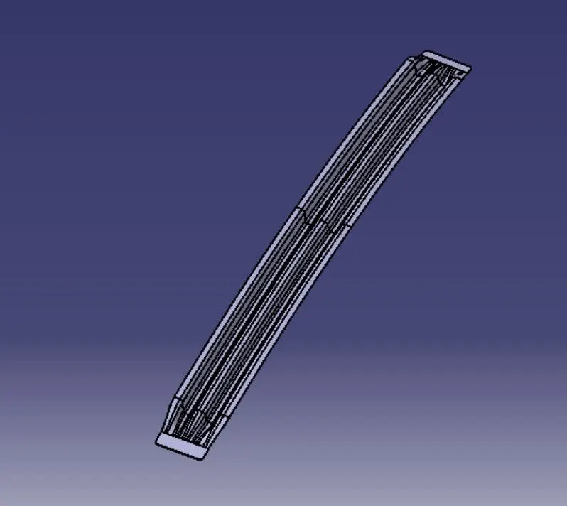
BOW ROOF 2
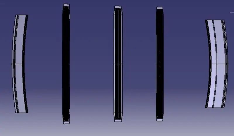
ROOF RAIL ASSEMBLY
DESIGN CONSIDERATIONS FOR A ROOF :
- Visibility criteria
- Head clearance
- Curvature study
- Heat distortion and snow load criteria
- Draft analysis
ANALYSIS
1. Curvature Study
It is done to justify the positioning of the Bow Roofs. There are mainly three criterion to fulfill
1. Roof Crush test
2. Heat Distortion Criteria
3. Snow Load Criteria
Roof Crush Testing is done only after the part or prototype is manufactured in physical conditions.
a. Heat Distortion Criteria
Heat distortion temperature is the temperature at which the metal softens and deforms under a specific load. This study is done to check the ability of the roof to withstand high temperature with respect to the positioning of the reinforcements which contribute to increased strength.
Prediction Formula :
W = [1.73 x 10^(-3) x L] + [1.85 x 10^(-8) x (R^2)/t] + [ 1.10x10^(-3) x l] - 2.68
Judgement Condition: OK < 2.7mm ≤ NG
Where,
L = Roof Length in X-Direction [mm] (Roof dimension in 0-Y)
R = Roof curvature= 2(Rx*Ry) / (Rx+Ry)
Rx = X curvature
Ry = Y curvature
t = Roof plate thickness (mm)
l = Bow Roof Span (mm)
When applying the corresponding measurements into the formula, the criterion is met for all the reinforcements.
| CASE | L | RX | RY | R | l | T | W |
| FRR - BR1 | 2032.743 | 3074.458 | 2468.454 | 2738.3289 | 375.267 | 0.75 | 1.434401 |
| BR1 - CRR | 2032.743 | 4982.948 | 4207.11 | 4562.2803 | 434.629 | 0.75 | 1.828159 |
| CRR - BR2 | 2032.743 | 4065.421 | 5755.7 | 4765.1065 | 332.435 | 0.75 | 1.762411 |
| BR2 - RRR | 2032.743 | 3347.767 | 6872.196 | 4502.2689 | 451.909 | 0.75 | 1.833749 |
Table 1- Heat Distortion criterion calculation
b. Snow Load Criteria
Snow load criteria study is done to check the ability of the roof to withstand snowfall and bounce back to its original shape without any permanent deformation once the load is removed.
Prediction Formula: Qr = [Iy x t2] / [α x s x [(Rx + Ry)/2]2 x 10-8]
Judgment condition: Qr ≥ 3.1
Where,
α=My×Lx2×10−12,My=Y(Ly−Y)
t = Roof plate thickness (mm)
Ly = Distance between front and rear roof rails on vehicle 0-Y (mm) i.e. Length of Roof panel with the centre point between Roof rail FR/RR as the reference point of the front/rear.
Lx = Distance between the left and right end of roof on the roof BOW (mm) i.e. Width of the Roof panel exposed on surface
Y = Distance from Front roof rail centre to Bow roof (mm)
s = Distance for which Bow roof bears divided load (mm) = L1/L2 + L2/2
Iy = Geometrical moment of inertia of Bow roof (Y cross section) (mm4)
Rx = Lateral direction curvature radius of roof panel Y cross section on Bow roof (mm) i.e. Roof panel curvature radius of the length Lx in front view
Ry = Longitudinal direction of curvature radius of roof panel X cross section on Bow roof (mm) i.e. Roof panel X curvature radius of the length s in side view
When applying the corresponding measurements into the formula, the criterion is met for all the reinforcements.
| CASE | ly | a | s | RX | RY | MY | LX | LY | L1 | L2 | Y | T | QR |
| FRR - BR1 | 23280 | 0.9168516 | 491.1805 | 2702.986 | 2533.793 | 704698.6 | 1140.638 | 1968.617 | 470.339 | 512.022 | 470.339 | 0.75 | 9.41796E-17 |
| BR1 - CRR | 27800 | 1.1482017 | 460.956 | 3761.967 | 3175.522 | 968859.4 | 1088.626 | 1968.617 | 512.022 | 409.89 | 982.361 | 0.75 | 4.63946E-17 |
| CRR - BR2 | 23440 | 0.9048432 | 493.1275 | 4229.976 | 4086.182 | 802446.1 | 1061.888 | 1968.617 | 409.89 | 576.365 | 1392.251 | 0.75 | 3.83027E-17 |
Table 2- Snow Load criterion calculation
2. Section Modulus Study
Section modulus is a geometric property for a given cross-section used in the design of beams or flexural members. There are two types of section moduli, the Elastic Section Modulus and the Plastic Section Modulus. For general design, the Elastic Section Modulus is used, applying up to the Yield Point for most metals and other common materials.
Section modulus is calculated using the formula
S=I/y
Where,
S = Section Modulus
I = Moment of Inertia
Y = distance between the neutral axis and the extreme end of the object
Front Roof Rail
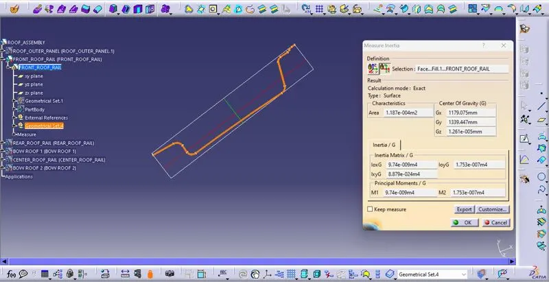
I = 9.74e-009 m4 = 97400 mm4
Y = 128.1 mm
S = 760.3 mm3
Rear Roof Rail
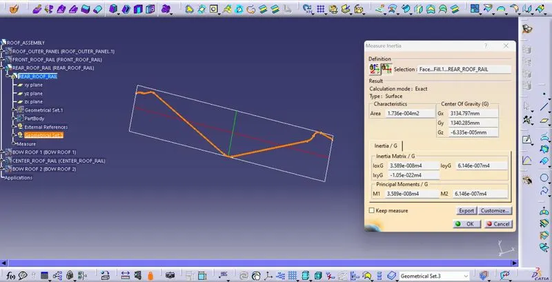
I = 3.589e-008m4 = 35890 mm4
Y = 205.5 mm
S = 174.6 mm3
Centre Roof Rail
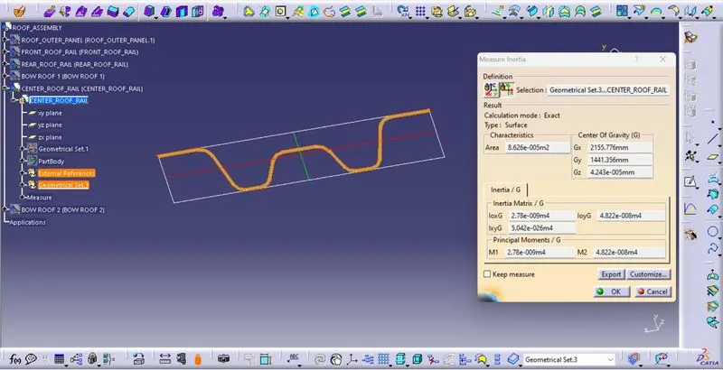
I = 2.78e-009 m4 = 27800 mm4
Y = 85 mm
S = 327.0 mm3
Bow Roof 1
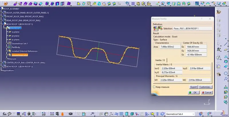
I = 2.328e-009 m4 = 23280 mm4
Y = 70.01 mm
S = 332.5 mm3
Bow Roof 2
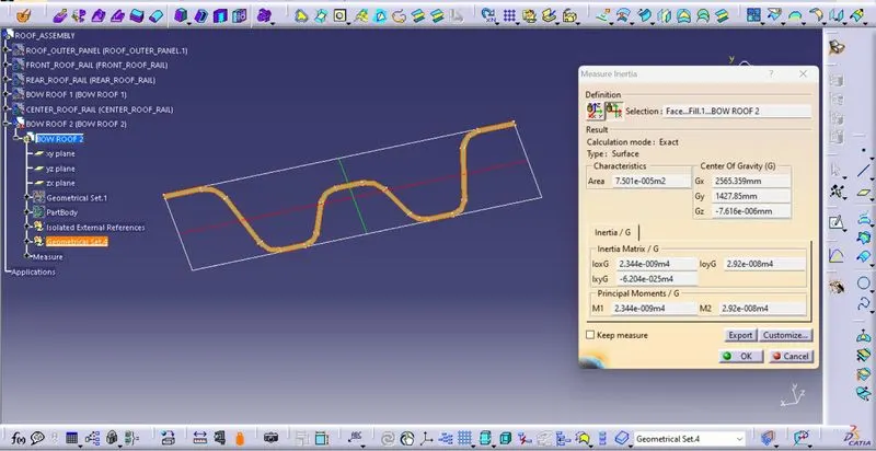
I = 2.344e-009 m4 = 23440 mm4
Y = 70 mm
S = 334.8 mm3
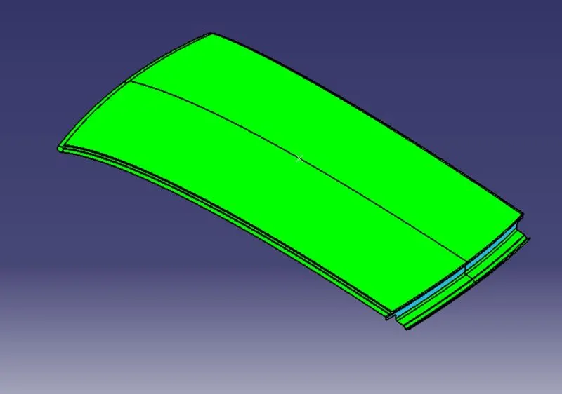
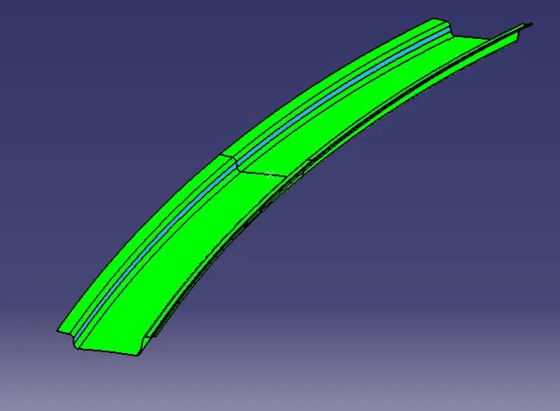
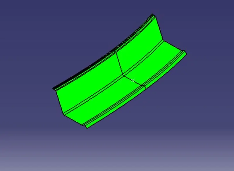
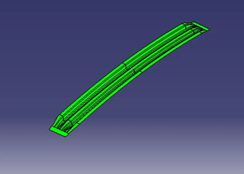
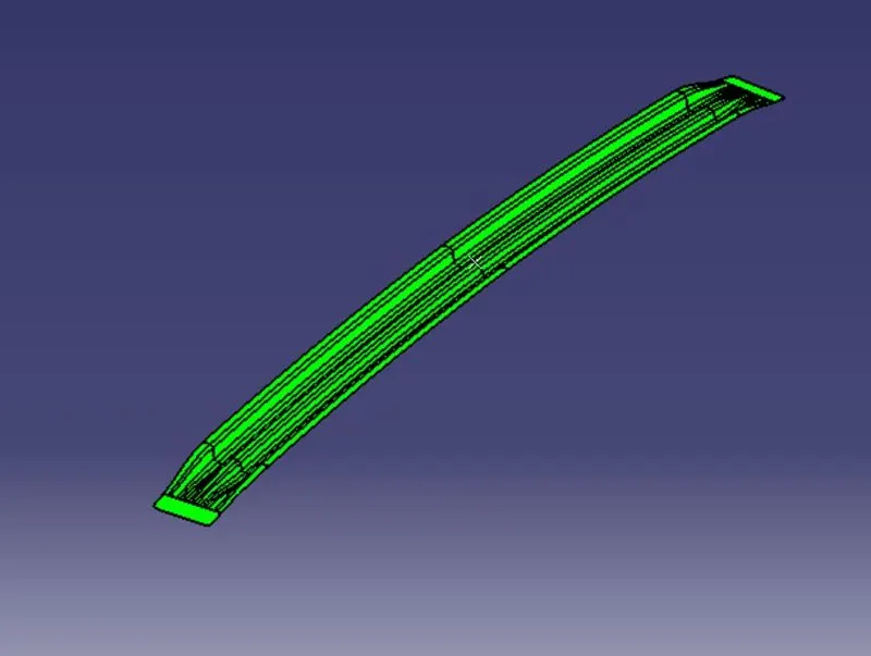
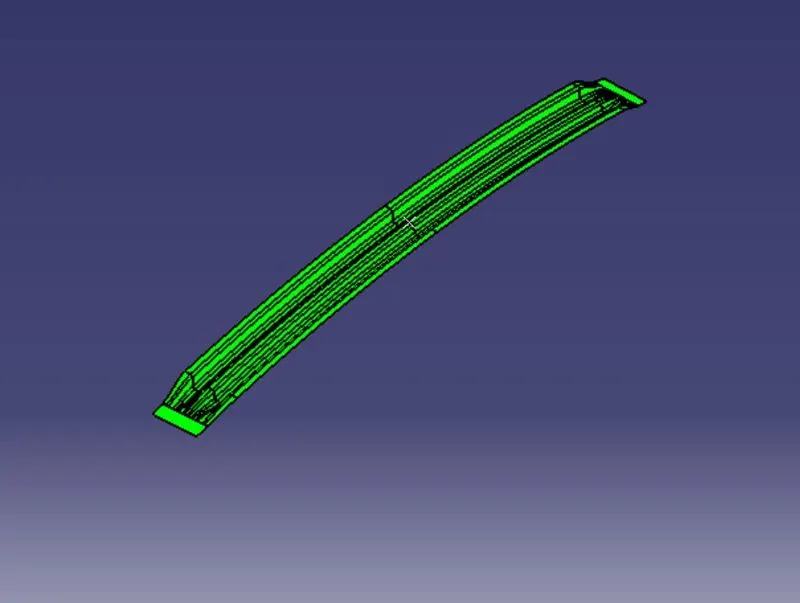
3. Draft Analysis
- Draft Analysis is done to analyze the draft angle. This allows us to verify whether the product will be easily removed from the tool.
- When designing a product they need to be angled slightly so that the tool can be pulled away from the object easily, without deformation or damage. This slight angle is called draft.
Ditch Area
Front Roof Rail
Rear Roof Rail
Centre Roof Rail
Bow Roof 1
Bow Roof 2
Conclusion
- Thus the required reinforcements and Ditch Area for the Roof were designed and developed from the given styling.
- The curvature study was done after performing calculations for the Heat Distortion and Snow load conditions with the position criterion met for all reinforcements.
- Further the Section Modulus study was conducted and Draft Analysis were done for each reinforcement succesfully.