Roof Design
Aim:
Create an assembly by developing the essential flanges for the outer roof and creating the reinforcements for the given roof styiling. Also check the draft analysis and do a curvature study on the roof and perform calculations to determine the position of the Bow-roofs.
Introduction:
An automobile roof or car top is the portion of an automobile that sits above the passenger compartment, protecting the vehicle occupants from sun, wind, rain, and other external elements.
Roof is connected to A pillar, B pillar and C pillar. Thus the roof is supported by reinforcement with front and rear roof rails.
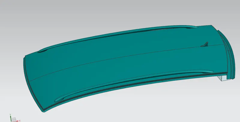
Car Roof:
An automobile roof is the portion of an automobile that sits above the passenger compartment, protecting the vehicle occupants from sun, wind, rain, and other external elements. The roof is the structure above the windshield glass having the reinforcements to provide strength to the overall structure and to withstand overhead forces like snow.
Reinforcement:
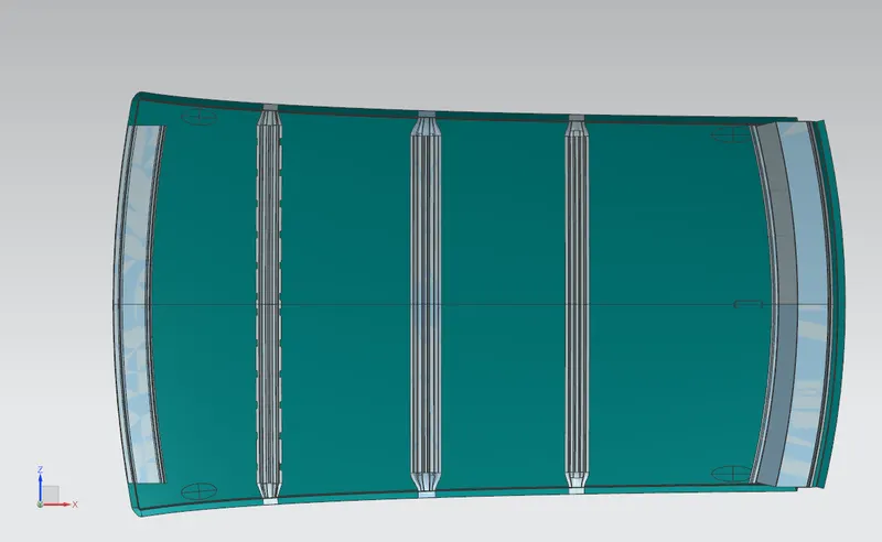
If the roof is flat, it is very weak and is not able to withstand the forces like snow, so to increase the strength of the roof these reinforcements like front roof rail, central roof rail, rear roof rail, and bow roof rail are introduced and joined to the flat surface of the roof with the different joining process.
Types of Reinforcement:
- Front Roof Rail
- Bow Roofs
- Central roof rail
- Rear Roof Rail
Front Roof Rail:
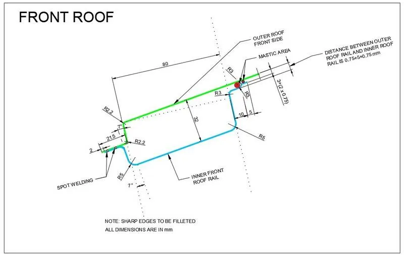
The front roof rail is a join between windshield glass, body side outer, and inner panel. It is designed as per the gievn master section.
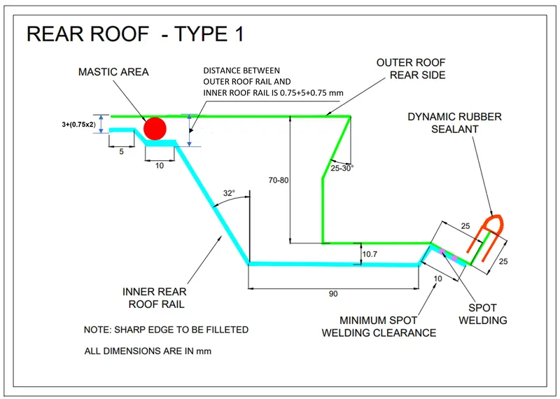
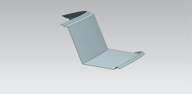
Rear Roof Rail:
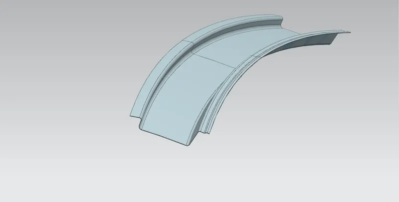
The rear Roof Rail is a join between the back door and the body side outer. Designed according to the given master section.
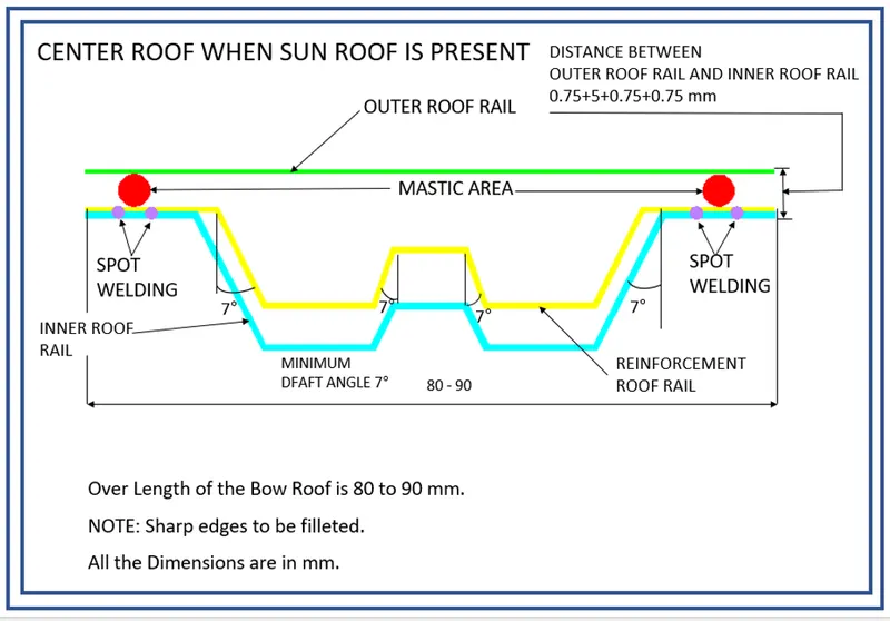
Central Roof Rail:
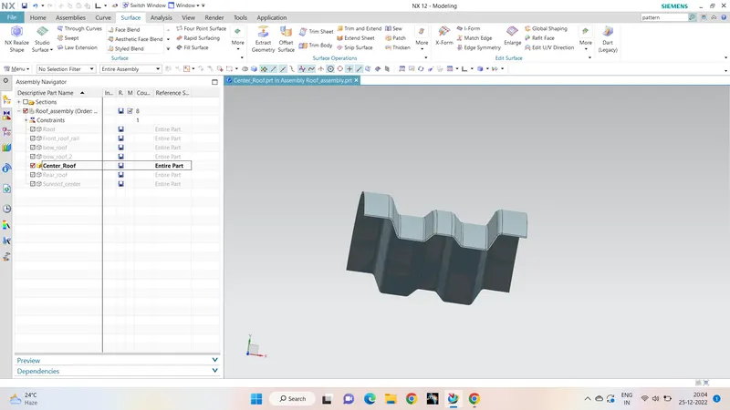
The central roof rail helps in providing effective support to the flat area of the roof as it is more susceptible to failure under the action of load, generally central roof rail is placed at the center of the roof which is connected to the B-pillar support structure. This helps in adding strength to the roof during the roll-over test.
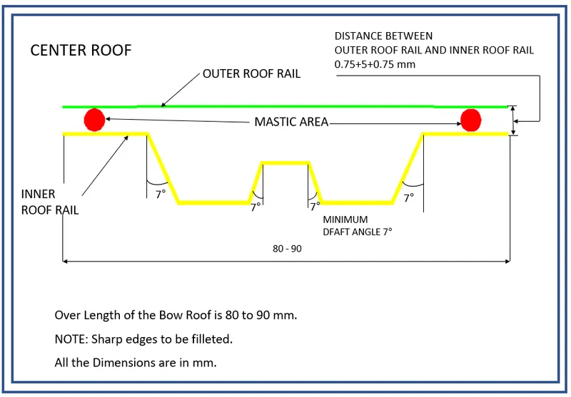
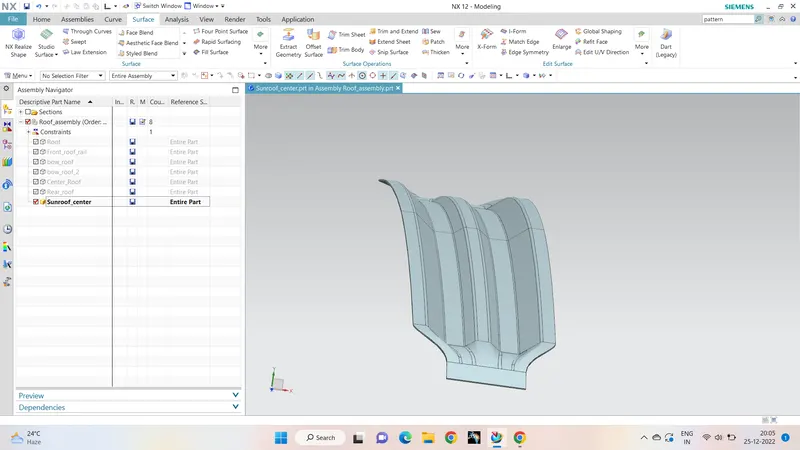
Center Roof Rail When sunroof is present:
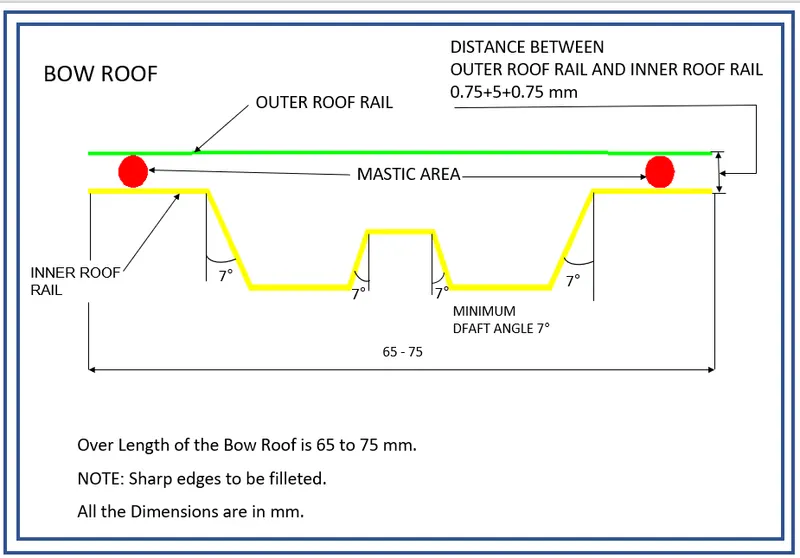
Bow Roofs:
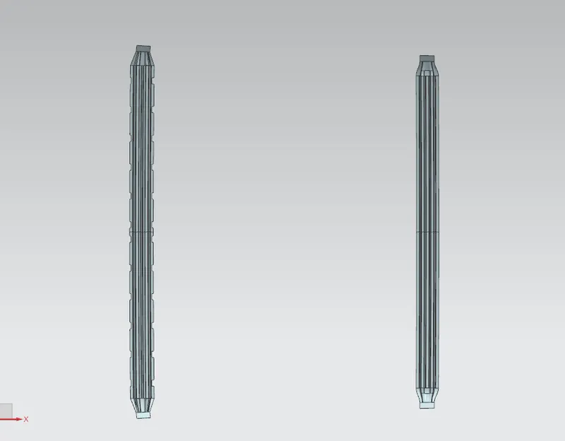
The Bow roofs are given to improve the torsional stiffness and load-bearing capacity of the roof structure. The number of bow roofs presents depends on the overall size of the roof.Presently, in this project, only two bow roofs have been provided.
Joining process:
Mastic is introduced between the roof outer panel and the reinforcement for joining. Where ever the mastic is introduced there is a remarkable strength increase.
Spot welding is also introduced to join the reinforcements and outer panel.Spot Sealer creates a rustproof, waterproof and dustproof seal that protects spot‐welded metal parts.
Design Considerations For a Roof:
- Visibility criteria
- Head Clearance
- Curvature study
- Heat distortion and snow load criteria
- Draft Analysis
Roof Crush Test:
The roof crush test is the design given by the IIHS (Insurance Institute of Highway Safety). After analyzing many accidents IIHS has then fixed some regulations in performing crash tests.
IIHS gives the rating based on this test. For this, they consider two points while giving the rating.
- How fast the car can reform to its original shape after the rollover and
- How deep is the protrusion after the rollover?

The Goal Of The Roof Crush Test:
To minimize the protrusion into the occupant compartment, so that seat belts and airbags can do their job protecting the occupant
Conditions To Follow For Roof Crush Test:
Two conditions should be followed for the roof crush test, they are :
Intial Condition:
- Close and lock all the doors
- Close all the windows
Second Condition :
Fix the body sill or chassis frame on a hard lever surface horizontally.
Method of Applying the Force :
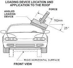
The load is applied in such a way that 5 degrees is tilted from the front end to the rear end and the load will be 1800 mm in length and 750 mm in width. The load is applied at the position of 25 degrees from the flatness of the roof. The load is applied on the roof for almost 120 sec and the crushing speed at which the load is applied is 13 mm/sec or less than that.
Results :
If the displacement goes above the required level then we have to increase the bow roof thickness or add more mastic points to increase the strength. The stronger the roof the better it can protect the occupants in roll-over crashes.
Heat Distortion Study on The Roof:
The heat distortion study plays a major role in sheet metal urges. Heat distortion temperature is a temperature limit above which the material cannot be used for structural applications. This study is used to predict the heat distortions temperature at where the material starts to soften when exposed to a fixed load at an elevated temperature. To avoid bending or damage to the roof, based on the heat distortion temperature, this study will predict the bow roof position which helps to strengthen the roof.
Bow–Roof Prediction Formula
W = [1.73 x 10^(-3) x L] + [1.85 x 10^(-8) x (R^2)/t] + [ 1.10x10^(-3) x l] - 2.68
Where,
L = Roof Length in X-Direction[mm](Roof dimension in 0-Y)
R = Roof curvature
R = 2(Rx*Ry)/(Rx+Ry)
Rx = X curvature
Ry = Y curvature
t = Roof plate thickness [mm]
l = Bow Roof Span [mm]
Judgment Condition
OK< 2.7
Calculations:

According to the table mentioned above, the roof is in safer zone as the W values are below 2.7 as per the standard condition.
Thus the design passes the Heat Distorsion Test.
Snow Load Criteria:
This test is done to know-how is the roof is behaving when there is snow over. Normally due to the snow weight, the dent will happen. But the roof should be designed in such a way that when the snow is removed the roof should go to its original position. These are basic requirements for the snow load criteria.

Snow Load Prediction Formula
Qr = [Iy x t2] / [α x s x [(Rx + Ry)/2]2 x 10-8]
Where,
α = My x Lx2 x 10-12 , My = Y(Ly-Y)
t = Roof plate thickness [mm]
Ly = Distance between the front and rear roof Rails on the Vehicle along with 0Y[mm]
Length of Roof panel with the center point between Roof rail Front /Rear as the front and rear reference point.
Lx = Distance between the Left and Right end of the roof on the Roof BOW [mm]
The width of the roof panel is exposed on the surface.
Y = Distance front Front Roof Rail to Roof BOW[mm]
s = Distance for which Roof BOW bears divided load [mm]
s = L1/2 + L2/2
Iy = Geometrical moment of inertia of Roof BOW (Y cross-section )[mm4]
Rx = Lateral direction curvature radius of roof panel Y cross-section on Roof BOW [mm]
Roof panel curvature Radius of the Length Lx in Front view
Ry = Longitudinal Direction curvature radius of the Roof panel X cross-section on Roof BOW [mm]
Roof panel X curvature radius of length s in Side view
Judgment condition
Qr ≥ 3.1
250 ≤ s ≤ 380

According to the calculations from the above table, the S value is greater than the desired value. The alternatives for its correction are:
- The surface provided can be sent to the styling team and ask to increase the emboss in the particular areas to strengthen the roof.
- The designed bow roofs thickness can be increased.
- The distance b/w the roof rails can be adjusted accordingly to satisfy the s value.
Since the Qr value has satisfied,the designed elements are'nt disturbed.
Therefore the roof passes one of the standard criteria Qr>3.1.
Section Modulus :
Section modulus is a geometric property for a given cross-section used in the design of beams or flexural members. Other geometric properties used in the design include an area for tension and shear, the radius of gyration for compression, and the moment of inertia and polar moment of inertia for stiffness. Any relationship between these properties is highly dependent on the shape in question. Equations for the section moduli of common shapes are given below.
The elastic section modulus is defined as S = I/y
Where,
S = Section modulus
I = Moment of inertia
y = distance between the neutral axis and the end of the object
It is also often used to determine the yield moment (M y) such that
M y = S X σ y
Where
σ y = yield strength of the material
M y = yield moment
Ʃ y for stainless steel is 520MPA
Calculation of the section modulus :
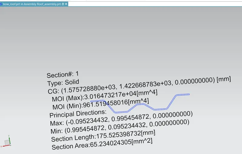
Bow roof-1:
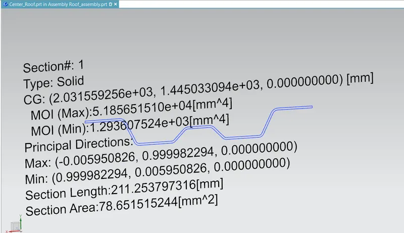
Center Roof:
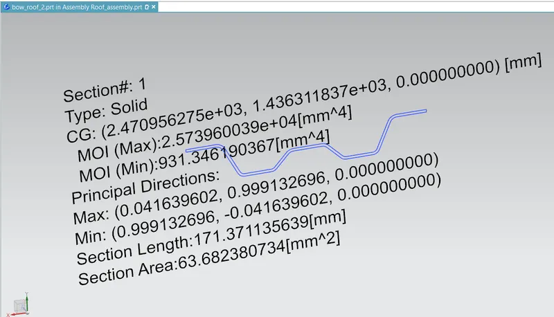
Bow Roof-2:
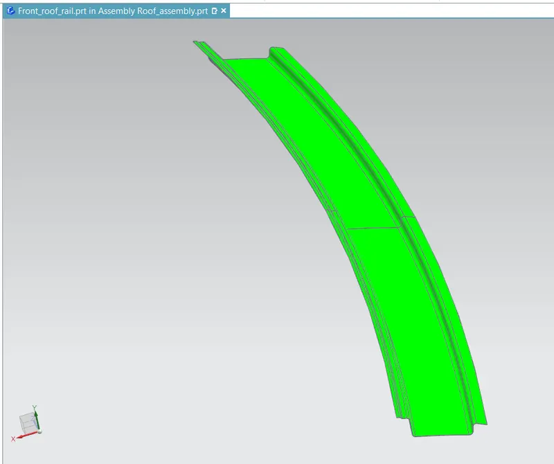
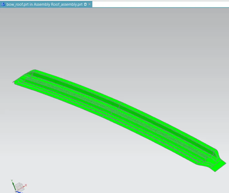
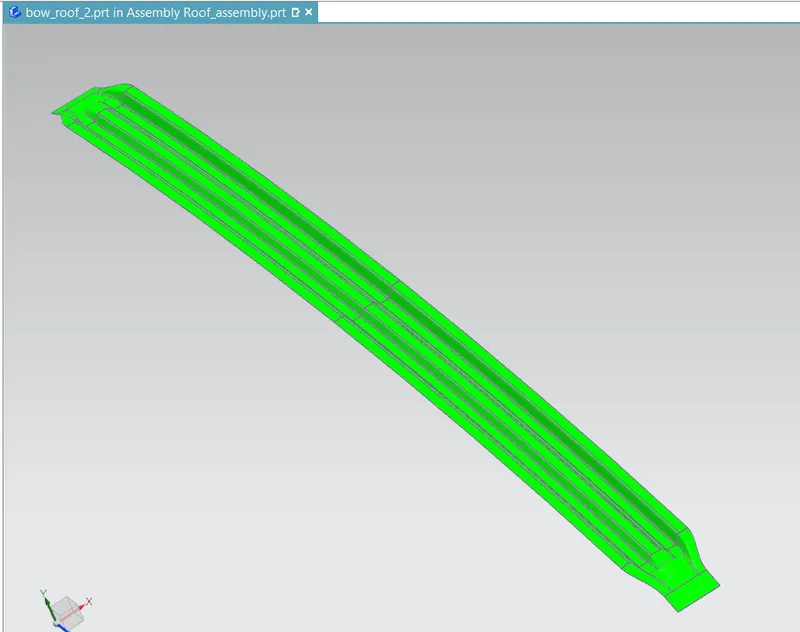
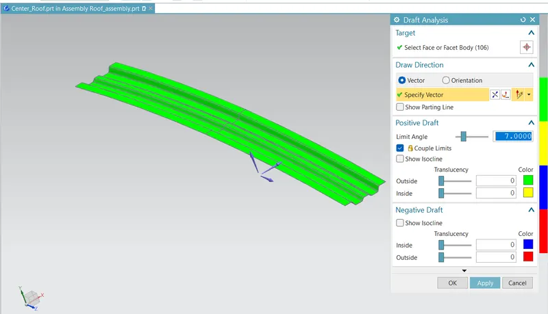
Draft Analysis :
The Draft analysis command enables you to detect if the part you drafted will be easily removed. This type of analysis is performed based on color ranges identifying zones on the analyzed element where the deviation from the draft direction at any point, corresponds to specified values.
Draft Analysis For Front Roof Rail:
Draft Analysis For Bow Roof 1:
Draft Analysis For Bow Roof 2:
Draft Analysis For Center Roof Rail:
Draft Analysis For Center Roof reinforcement:
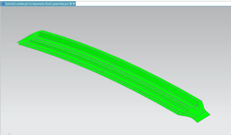
Draft Analysis For Rear Roof Rail:
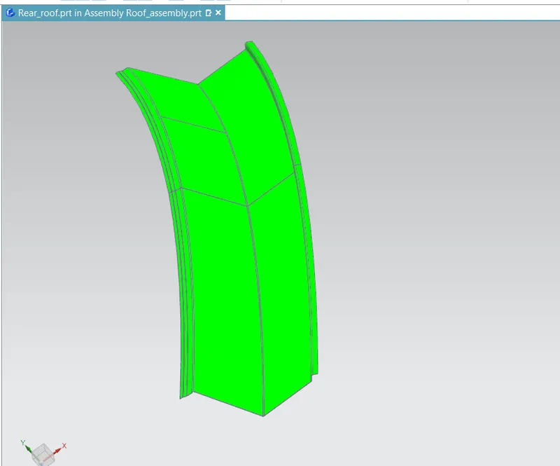
Draft Analysis For Roof Rail:
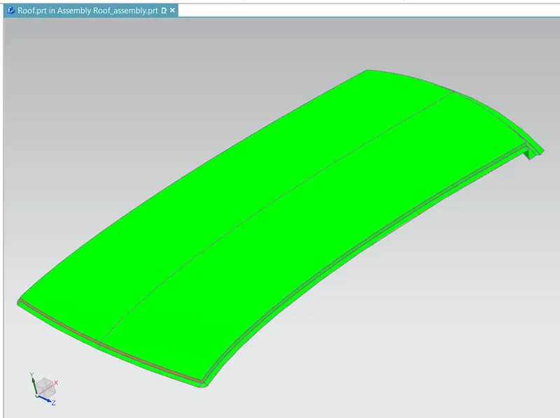
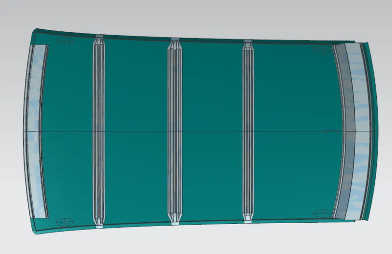
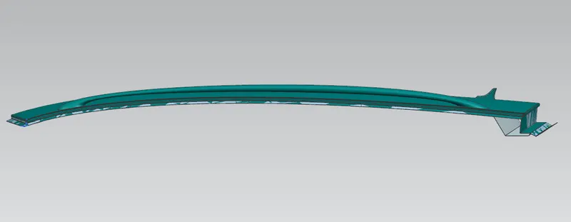
Roof Images:
Top View:
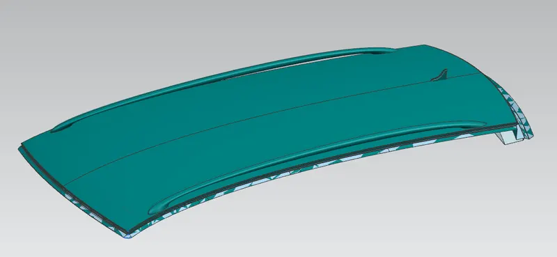
Bottom View:
Side View:
Conclusion:
The aim is achieved by designing the required roof rails according to the design considerations and its calculations for heat distortion and snow load criterias along with draft analysis for the roof rails.
Design is ready with all the required design elements and is carried out for manufacturability.
The zip file of the design and excel sheet of the calculations are been submitted below.
Thank You.