Roof Design
OBJECTIVE :
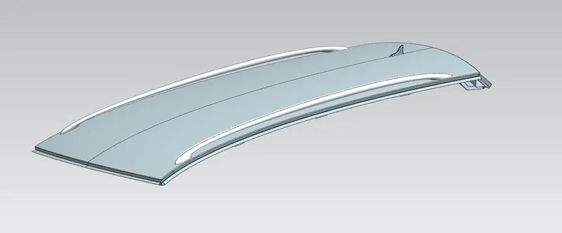
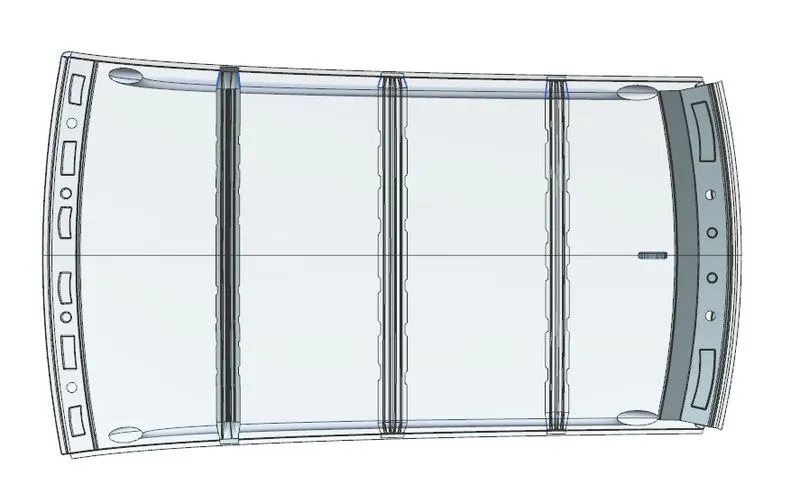
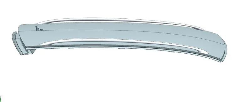
- The objective of this project is to design car roof with essential flanges and reinforcements like ditch area , front roof rail , bow roofs, central roof rail and rear roof rail for the the given styling surface
- Perform a curvature study on the roof and perform the calculations for the heat distortion and snow load criteria to determine whether the bow roofs are at the correct positions.
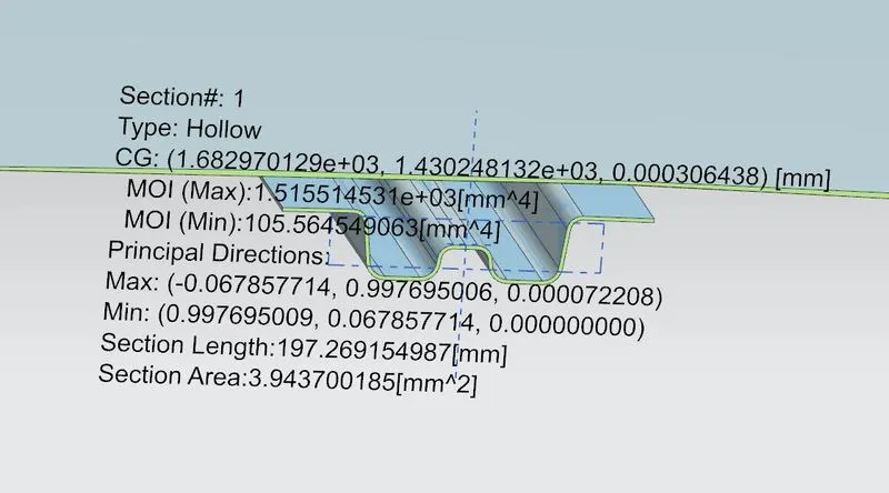
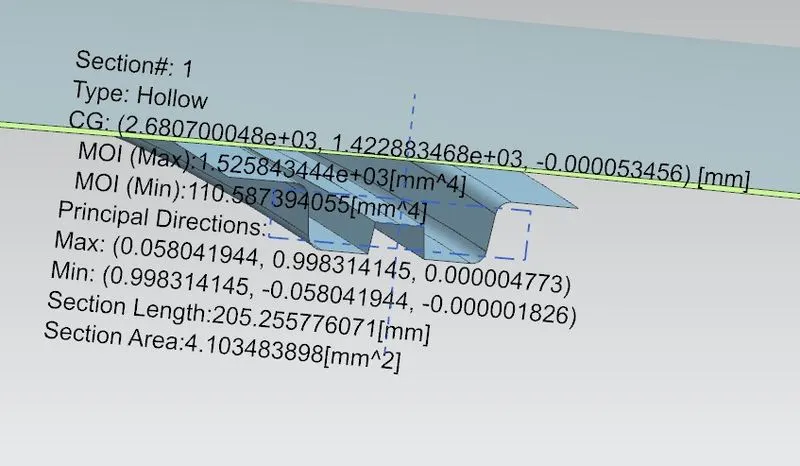
- Finding moment of inertia and section modulus for Bow roofs , central roof rail . front roof rail and rear roof rail .
- Perform the draft analysis for each reinforcements.
BOW ROOF :
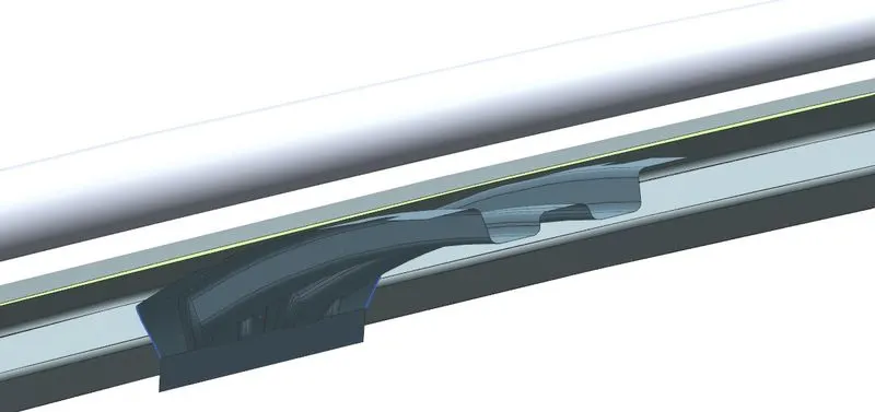
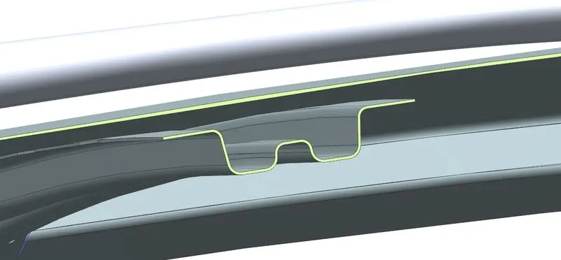
The bow roofs are given to the improve the torsional stiffness and load bearing capacity of the roof structure. When number of bow roofs are given by the roof dimension. Longer the roof area we have to give the more bow roof to the structure.
Bow–Roof Prediction Formula
W = [1.73 x 10^(-3) x L] + [1.85 x 10^(-8) x (R^2)/t] + [ 1.10x10^(-3) x l] - 2.68
Where,
L = Roof Length in X-Direction[mm](Roof dimension in 0-Y)
R = Roof curvature
R = 2(Rx*Ry)/(Rx+Ry)
Rx = X curvature
Ry = Y curvature
t = Roof plate thickness [mm]
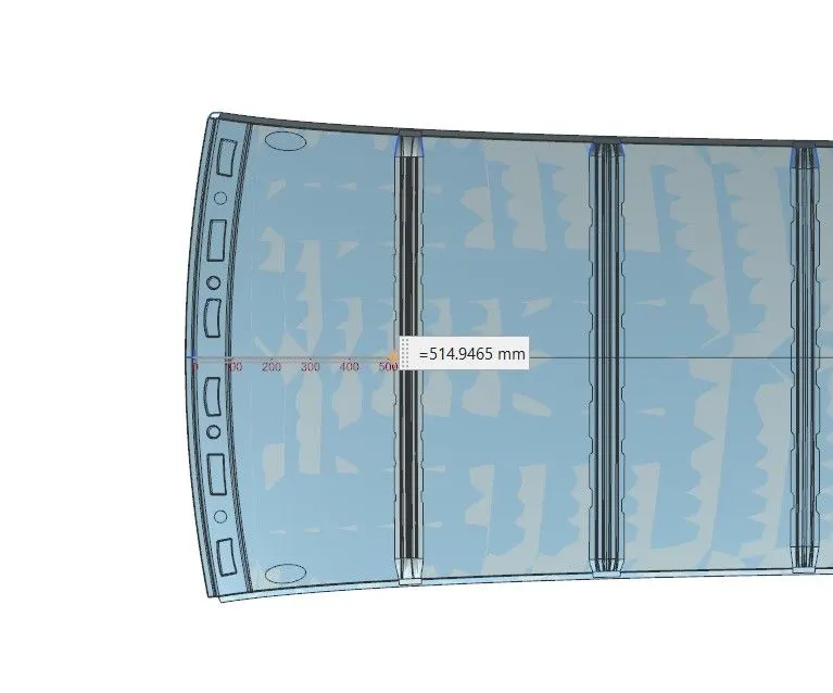
l = Bow Roof Span [mm]
ROOF LENGTH(L): 2039.5099 mm
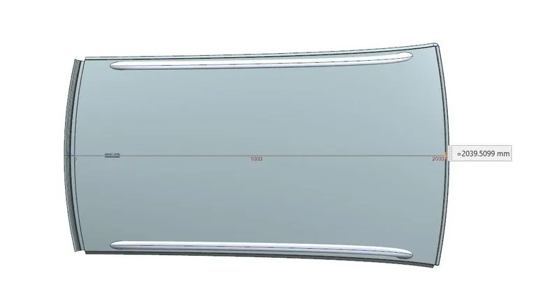
t = 0.75mm
BOW ROOF SPAN (l) = 514.946mm
Distance from front roof rail to bow roof front.
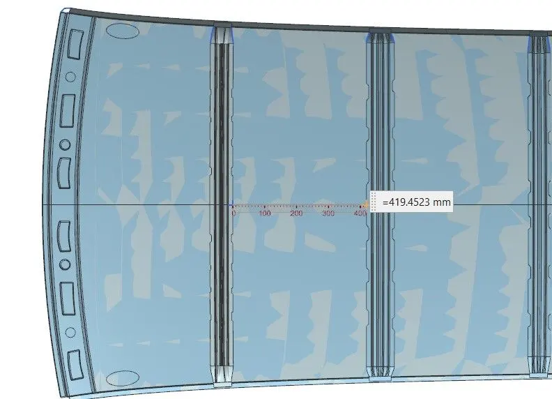
Distance from Front bow -Centre Bow Roof:
Distance from Centre bow roof -Back Bow Roof:
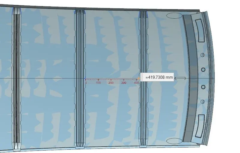
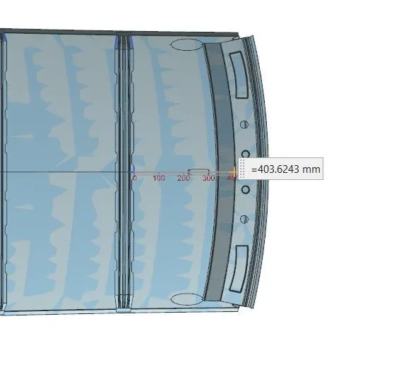
Distance from Back bow roof – Rear rail:
RX:
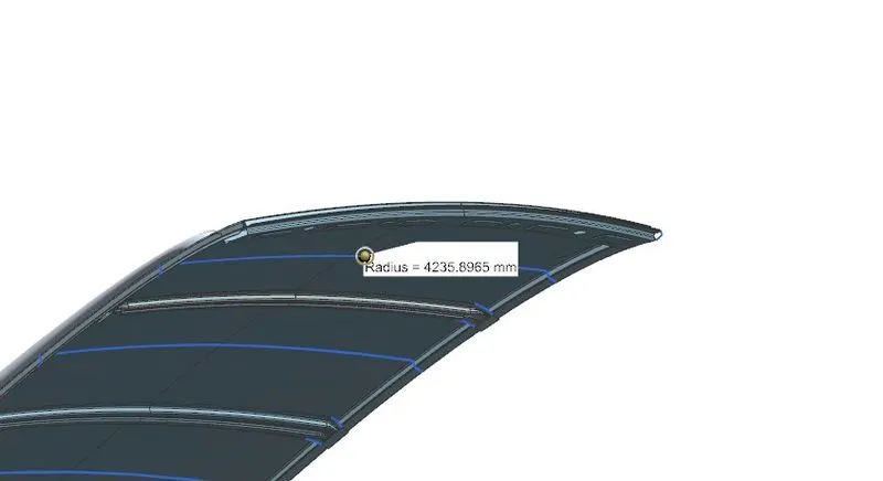
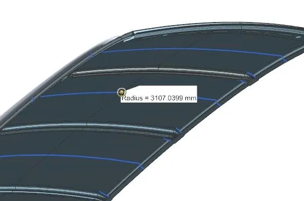
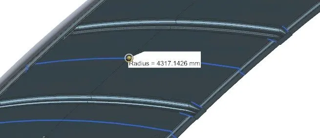
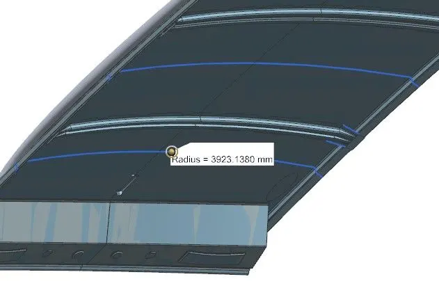
Ry:
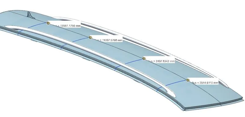
|
Descriptioin |
Rx |
Ry |
Rx*Ry |
R*x+R*y |
R |
L |
t |
I |
W |
Results |
|
Front rail -Front Bow Roof |
4236 |
2915 |
12345991 |
7150.51 |
3453.1788 |
2039.5 |
0.75 |
514.9 |
1.7089296 |
OK |
|
Front bow -Centre Bow Roof |
3107 |
3108 |
9656164.9 |
6214.87 |
3107.437 |
2039.5 |
0.75 |
419.5 |
1.5479351 |
OK |
|
Centre bow roof -Back Bow Roof |
4317 |
11098 |
47909822 |
15414.7 |
6216.1134 |
2039.5 |
0.75 |
419.7 |
2.2631767 |
OK |
|
Back bow roof – Rear rail |
3923 |
15587 |
61150642 |
19510.3 |
6268.5452 |
2039.5 |
0.75 |
403.6 |
2.2616071 |
OK |
SNOW LOAD CRITERIA :
This test is done to know how is the roof behaving when there is a snow over . normally due to the snow weight the dent will happen. But the roof should be designed in such a way that when the snow is removal the roof should go it its original position .
Qr = [Iy x t2] / [α x s x [(Rx + Ry)/2]2 x 10-8]
Where
α = My x Lx2 x 10-12 , My = Y(Ly-Y)
Judgement condition = Qr ≥ 3.1
250 ≤ s ≤ 380
t = Roof plate thickness [mm]
Ly = Distance between the front and rear roof Rails on the Vehicle along with 0Y[mm]
Length of Roof panel with the center point between Roof rail Front /Rear as the reference point of the front and the rear.
Lx = Distance between the Left and Right end of the roof on the Roof BOW [mm]
Width of the roof panel exposed on the surface.
Y = Distance front Front Roof Rail to Roof BOW[mm]
s = Distance for which Roof BOW bears divided load [mm]
s = L1/2 + L2/2
Iy = Geometrical moment of inertia of Roof BOW (Y cross-section )[mm4]
Rx = Lateral direction curvature radius of roof panel Y cross-section on Roof BOW [mm]
Roof panel curvature Radius of the Length Lx in Front view
Ry = Longitudinal Direction curvature radius of the Roof panel X cross-section on Roof BOW [mm]
|
RAIL |
ly |
LX |
LY2 |
L1 |
L2 |
RX |
RY |
Y |
S |
RX+RY/2 |
My |
α |
Qr |
|
FR-BW1 |
1515 |
1082 |
2039.51 |
514.947 |
419.452 |
4235.9 |
2914.6 |
514.947 |
467.19925 |
5642628 |
785069.1432 |
0.919099288 |
35.17136 |
|
BW1-CRBW |
2794 |
1103 |
2039.51 |
419.452 |
419.73 |
3107 |
3107.8 |
996.28 |
419.59115 |
4209309 |
1039349.184 |
1.264481572 |
70.37191 |
|
CRBW-BW2 |
1525 |
1142 |
2039.51 |
419.73 |
403.62 |
4317.1 |
11098 |
1500 |
411.675 |
8459787 |
809265 |
1.055414279 |
23.33756 |
It is observed from the values that obtained values of QR > 3.1
Section analysis:
Section moment of inertia is used to predict the amount of deformation and deflection of a part. A higher moment of inertia is preferable as it reduces the amount of deflection for a given force.
DRAFT ANALYSIS:
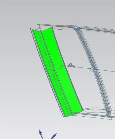
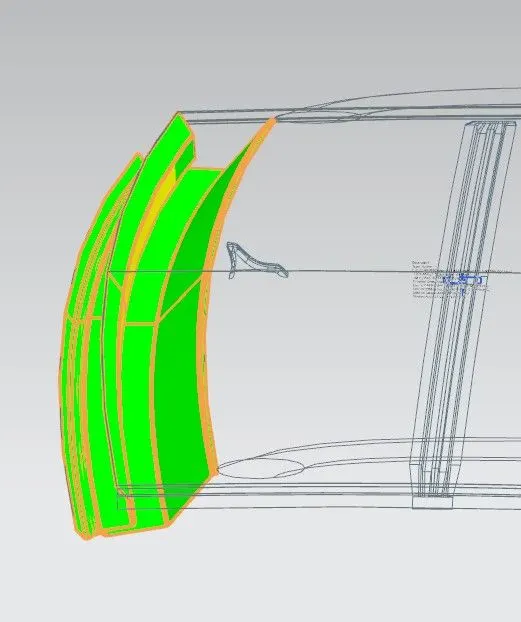
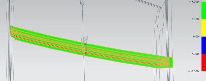
The Draft Analysis command enables you to detect if the part you drafted will be easily removed. This type of analysis is performed based on color ranges identifying zones on the analyzed element where the deviation from the draft direction at any point, corresponds to specified values.
Minimum draft angle of 70 is considered for analysis .