Roof Design
DESIGNING OF ROOF USING NX-CAD
INTRODUCTION
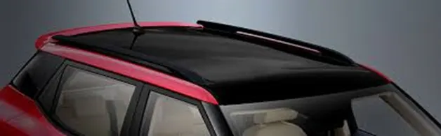
An automobile roof is the portion of an automobile that sits above the passenger compartment, protecting the vehicle occupants from sun, wind, rain, and other external elements. Though it just looks like a styling surface that protects from sun, wind and other elements, various environmental conditions are taken into account for designing of the same. Roof should be provided with the proper reinforcements for strengthening. Vehicle roof can be subjected to high heat conditions or load during snowy conditions. To make the roof withstand these conditions, various calculations are done. This ensures the safety of the passengers in the vehicle.
OBJECTIVE
- The objective of this project to design car roof with essential flanges and reinforcements like ditch area, front roof rail, bow rails, central roof rail and rear roof rail for the given styling surface.
- Perform a curvature study on the roof and perform the calculations for the heat distortion and snow load criteria to determine whether the bow roofs are the correct positions.
- Finding moment of inertia and section modulus for front roof rail, bow rails, central roof rail, and rear roof rail.
- Perform the draft analysis for each reinforcement.
- Visibility criteria and head clearance consideration.
PURPOSE OF REINFORCEMENT
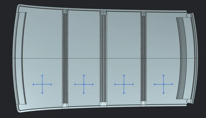
If the roof is flat, it is very weak and cannot able to with stand the forces like snow, so in order to increase the strength of the roof, these reinforcements like front roof rail, central roof rail, rear roof rail and the bow roofs are introduced and joined to the flat surface of the roof with the different joining process.
COMPONENTS
- Front roof rail
- Central roof rail
- Rear roof rail
- Bow roofs
DESIGN CONSIDERATIONS
- Clearance of 5mm should be present between outer roof rail and front roof rail, rear roof rail, bow roof rail, and reinforcement centre where mastics are used for adhesion.
- Thickness for all sheet metal parts should be 0.75mm.
- A minimum draft of 7 degrees should be maintained for all faces.
- All edges should have fillets and there should be no sharp corners.
DITCH AREA
The ditch area is the extended portion of the main roof which is concealed by the other BIW components followed by the other aesthetic surface. It also serves the joining purpose for the reinforcement which is joined using the spot welding. Visibility clearance for windshield and back door mountings are some of the factors needed to be considered while designing the ditch area.
FRONT ROOF RAIL
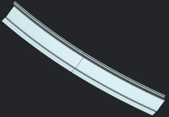
The front roof rail is used as the reinforcement to the roof surface and joined to the BIW body and windshield. Visibility criteria is taken in account for joining it with windshield. It is fixed to BIW with spot welding and roof surface is attached with help of mastic sealants.
Front roof rail is used as the reinforcement to the roof surface to increase the strength and also used to mount the brackets for some features such as room lamp or map lamp and rear mirror.
The width of the front roof rail is decided in such way that there should be enough headroom clearance between the head of the driver and the end surface of the roof rail to avoid injuries to the person.
The depth of the front roof rail is decided based on the visibility criteria line decided for the driver visibility.
CENTRAL ROOF RAIL
Central roof rail helps in providing effectively support to the flat area of the roof as it is more susceptible to failure under the action of load. Generally central roof rail is placed at the centre of the roof which is connected to the B-pillar support structure. This central roof rail helps in adding the strength to the roof during the roll-over test. It is fixed to roof by mastic sealants and to BIW body by spot welds. The cross-section of this more since it needs to provide strength to roof.

REAR ROOF RAIL
Rear roof rail is the one which joins the back door and the body side outer. It is the reinforcement provided at rear side of the roof. Inputs from the backdoor are taken into consideration for designing this roof rail. Joining method using mastic sealants and spot welding.
BOW ROOF RAILS
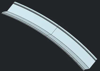
Bow roof is an additional stiffening member for the roof to increase the torsional stiffness and load bearing capacity of roof structure and so that it can satisfy the norms. Both the ends are joined together using mastic sealants to increase strength and also since this would not affect the styling of the roof. The number of bow roof present is depending on the overall size of the roof. The cross-section of the bow is made in such a way that we should get the maximum value of the minimum moment of inertia at which the bow fails.

CURVATURE STUDY
The curvature study analysis helps us to determine and validate the positioning of the bow roof rails. The curvature study of roof is done through two main criteria’s:
- Heat distortion criteria
- Snow load criteria
HEAT DISTORTION CRITERIA
It is an important factor to determine the position of the roof. It plays a major role in sheet metal usage. Heat distortion temperature is a temperature limit above which the material cannot be used for the structural applications. This study is used to predict the heat distortion temperature at where the material starts to soften when exposed to a fixed load at elevated temperature. In order to avoid bending or damages on the roof , based on the heat distortion temperature, this study will predict the bow roof position which helps to strengthen the roof.
Bow-roof prediction formula
W = [1.73 x 10^(-3) x L] + [1.85 x 10^(-8) x (R^2)/t] + [1.10 x 10^(-3) x l] – 2.68
Where,
L- length in X – direction in mm
Rx- value of X curvature
Ry- value of Y curvature
R- roof curvature – 2*(Rx*Ry) / (Rx+Ry)
t- thickness of the component
l- bow roof span
|
HEAT DISTORTION CRITERIA |
||||||||
|
SECTION |
NAME |
L |
Rx |
Ry |
t |
l |
W |
REMARKS |
|
section 1 |
Front roof rail - Bow roof rail 1 |
1924 |
1565.6 |
5679.2 |
0.75 |
451.5 |
1.29 |
ok |
|
section 2 |
Bow roof rail 1 - Centre roof rail |
1924 |
2434.8 |
4577.9 |
0.75 |
359 |
1.29 |
ok |
|
section 3 |
Centre roof rail - Bow roof rail 2 |
1924 |
3399.2 |
3656.9 |
0.75 |
382.4 |
1.37 |
ok |
|
section 4 |
Bow roof rail 2 - Rear roof rail |
1924 |
3727.2 |
3206.1 |
0.75 |
384.4 |
1.36 |
ok |
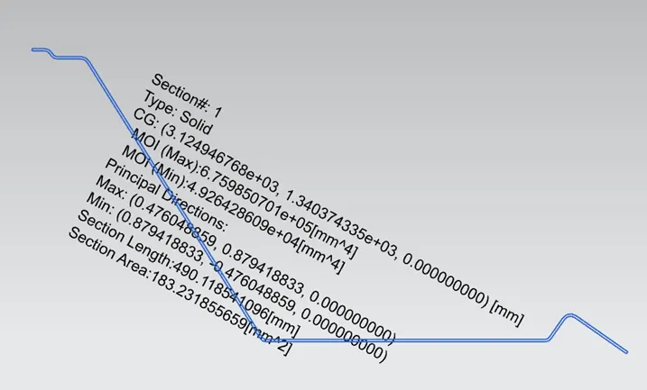
AREA MOMENT OF INERTIA
The area moment of the inertia of a beams cross sectional area measures the beam ability to resist bending. The larger the moment of inertia, less will be the bend.
Where,
M = Bending moment
I = Area moment of inertia
E = young’s modulus
R = Radius of gyration
FRONT ROOF RAIL
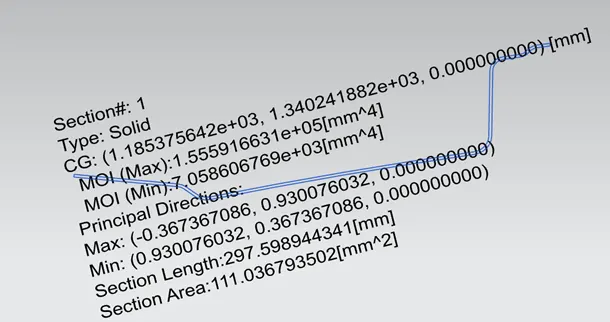
BOW ROOF RAIL 1
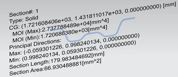
CENTRAL ROOF RAIL
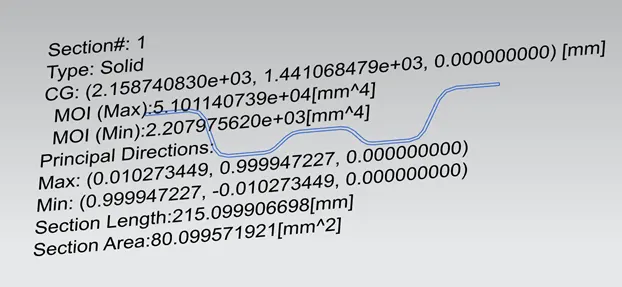
BOW ROOF RAIL 2
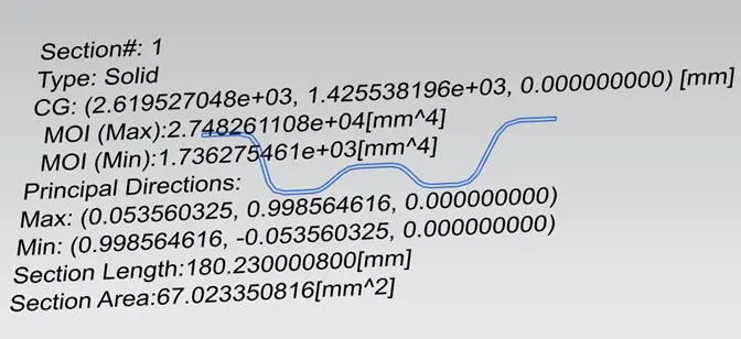
REAR ROOF RAIL
SNOW LOAD CRITERIA
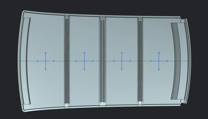
The roof an automobile must be able to withstand load especially snow which results in heavy load acting on the roof. If the roof is not able to withstand it, there will be deformation of the roof. To prevent that, snowed criteria calculation helps us to determine whether the roof design will withstand the snow load.
Qr = [ly x t^2] / [αx s x [(Rx + Ry)/2]^2 x 10^-8]
Where,
α= My x Lx^2 x 10^-12, My = Y(Ly-Y)
Judgement condition = QR>3.1
250< s < 380
t = roof plate thickness in mm
Ly =distance between the front and rear roof rails on the vehicle along with 0Y [mm]
Length of roof panel with the centre point between roof rail front/rear as the reference point of the front and the rear.
Lx = distance between the left and right end of the roof on the roof BOW [mm]
Width of the roof panel exposed on the surface
Y = distance from front roof rail to Roof BOW[mm]
s = distance for which roof BOW bears divided load [mm]
s = L1/2 + L2/2
ly = geometrical moment of inertia of roof BOW ( y cross-section) [mm^4]
Rx = lateral direction curvature radius of roof panel Y cross section on roof BOW [mm]
Roof panel curvature radius of the length Lx in front view
Ry = longitudinal direction curvature radius of the roof panel X cross section on roof Bow [mm]
|
SNOW LOAD CRITERIA |
|||||||||||
|
SECTION |
NAME |
Iy |
t |
α |
Rx |
Ry |
L1 |
L2 |
Y |
Qr |
REMARKS |
|
section 1 |
Front roof rail - Bow roof rail 1 |
1924 |
0.75 |
1.1 |
2779 |
4226.7 |
544.5 |
437.6 |
544.5 |
1.44 |
not ok |
|
section 2 |
Bow roof rail 1 - Centre roof rail |
1924 |
0.75 |
0.66 |
6399.2 |
3777.7 |
437.6 |
461 |
1640.8 |
1.55 |
not ok |
|
section 3 |
Centre roof rail - Bow roof rail 2 |
1924 |
0.75 |
0.99 |
10843.2 |
4105.1 |
461 |
512.6 |
1443.2 |
3.12 |
ok |
|
section 4 |
Bow roof rail 2 - Rear roof rail |
1924 |
0.75 |
_ |
16017 |
4063.4 |
512.6 |
0 |
_ |
_ |
_ |
DRAFT ANALYSIS
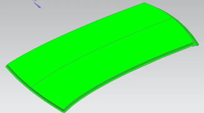
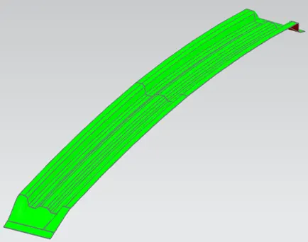
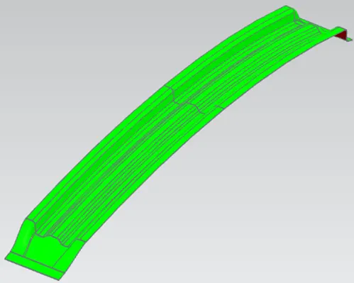
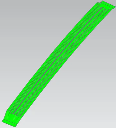
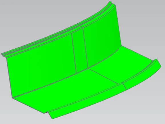
Draft analysis is done to check if the component does not have any negative draft. A negative draft can create a problem during the manufacturing process. Sheet metal parts must have a draft of atleast 7 degrees for proper tooling.
ROOF OUTER PANEL
FRONT ROOF RAIL
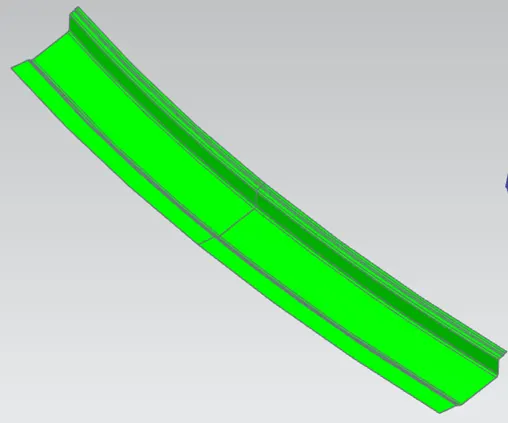
BOW ROOF RAIL 1
CENTRAL ROOF RAIL
BOW ROOF RAIL 2
REAR ROOF RAIL
MANUFACTURING TECHNIQUES
BLANKING It is the process where the required sheet metal material is cut from the sheet metal coil for the manufacturing of the hood using a blanking die. Blanking is a punching operation in which entire periphery is cut out and the cut-out portion required is known as STAMP OR BLANK.
- When a component is produced with one single punch and die where the entire outer profile is cut in a single stroke the tool is called a blanking tool.
- Blanking is the operation of cutting flat shapes from sheet metal.
- The outer area of metal remaining after a blanking operation is generally discarded as waste.
- Size of blank or product is the size of the die & clearance is given on punch.
- It is a metal cutting operation.
TRIMMING
When cups and shells are drawn from flat sheet metal the edge is left wavy and irregular, due to uneven flow of metal. Shown is flanged shell, as well as the trimmed ring removed from around the edge. While a small amount of Material is removed from the side of a component in trimming tool.
DEEP DRAWING
Deep drawing is one of the most widely used processes in sheet metal forming. Apart from its use in many other sectors, it is applied in the automotive industry for the manufacturing of car body parts. The deep drawing process is a forming process which occurs under a combination of tensile and compressive conditions.
Sheet metal blank is radially drawn into a forming die by the mechanical action of a punch. It is thus a shape transformation process with material retention. The process is considered "deep" drawing when the depth of the drawn part exceeds its diameter. This is achieved by redrawing the part through a series of dies. The flange region (sheet metal in the die shoulder area) experiences a radial drawing stress and a tangential compressive stress due to the material retention property. These compressive stresses (hoop stresses) result in flange wrinkles. Wrinkles can be prevented by using a blank holder, the function of which is to facilitate controlled material flow into the die radius.
EMBOSSING
Sheet metal embossing is the stamping process to obtained raised or sunken edges for the desired design pattern on the sheet metal. This is done with help of male and female dies between which sheet metal is placed and the dies are pressed against the sheet metal to obtain the designed pattern. In some cases, roller dies are used to get the raised edges in the sheet metal.
Manufacturing considerations for the emboss creation
- The distance between the outer edges of the emboss should be a minimum of 5mm
- Draft angle should be provided to the emboss with 7degree- 9degree for the easy removal of the part from the die
- No sharp corners to be provided in the emboss can it would lead to inefficient manufacturing
- The height of the emboss should not be more than 5mm
SPOT WELDING
Resistance Spot Welding (often just called spot welding) is a cost-effective joining technology that continues to be very popular in the automotive industry where high reproducibility and automation are essential criteria. An additional advantage is that, with a suitable choice of parameters, a high quality of joints can be obtained without being dependent on a welder’s ability.
Resistance Spot Welding is a pressure welding process. The sheets are pressed together locally with the help of fitted copper electrode welding guns that then have a current applied to them. As a result, Joule heating locally melts the joining partners at the junction resulting in a cohesive composite once the joint has solidified.
MASTIC SEALANTS
Mastic is a form of sealant or adhesive used to fill the joints or as a bond for different materials and gaps. It is an elastic and flexible material used to create a durable bond between two different surfaces or to protect a particular surface. We cannot use other joining techniques like welding, riveting etc because they leave marks on the roof outer panel which spoil its aesthetic appearance. So, mastic sealants are used to stick the inner surfaces of roof outer panel and rear and front end of front roof rail and rear roof rail respectively. Mastic sealants are elastic compound that behave like rubber. It is applied between at specified spots. Each spot of mastic sealants has its effect around a circular region of 80mm diameter.
CONCLUSION
The car roof design and its reinforcements were developed from the given stylish surface. A detailed report about the engineering standards for roof design, its analysis for tooling feasibility, heat distortion and snow load conditions as well as manufacturing techniques were prepared with necessary pictures and calculations. Understood requirement of reinforcements of roof and their positioning and joining method of front roof rail and rear roof rail.
THANK YOU…….