Roof Design
ROOF ASSEMBLY
OBJECTIVE:
Main objective of the project is to create the Roof Sheetmetal design in NX cad, and also designing front roof rail, rear roof rail, bow roof (front and rear), centre roof rail and needed reinforcement are creating to build the strong roof.
Do curvature study on Roof and performance calculations for Heat distortion and Snow load criteria to determine the position of the Bow roofs.
Finding the moment of inertia and section modulus for Bow-roofs and centre roof.
Finding the Draft Analysis of each part.
ROOF:
The roof is an essential part of a vehicle that plays an indispensable role in providing effective protection for you and those who drive with you from heavy snow, harsh rain, strong wind, harmful UV rays, etc. Like many other automotive body panels, the roof is subjected to environmental conditions. Hail and snowstorms may burst, tree limbs and branches may fall, etc. All this can damage the roof and cause sharp dents, dings, and scratches. Your vehicle can also become ruined in an accident. Though a defect may seem insignificant at first, it can lead to serious consequences. Whether your roof was dented due to downfall or roughed up in a collision, it is urgently necessary to find a replacement for IT. The roof panel is attached to the BIW of the car with the help of the front and rear roof rail. This attachment is done with the help of sealants. 1-2 bow roofs are attached depending upon the length of the roof along with the central roof rail. Longer the roof, more the number of the new roof rail. Other dimensions like strength and material are governed by factors like headroom, overall space, visibility, ergonomics, and the rules and regulation of the states where it is sold.
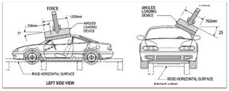
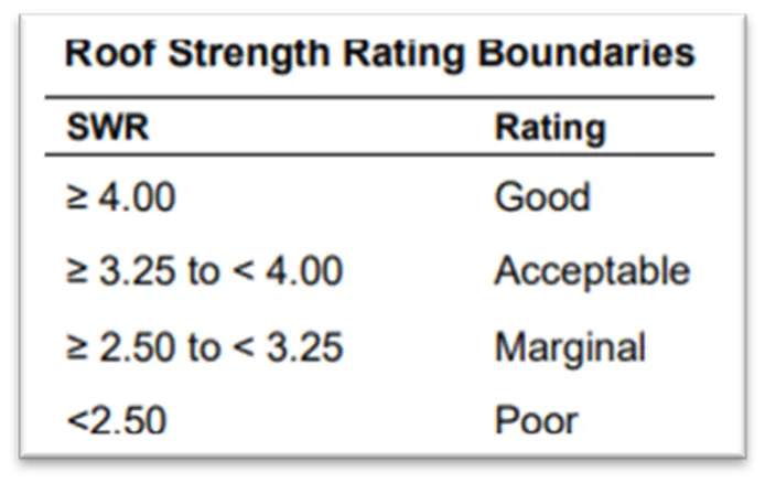
ROOF STRENGTH TESTING:
DESIGN CONSIDERATION OF THE ROOF:
- VISIBILITY CRETERIA
- HEAD ROOM CLEARANCE
- BOW ROOF POSISTION
- HEAT DESTORATION
- SNOW LOAD CRETERIA
- DRAFT ANALYSIS
MASTER SECTION:
Master section data for front roof rail, rear roof rail, bow roof front, bow roof rear, Canter roof rail and reinforcement. It is used for reference to draw the object.
FRONT ROOF RAIL:
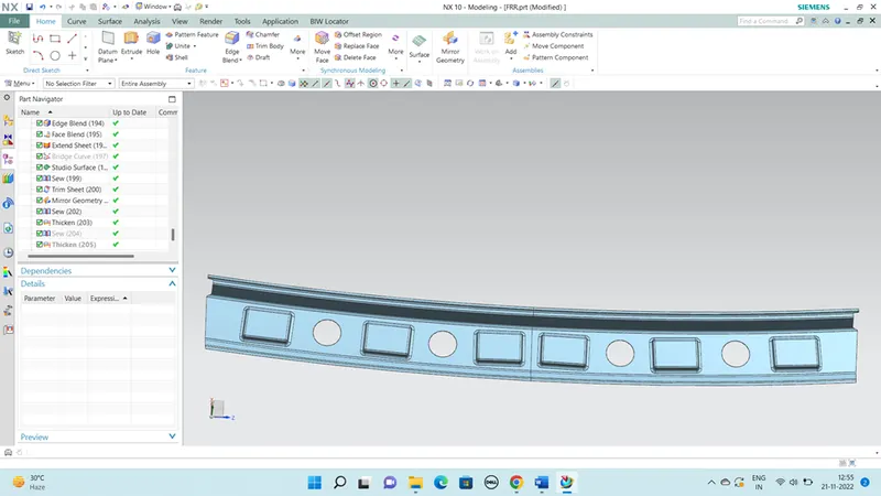
Front roof rail is used for supporting the roof for externally applied forces occurring at accidents. When we increasing the front roof rail is good for strength but also it is not for drivers because of it hide visibility of road. When considering the parameters of roof rail, give them 60-80mm length, proper draft angle and also using the embosses for increasing the strength. Front section of front roof rails spot welded to the front ditch area and other end is fixed with help of mastic sealants.
FRONT BOW ROOF:
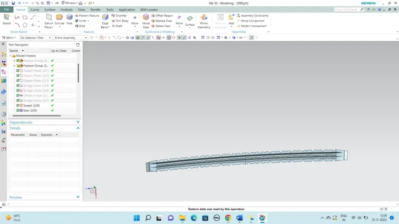
The bow roofs are given to the improve the torsional stiffness and load bearing capacity of the roof structure. When number of bow roofs are given by the roof dimension. Longer the roof area we have to give the more bow roof to the structure. Positioning of the bow roofs are decided by the curvature study. The Heat distortion and Snow load criteria are checked to analyse the bow roof position by various condition. The Mastic area for fixing the Bow roof to the roof outer.
CENTER ROOF RAIL:
Center roof rail is effective support to the flat area structure roof. Because of center area of roof is more susceptible to failure under action of load. Usually, Reinforcement center roof rails are fixed at the center of the roof for connecting to the B – Pillar support structure, it will used for roll-over test. Center bow roof and reinforcements are placed at the center of the roof structure. They two are connecting to help of spot - welding operation.
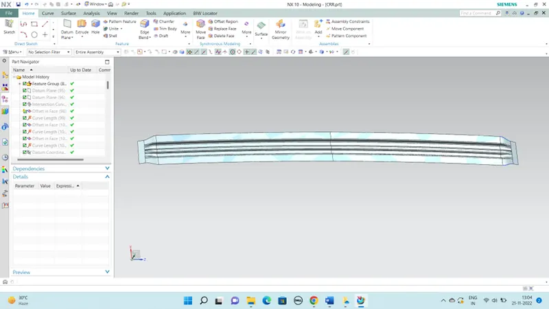
REAR BOW ROOF:
The rear bow roofs are given to the improve the torsional stiffness and load bearing capacity of the roof structure. When number of bow roofs are given by the roof dimension. Longer the roof area we have to give the more bow roof to the structure.
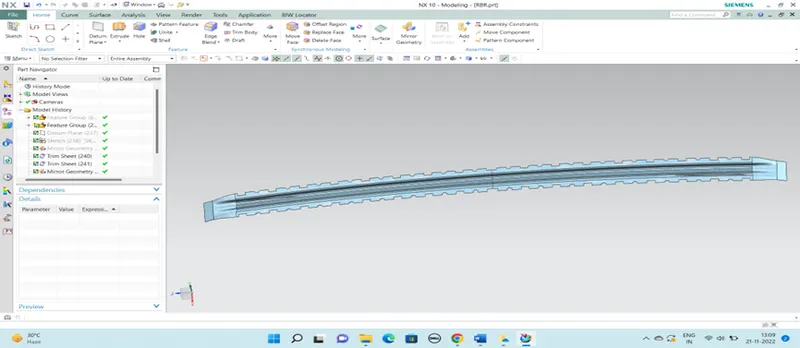
REAR ROOF RAIL:
Rear roof rail is creating to length 80-100mm with proper draft angle. Give embosses on the sheet to ensure the enough strength for holding the roof structure. When considering the all parameters like length, width, sealants, rubber materials, wind shield to create the design properly.

MASTIC SEALENTS:
The Mastic sealant or the Mastic point is an elastic compound that behaves like a rubber. The mastic sealants are applied at the many places like roof outer to front roof rail, rear roof rail, bow roof and reinforcement center roofs. They help the roof outer panel to come back to its original shape after it gets deformed. The mastic has an influence area of 80mm.
HEAT DESTORATION:
The heat distortion study the plays an important role in Sheetmetal application. Heat distortion is temperature limit above which material cannot be used for structural application. This study is useful to fin the where the material starts to soften when exposed to a fixed load at elevated temperature. In order to avoid the bending, damage to the roof based on the heat distortion temperature. This study will provide the which position of the bow roof give enough strengthen to roof.
W = [1.73 x 10^(-3) x L] + [1.85 x 10^(-8) x (R^2)/t] + [ 1.10x10^(-3) x l] - 2.68
Where,
L = Roof Length in X-Direction[mm](Roof dimension in 0-Y)
R = Roof curvature
R = 2(Rx*Ry)/(Rx+Ry)
Rx = X curvature
Ry = Y curvature
t = Roof plate thickness [mm]
l = Bow Roof Span [mm]
Judgment Condition
OK< 2.7
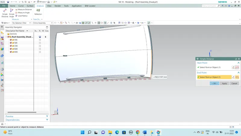
ROOF LENGTH L = 1923.1107mm
|
BOW ROOF POSSISTION |
RX |
RY |
R |
I |
L |
t |
W |
JUDGEMENT CONDITION
|
|
FR – 1 BOW |
5625.33 |
3067.60 |
3969.5 |
448.55 |
1923.11 |
0.75 |
1.52 |
Ok |
|
1 BOW-CNT |
4852.22 |
6621.38 |
5591.98 |
364.98 |
1923.11 |
0.75 |
1.81 |
Ok |
|
CNT–2 BOW |
4062.85 |
10588.25 |
5874.66 |
466.3 |
1923.11 |
0.75 |
2.01 |
Ok |
|
2 BOW-RR |
3426.25 |
14484.58 |
5601.20 |
356.51 |
1923.11 |
0.75 |
1.81 |
Ok |
From the above table we, conclude that all the values are of W< 2.7, so that all bow roofs areas are placed at the right place.
SNOW LOADCRETERIA:
Snow Load Prediction Formula
Qr = [Iy x t2] / [α x s x [(Rx + Ry)/2]2 x 10-8]
Note: The Qr value given over here is correct. There was a typo error in the formula given in the video.
Where,
α = My x Lx2 x 10-12 , My = Y(Ly-Y)
t = Roof plate thickness [mm]
Ly = Distance between the front and rear roof Rails on the Vehicle along with 0Y[mm]
Length of Roof panel with the center point between Roof rail Front /Rear as the front and rear reference point.
Lx = Distance between the Left and Right end of the roof on the Roof BOW [mm]
The width of the roof panel is exposed on the surface.
Y = Distance front Front Roof Rail to Roof BOW[mm]
s = Distance for which Roof BOW bears divided load [mm]
s = L1/2 + L2/2
Iy = Geometrical moment of inertia of Roof BOW (Y cross-section )[mm4]
Rx = Lateral direction curvature radius of roof panel Y cross-section on Roof BOW [mm]
Roof panel curvature Radius of the Length Lx in Front view
Ry = Longitudinal Direction curvature radius of the Roof panel X cross-section on Roof BOW [mm]
Roof panel X curvature radius of length s in Side view
Judgment condition
Qr ≥ 3.1
250 ≤ s ≤ 380
|
ROOF RAILS |
IY (mm) |
LX (mm) |
LY (mm) |
L1 (mm) |
L2 (mm) |
RX (mm) |
RY (mm) |
T (mm) |
Y (mm) |
S |
MY |
α |
Q |
RESULT |
|
FR – 1 BOW |
198.802 |
1074.32 |
2030.22 |
442.56 |
418.6 |
4356.77 |
2868.33 |
0.75 |
1432.05 |
432.4 |
857598.20 |
0.9833 |
22.378 |
PASS |
|
1 BOW -CRR |
466.81 |
1060.95 |
2032.25 |
420.55 |
318.82 |
3796.58 |
6598.01 |
0.75 |
515.21 |
368.98 |
7805.5548 |
0.8825 |
13.25 |
PASS |
|
CRR – 2 BOW |
198.98 |
1055.36 |
2021.98 |
320.01 |
300.01 |
4299.56 |
11550.82 |
0.75 |
425.01 |
308.662 |
672536.01 |
0.80461 |
9.85 |
PASS |
SECTION MODULUS:
The moment carrying capacity of an object is directly dependent on geometrical property (I) and material property (E) of an object, which is collectively termed as flexural rigidity (EI). Geometry of an object plays an important role in load bearing capacity of an object which is indicated by moment of inertia of a section.
Section modulus is a direct measure of strength of any sectional area of an object about a reference axis. This strength can be measured directly from Section modulus formula.
Formula of Section Modulus: It may be defined as the ration of total moment resisted by the section to the stress in the extreme fibre which is equal to yield stress.
S = I / Y
Where,
S - Section modulus.
I -Moment of inertia.
Y -The distance from the reference line (neutral axis) to one of the extreme ends of an object.
MOMENT OF INERTIA:
FRONT ROOF:
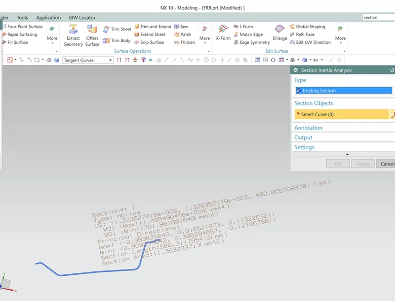
Imax = 1.495490456e+004 [mm4]
Imin = 701.861681649[mm4]
Y = TOTAL LENGTH / 2
Y = 120.97 / 2
Y = 60.48mm
For Imax
S = I /Y
S = = 1.495490456e+004 [mm4]/60.48mm
S = 247.27mm3
For Imin
S = I /Y
S = 701.861681649[mm4] / 60.48mm
S = 11.60 mm3
FRONT BOW ROOF:
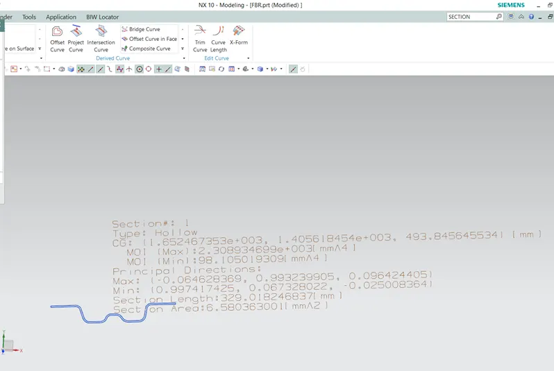
Imax = 2.308934699e+003 [mm4]
Imin = 98.1050193091[mm4]
Y = TOTAL LENGTH / 2
Y = 66.6342 / 2
Y = 33.31mm
For Imax
S = I /Y
S = = 2.308934699e+003 [mm4]/33.31mm
S = 69.31mm3
For Imin
S = I /Y
S = 98.1050193091[mm4] /33.31mm
S = 2.945mm3
CENTER ROOF:
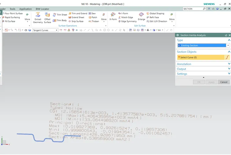
Imax = 5.406435955e+003 [mm4]
Imin = 133.0644989201[mm4]
Y = TOTAL LENGTH / 2
Y = 89.9264 / 2
Y = 44.9632mm
For Imax
S = I /Y
S = = 5.406435955e+003 [mm4]/44.96mm
S = 120.24mm3
For Imin
S = I /Y
S = 133.0644989201[mm4]/44.96mm
S = 2.959mm3
REAR BOW ROOF:
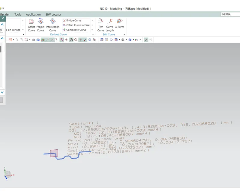
Imax = 2.301659838e+003 [mm4]
Imin = 98.459966067[mm4]
Y = TOTAL LENGTH / 2
Y = 66.56 / 2
Y = 33.28mm
For Imax
S = I /Y
S = = 2.301659838e+003 [mm4]/33.28mm
S = 69.16mm3
For Imin
S = I /Y
S = 98.459966067[mm4]/33.28mm
S = 2.95mm3
REAR ROOF RAIL:
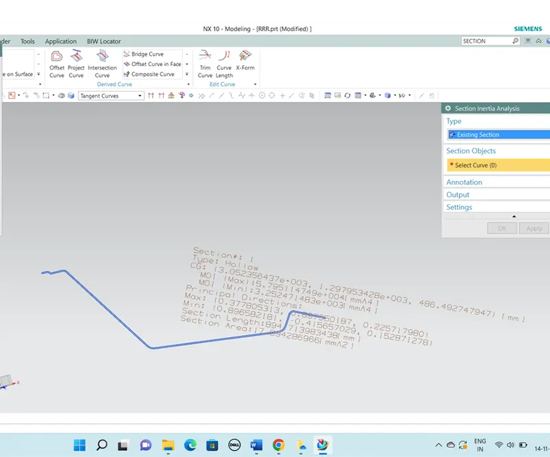
Imax = 5.795114749e+004 [mm4]
Imin = 3.252471483 e+003[mm4]
Y = TOTAL LENGTH / 2
Y = 195.8188 / 2
Y = 97.90mm
For Imax
S = I /Y
S = = 5.795114749e+004 [mm4]/97.90mm
S = 591.94mm3
For Imin
S = I /Y
S = 3.252471483 e+003[mm4]/97.90mm
S = 33.22mm3
CONCLUSION:
The roof design, check heat distortion and snow load condition for bow roofs are placed at right place or not. So, after finishing my design I calculate the heat distortion and snow load condition. After, finishing the curvature study. Then I check the section modulus of the each section.