Roof Design
INTRODUCTION
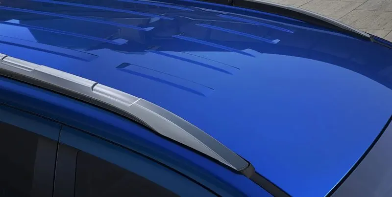
The roof of a car or other vehicle is the top part of it, which protects passengers or goods from the weather. The roof also protects the passenger from any injury when the car gets crashed or is rolled over or something heavy falls on the roof.
OBJECTIVE
The main objective of this project is to understand the design process to design the roof with all the rails and to understand the calculations behind it. We also get to learn about the different tools used in NX-CAD for designing.
METHODOLOGY
We get the model of the roof of the from the styling team. Then we will have to do all the engineering work. We create the ditch area for the roof and also the roof bows and roof rails for the roof which would we designed by us considering all the safety norms and regulations.

DESCRIPTION
DESIGN CONSIDERATION-
- Visibility criteria
- Head clearance
- Curvature study
- Hear distortion and snow load criteria
- Draft analysis
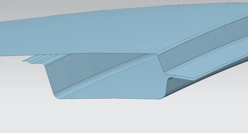
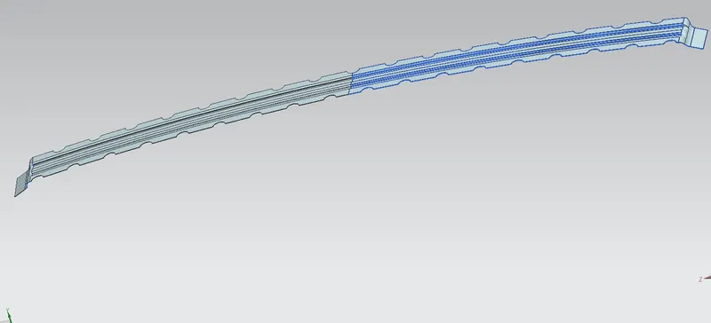
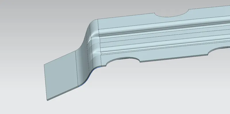
1 Front Roof Rail-
The front roof rail is located on the front of the roof where the wind shield joins with the roof, The visibility criteria and the head room clearance of the passenger are taken into consideration for the bottom flange. One and of the rail is joined using spot welding while the other end is joined with the roof using mastic sealants for increased strength.
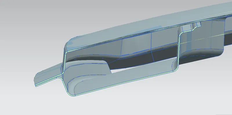
2. Bow Roof 1-
Bow roof is an additional stiffening member for the roof to increase the strength and so that it can satisfy the norms. Both the ends are joined together using mastic sealants to increase strength and also sine this would not affect the styling of the roof
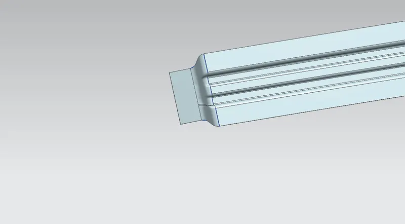
3. Centre Roof Rail-
Centre roof rail or the reinforcement center is located at the center of the roof. The cross section of this is more since it needs to provide more strength to the roof. Here both are ends are joined together using mastic sealants.
4. Bow Root 2
This bow root also has the same purpose as that of the first one. This one is located between the centre bow root and rear roof rail
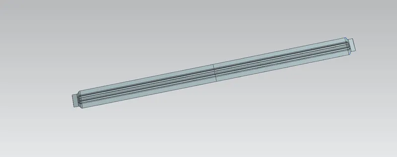
5. Rear Roof Rail
This root rail joins with the back door and roof. Inputs from the backdoor are taken into consideration for designing this roof rail.
Here one and is joined using spot welding while the other end is joined using mastic sealants.
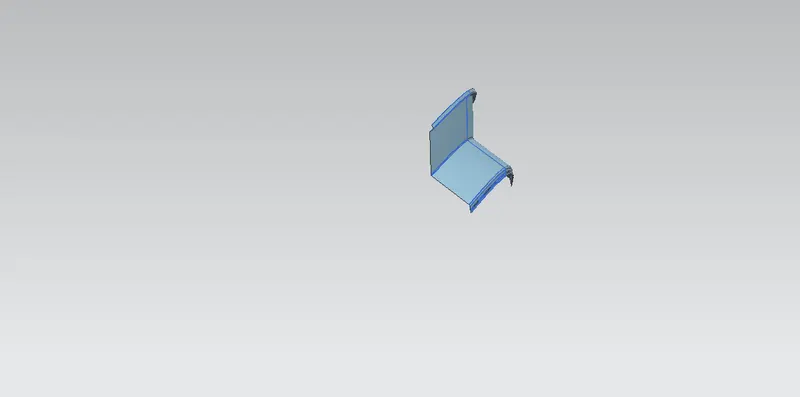
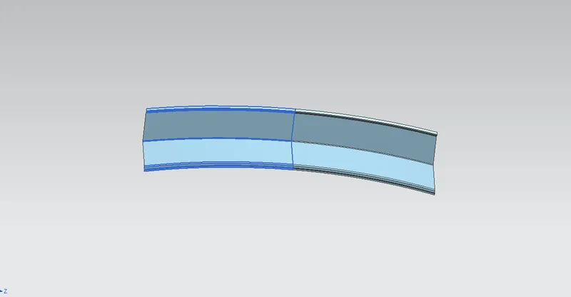
Ditch area the extended portion of the main roof concealed by other BIW panels.
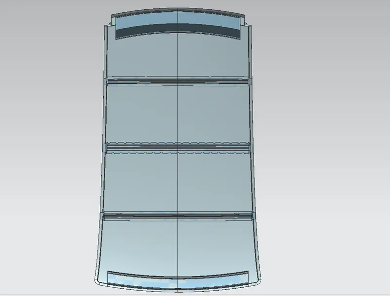
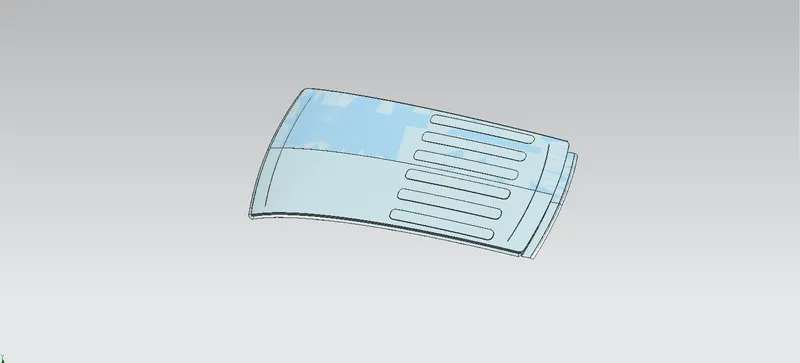
CALCULATIONS
Heat Distortion curvature Study-
This study is used to find out and predict the heat distortion temperature at where the material starts to soften when exposed to a fixed load. So, in order to avoid bending or damage of the roof based on this calculation we will decide the position on the roof bows on the roof.
Formula-
W = [1.73 x 10^(-3) xL]+[1.85 x 10^ (-8) x (R^2)/t] + [1.10 x 10^ (-3)xl] -2.68
Judgement condition: OK (2.7>3.1
Where
L= roof length in X-direction/mm) (roof dimension in 0-v)
R= roof curvature
R=2(Rx Ry)/ (Rx + Ry)
Rx=X curvature
Ry= Y curvature
t= roof plate thickness [mm]
l = bow root span [mm]
Result
| Sr.no | Bow | Rx | Ry | R | l | t | W | Judgement |
| 1 | FRR & 1st Bow | 5787.8971 | 2816.4945 | 3789.1289 | 416.3133 | 0.75 | 1.655 | ok |
| 2 | 1st Bow & CRR | 5240.2692 | 6386.9479 | 5757.0655 | 429.989 | 0.75 | 2.1334 | ok |
| 3 | CRR & 2nd Bow | 4179.1618 | 11290.3159 | 6100.2779 | 418.1832 | 0.75 | 2.2208 | ok |
| 4 | 2nd Bow & RRR | 3428.5520 | 16354.2834 | 5668.7031 | 323.1805 | 0.75 | 1.9910 | ok |