Roof Design
OBJECTIVE:
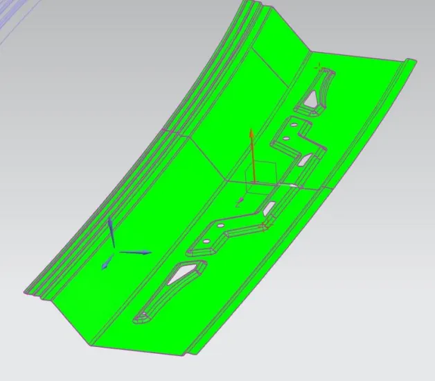
Design a roof using the provided skin data and also position bow roof rails in accordance with heat distortion and snow weight formula also to find section modulus of the roof and roof rails and check the draft of the designed parts.
Given Surface:
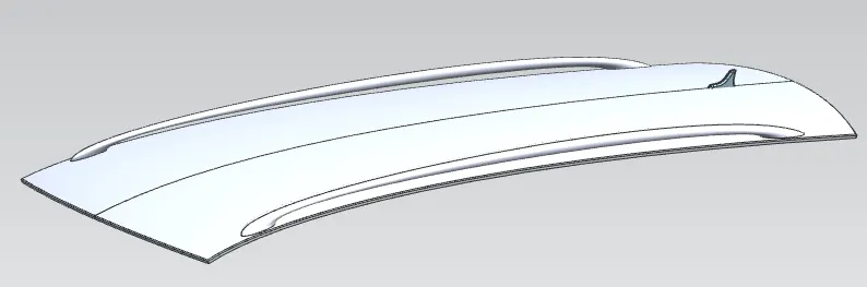
Roof :
An automobile roof or car top is the portion of an automobile that sits above the passenger compartment, protecting the vehicle occupants from sun, wind, rain, and other external elements. Because the earliest automobiles were designed in an era of horse-drawn carriages early automobile roofs used similar materials and designs.
- Convertible roofs. Roof modules. Roof modules.
- Hardtops.
- Sunroofs.
- T-tops.
- Targa tops.
- Vinyl roofs.
Some roofs have a window on them and are called sunroofs, while convertibles have special mechanisms that allow the roof to be retracted and be stowed away through a wide array of methods depending on the design.
The roof of the car is made up of multiple parts that provide support and strength to the roof component. The actual roof sheet and the roof rails support the roof sheet. There are 3 primary roof rails in a car the front, the center, and the rear, while additional roof rails are called Bow roof rails. The number of bow roof rails depends on the size of the roof. Headroom, visibility criteria, and target region also play a key role in roof design.
PARTS OF VEHICLE ROOF.
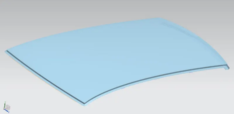
ROOF OUTER PANEL:
The roof is made from a sheet of at least 0.75mm. This protects the cabin from external conditions and objects. The ditch areas are spot welded to the pillars of the car and certain areas of the roof rails, welding on the upper surface is avoided in order to maintain a good aesthetic. It is present at a clearance above passenger head, for providing protection against sun rays, rain, wind and external elements. It supports the internal structural members like, front roof rail, bow roof rail, centre roof rail and rear roof rail, thus providing the strength to the outer panel structure.
FRONT ROOF RAIL:
The front roof rail is used to provide strength to the roof panel front and it also acts as a link between windshield glass, roof panel, and headliner(interior trim). It is the first segment of internal structure for roof. The Front roof rail is mainly designed based on Headroom clearance and Driver visibility for viewing the front road. It is created by the help of flanges, followed by development of emboss parts on front roof rail for providing the strength. There is a clearance of 5mm provided in between the outer roof panel and the front roof rail, for joining through mastic sealant.
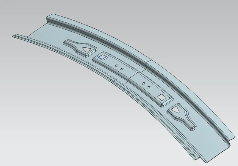
BOW ROOF RAIL:
Bow Roof Rail is the second segment of internal structure for outer roof panel, followed by Front Roof Rail. There are totally two Bow Roof Rails are developed, based on the length of outer roof panel. The Two Bow roof rails are placed in between the centre roof rail to provide the distributed strength for outer roof structure. There is a clearance of 5mm provided in between the outer roof panel and the bow roof rail, for joining through mastic sealant.
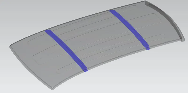
CENTER ROOF RAIL:
Centre Roof Rail is the third segment of internal structure for outer roof panel, in between two Bow Roof Rails. The Centre roof rail comes with an additional reinforcement to provide high strength for roof, as the centre roof rail is present at the middle/centre part of the vehicle roof. There is a clearance of 5mm provided in between the outer roof panel and the centre roof rail, for joining through mastic sealant.
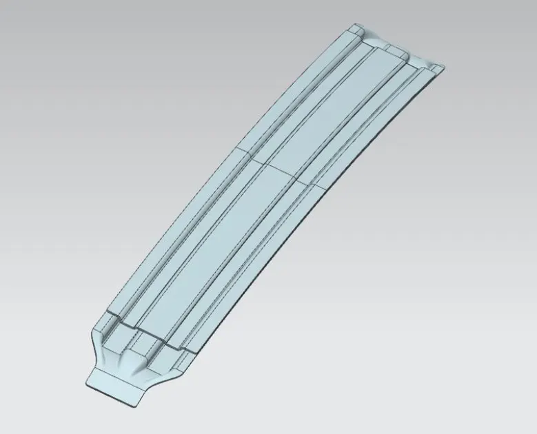
REAR ROOF RAIL:
This roof rail joins with the back door and the roof. Inputs from the backdoor are taken into consideration for designing this roof rail. Here one end is joined using spot welding while the other end is joined using mastic sealants.
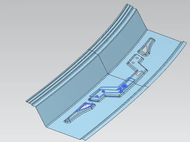
DESIGN CALCULATION OF ROOF.
The criteria for judging the right design for roof is based on the following two judgement conditions,
1) Heat Distortion Criteria.
2) Snow Load Criteria.
1) Heat Distortion Criteria.
The roof of the vehicle is the most exposed to changes in temperature, these changes cause deformation in the roof. In order to prevent failure of the roof due to excessive thermal stress, the roof rails must be placed in the correct locations. Improper designing of the roof may cause warping, cracking, and failure of mounts.
- This calculation is done to find if the roof under thermal stress deforms within set limits.
- It is calculated using the formula
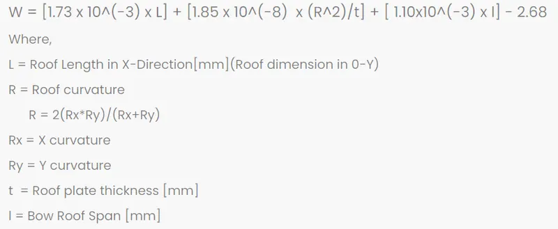
The results obtained for the designed roof after incorporating the values of design parameters in bow prediction formula is shown in below table,
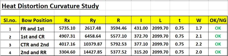
Conclusion of Heat Distortion Criteria:- The Designed Roof satisfies the Bow roof prediction formula for the considered Bow positions.
2) SNOW LOAD CRITERIA:
Snow load is the downward force on a roof by the weight of accumulated snow and ice. The roof or the entire structure can fail if the snow load exceeds the weight the roof was designed to shoulder. Or if the roof was poorly designed or constructed.
The roof of a vehicle is normally not designed to hold up weight but for regions with snowfall, it must be properly reinforced to hold up the weight of accumulated snow on the roof, if done improperly it may cause the roof to bend and intrude into the passenger compartment which is dangerous. This calculation is done in order to check if the location and strength of the roof rails are enough to avoid plastic deformation of the roof.
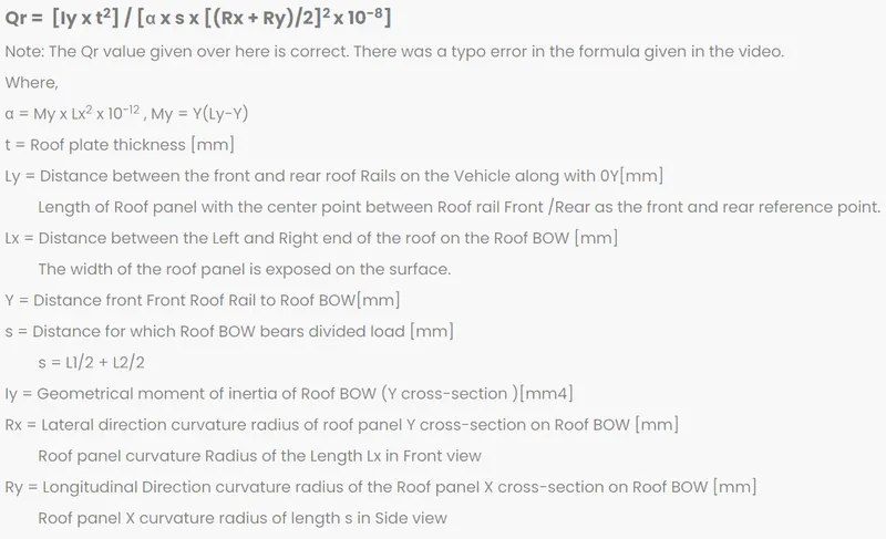
The results obtained for the designed roof after incorporating the values of design parameters in snow load prediction formula is shown in below table,


Conclusion of Snow Load Criteria:- The Designed Roof satisfies the Snow Load criteria only for Bow position of 1st bow roof rail and Centre roof rail as shown in sl. No. 2.
Henceforth, to increase the strength of the roof in terms of snow load criteria, necessary embosses are to be created on outer roof panel.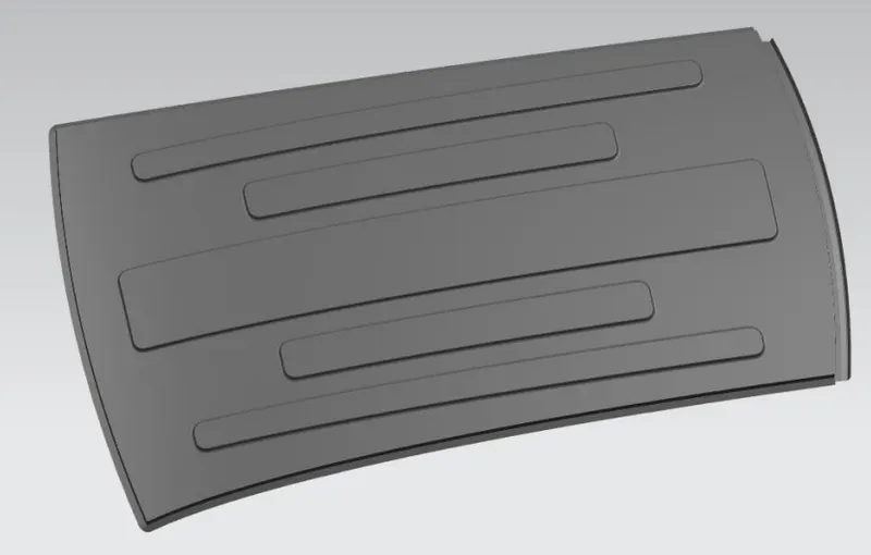
SECTION MODULUS ANALYSIS FOR ROOF PARTS.
Section Modulus analysis on Bow roof rail – 1 (Position - after the front roof rail).
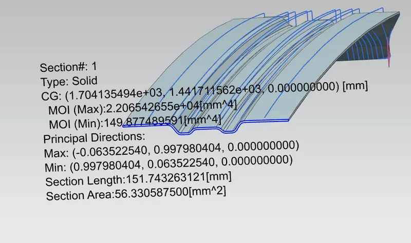
Section Modulus analysis on Centre Roof Rail (Position - after the Bow roof rail – 1).
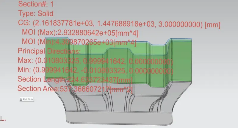
Section Modulus analysis on Bow roof rail – 2 (Position - after Centre Roof Rail).
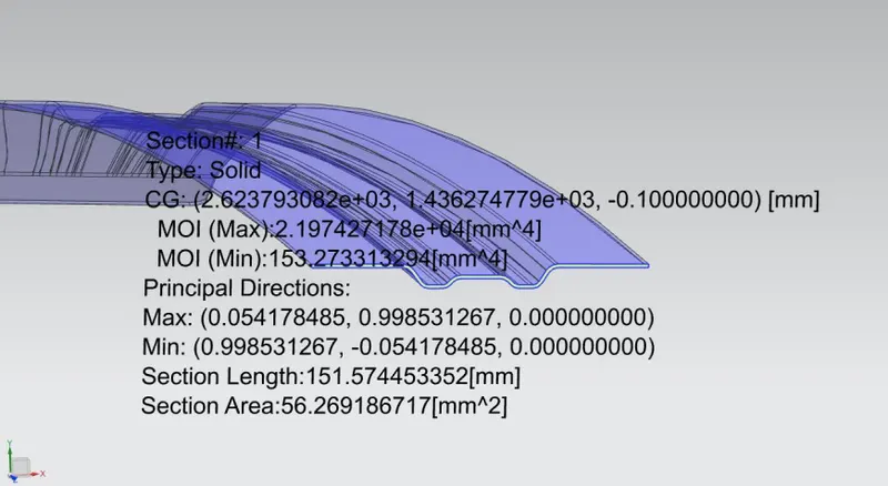
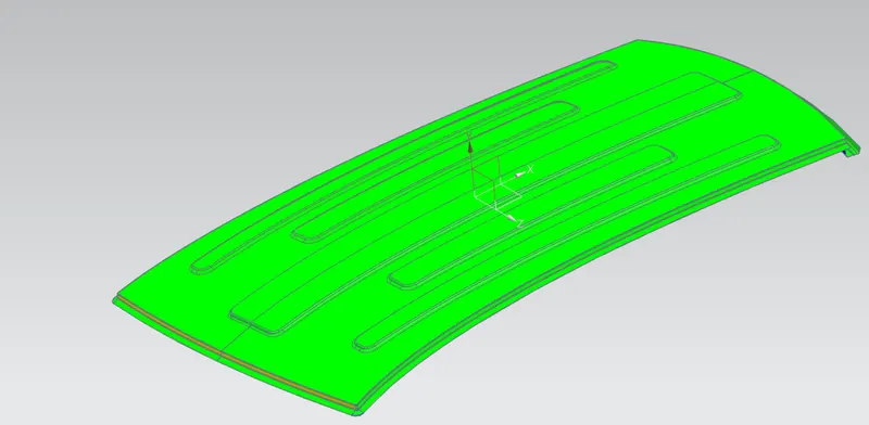
DRAFT ANALYSIS FOR ROOF PARTS.
Outer roof panel.
Front Roof Rail.
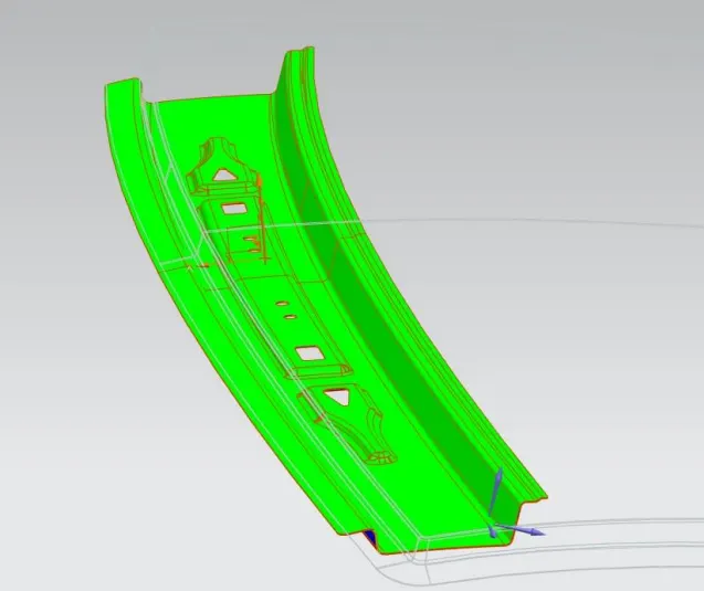
Bow roof-1.
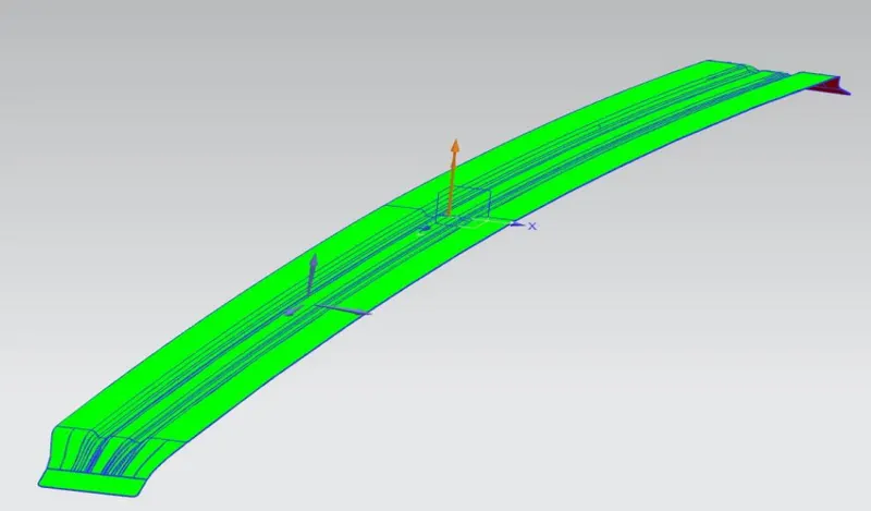
Centre roof rail.
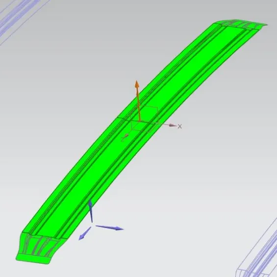
Bow roof-2.
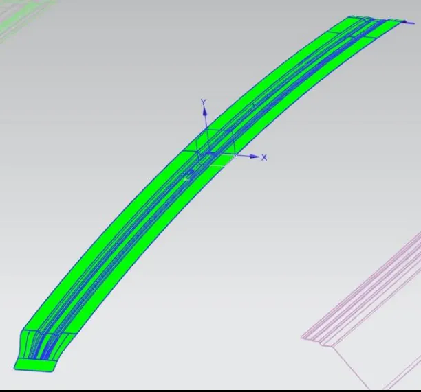
Rear roof Rail.