Roof Design
ROOF CHALLENGE:
Introduction:
The roof part which starts from A-pillar and goes upto D-pillar.The roof purpose is to provide cover to the passenger inside the car and protect the passenger from elements like sun,rain,wind,etc.The roof also prevents unwanted object from falling inside the car.Roofs are generally made up of Aluminium.Aluminium based roof panel may reduce the overall weight of the assembly.
AIM: To a given roof styling, create essential flanges and reinforcements.
Objective: To develop the essential flanges and reinfocements with appropriate dimensions and checking draft by using draft analysis. Calculating the Heat distortion, Snow load and section inertia on roof.
Software Used: NX CAD
Types of Automobile roof:
- Convertible:A convertible ,cabriolet or spyder is a passenger car that can be driven with or without a roof in place.
- Hardtop:A hardtop is a rigid form of automobile roof,which for modern cars typically constructed from metal.A hardtop roof can be either fixed,detachable for separate storing or retractable within the vehicle itself.
- Sunroof:An Automotive sunroof is a movable panel that is operable to uncover a window in an automobile roof.which allows light and fresh air into the passanger compartment.
- T-top: A T-top is an automobile roof with a removable panel on each side of a rigid bar running from the center of one structural bar between pillars to the center of the next structural bar. The panels of a traditional T-top are usually made of auto grade safety glass.
- Targa Top: Itis a semi-convertible car body style with a removable roof section and a full width roll bar behind the seats.
- Vinyl roof:Vinyl roof refers to a vinyl converting for a automobile’s top.This converting was orginally designed to give the appearance of a convertible to models with a fixed roof but eventually,it evolved into styling statement in its own right.
Design Consideration:
- Visibility criteria
- Head clearence
- Curvature study
- Heat distortion and snow load condition
Components of roof:
- Front roof rail
- Rear roof rail
- Bow roof
- Centre roof rail
- Ditch area
For the Given Roof styling, create an ASSEMBLY by developing the essential flanges for the outer roof and creating the reinforcements.
Provide appropriate dimensions and check for Draft analysis.
Do a curvature study on the roof and perform calculations to determine the position of the Bow-roofs.
Suggest and implement remedies in the design if the criterion is not full-filling
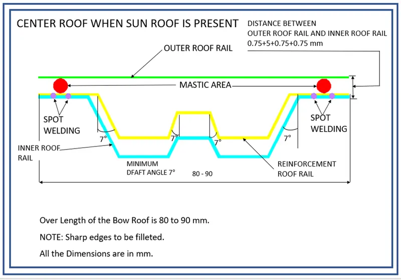
Start with the creation of a roof ditch area with a tool opening angle of 7 degrees.
Develop the reinforcements as separate parts
Bow–Roof Prediction Formula
W = [1.73 x 10^(-3) x L] + [1.85 x 10^(-8) x (R^2)/t] + [ 1.10x10^(-3) x l] - 2.68
Where,
L = Roof Length in X-Direction[mm](Roof dimension in 0-Y)
R = Roof curvature
R = 2(Rx*Ry)/(Rx+Ry)
Rx = X curvature
Ry = Y curvature
t = Roof plate thickness [mm]
l = Bow Roof Span [mm]
Judgment Condition
OK< 2.7
Snow Load Prediction Formula
Qr = [Iy x t2] / [α x s x [(Rx + Ry)/2]2 x 10-8]
Note: The Qr value given over here is correct. There was a typo error in the formula given in the video.
Where,
α = My x Lx2 x 10-12 , My = Y(Ly-Y)
t = Roof plate thickness [mm]
Ly = Distance between the front and rear roof Rails on the Vehicle along with 0Y[mm]
Length of Roof panel with the center point between Roof rail Front /Rear as the front and rear reference point.
Lx = Distance between the Left and Right end of the roof on the Roof BOW [mm]
The width of the roof panel is exposed on the surface.
Y = Distance front Front Roof Rail to Roof BOW[mm]
s = Distance for which Roof BOW bears divided load [mm]
s = L1/2 + L2/2
Iy = Geometrical moment of inertia of Roof BOW (Y cross-section )[mm4]
Rx = Lateral direction curvature radius of roof panel Y cross-section on Roof BOW [mm]
Roof panel curvature Radius of the Length Lx in Front view
Ry = Longitudinal Direction curvature radius of the Roof panel X cross-section on Roof BOW [mm]
Roof panel X curvature radius of length s in Side view
Judgment condition
Qr ≥ 3.1
250 ≤ s ≤ 380
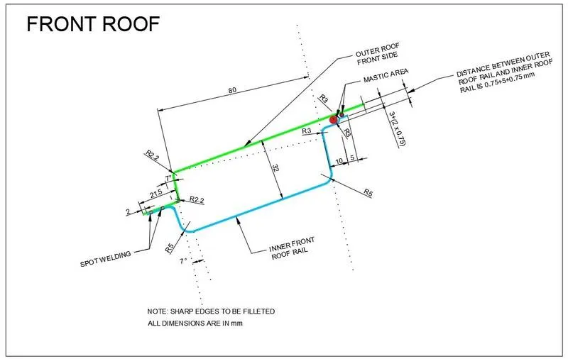
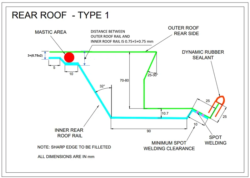
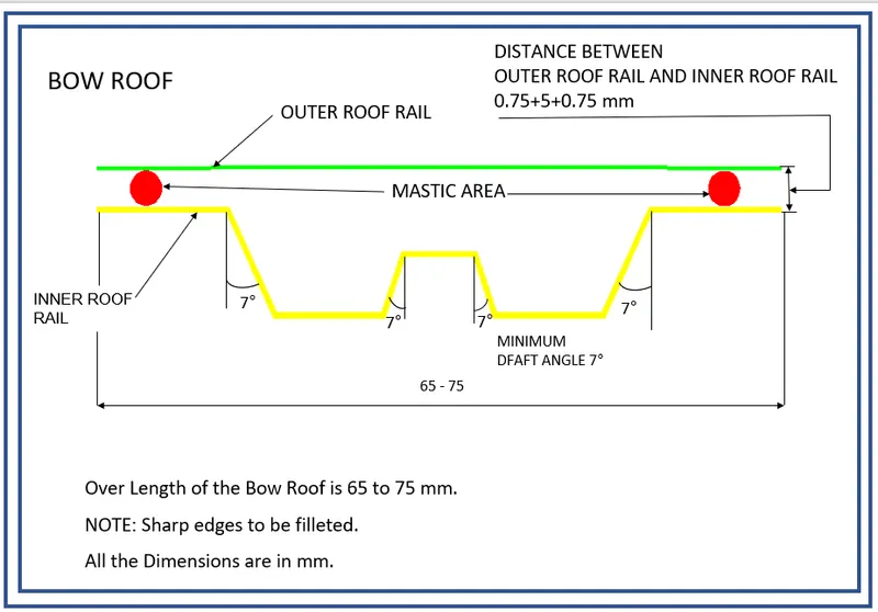
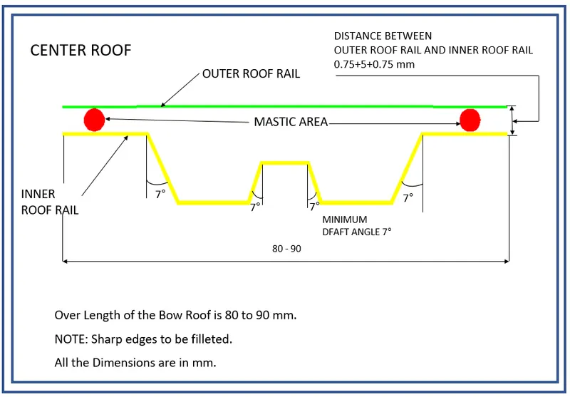
Here are some Reference images for the Master sections - These images are just to give you a brief idea about the design.
Front Roof Rail Master section
Master section of the Rear Roof Rail
Master section of Bow Roof
Master section of Center Reinforcement Rail
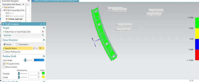
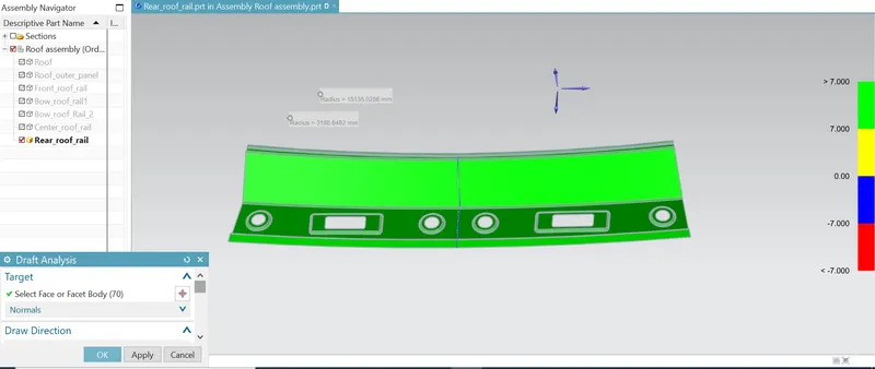
DRAFT ANALYSIS
Front roof rail
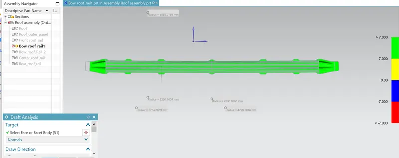
BOW ROOF 1
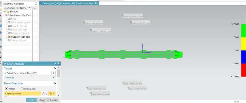
Center roof
BOW ROOF 2
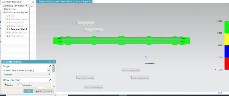
Rear Roof Rail
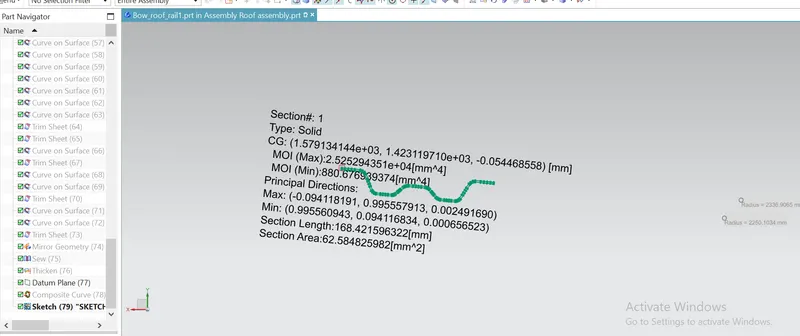
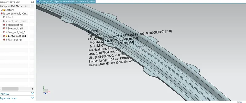
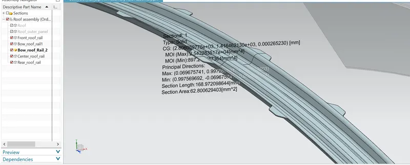
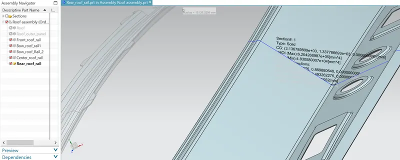
Moment of INERTIA
BOW ROOF 1
CENTER ROOF RAIL
BOW ROOF 2
REAR ROOF RAIL
CALCULATION
HEAT DISTORTION

SNOW LOAD

Learning:
- Here we learned how to create a rails with the given standards by using Master Sketch.
- Learned How to calculate Heat Disorsion and Snow load criteria
- Learned how to do Draft analysis.
Conclusion:
The roof was created with all required parameters with a certain rails, and calculation the heat distortion, snow load are done and performed Draft analysisfor safety concerns. The result is satisactory.