Roof Design
AIM:
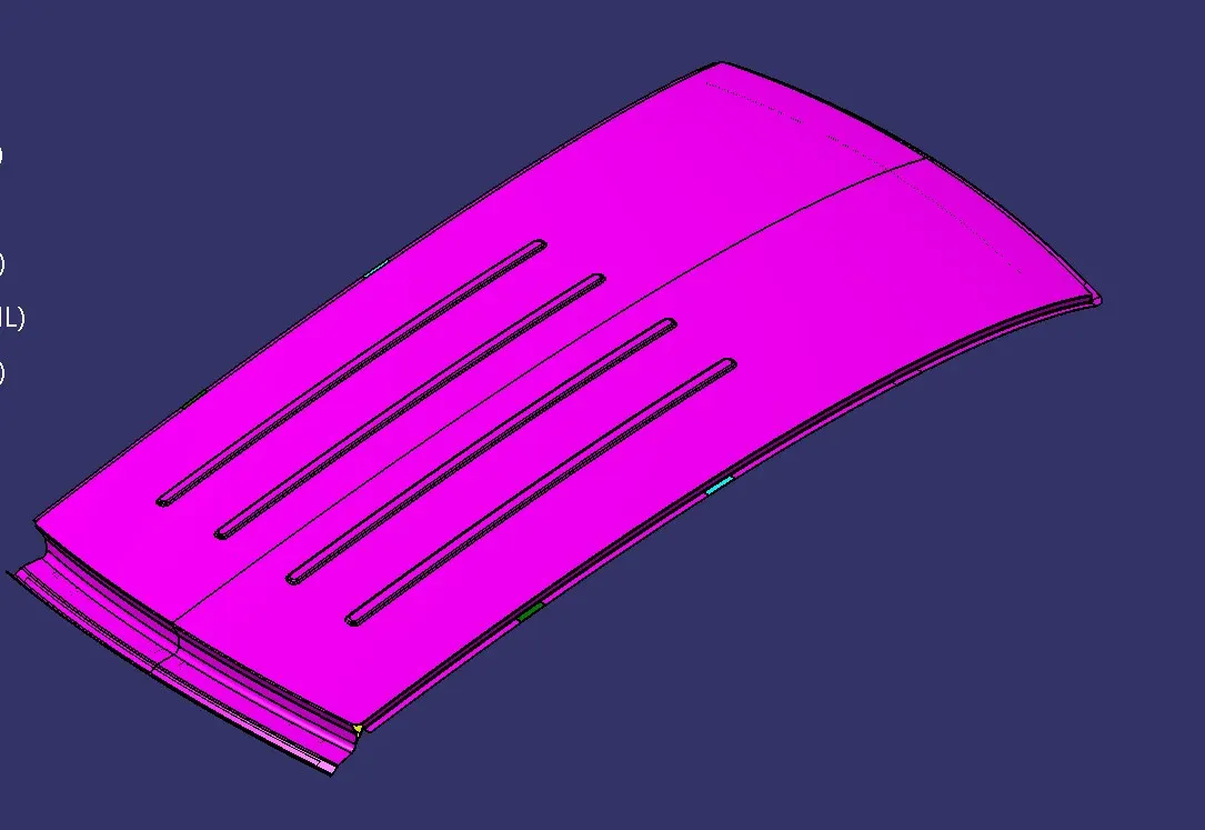
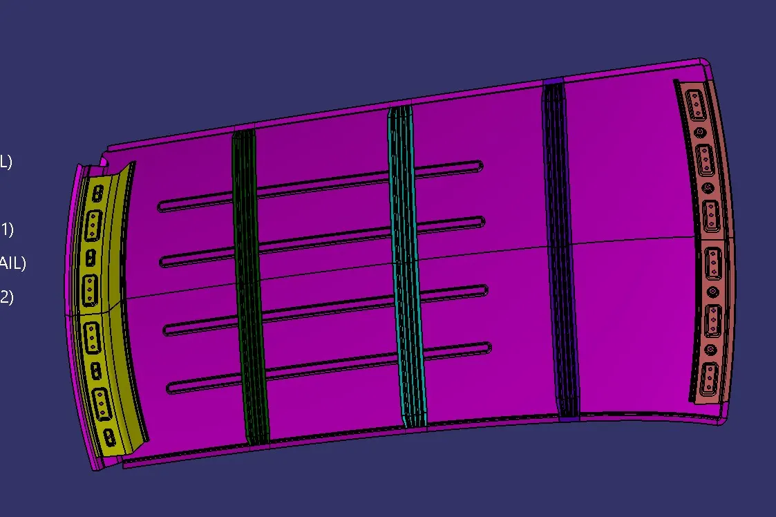
To design and develop the Roof of a car with its components like front roof rail, bow roof rails, center roof rail, rear roof rail by following the given master section and design parameters.
INTRODUCTION:
In automotive design, the roof serves several important functions beyond simply covering the passenger compartment. Here's an introduction to roof design in cars.
Structural Integrity of the roof of a car contributes significantly to the overall structural integrity and safety of the vehicle. It helps to maintain the rigidity of the body structure, which is crucial for protecting occupants in the event of a rollover or impact.
Aerodynamics shape and design of the roof affect the aerodynamic performance of the vehicle. Automotive engineers strive to optimize the roof design to minimize drag and improve fuel efficiency. Smooth, streamlined roof contours help reduce wind resistance and enhance vehicle stability at high speeds.
Styling and Aesthetics of the roof design plays a key role in defining the exterior styling and aesthetics of the vehicle. Automakers carefully consider factors such as roofline curvature, roof height, and the integration of features like sunroofs or roof rails to achieve a distinctive and attractive appearance.
Interior Space and Comfort of the roof design also influences the interior space and comfort for passengers. Factors such as headroom, visibility, and the placement of structural components (such as pillars) affect the overall cabin layout and passenger experience.
Functionality of Modern cars often incorporate various features into the roof design to enhance functionality and convenience. These may include panoramic sunroofs for increased natural light and a sense of openness, roof rails for mounting cargo carriers or roof racks, and integrated antennas or satellite receivers for communication and entertainment systems.
Material Selection of Automotive manufacturers utilize a variety of materials in roof construction, including steel, aluminum, carbon fiber, and composite materials. Each material offers different strengths in terms of strength, weight, cost, and manufacturing feasibility, allowing designers to tailor the roof design to meet specific performance and cost targets.
Overall, roof design in cars involves a careful balance of structural, aerodynamic, aesthetic, and functional considerations to create a vehicle that is safe, efficient, comfortable, and visually appealing. Advances in design technology and material innovation continue to drive ongoing improvements in automotive roof design.
TYPE OF CAR ROOF:
- Convertible roofs
- Hardtops
- Sunroofs
- T-tops
- Targa tops
- Vinyl roofs
FMVSS 216 Roof crush standards:
FMVSS 216, Roof Crush Resistance, establishes strength requirements for the passenger compartment roof of passenger cars, multipurpose passenger vehicles, trucks, and buses with a GVWR of 2722 kilograms or less. The purpose of the standard is to reduce deaths and injuries due to the crushing of the roof into the passenger compartment in rollover accidents. The standard does not apply to school buses and passenger cars that conform to the dynamic rollover test requirements of FMVSS 208, Occupant Crash Protection, and S5.3 by means that require no action by passenger car occupants. It also does not apply to convertibles, except for optional compliance with the standard as an alternative to the rollover test requirements in S5.3 of FMVSS.
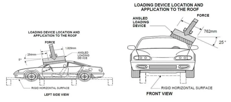
The prescribed static loading device is a rigid unyielding rectangular block 762 millimeters by 1,829 millimeters. It shall not move more than 127 millimeters to achieve the specified resistive load when applied to the forward edge of a vehicle’s roof – see Figures 1 and 2. The resistive load to be achieved is 1½ times the unloaded vehicle weight (UVW) of the test vehicle or 22,240 Newtons, whichever is less.
The force shall be applied in a downward direction perpendicular to the lower surface of the static loading device at a rate of not more than 13 millimeters per second until reaching the compliant resistive load. The test shall be completed within 120 seconds. The static loading device shall be guided throughout the test so that it moves, without rotation, in a straight line with its lower surface oriented as follows and as shown in Figures.
DESIGN OBJECTIVE:
- To develop the essential flanges using roof skin data as input.
- To do a curvature study on the roof and perform calculations to determine the position of the Bow-roof.
- To determine the Heat Distortion Criteria of the car's roof.
- To find the section modulus on the O-Y section of the roof and also for all the other components of it.
- To determine the Snow Load Criteria for a car's roof.
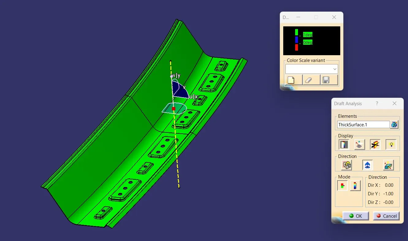
- To perform a Draft Analysis on the final model of the roof.
TO DESIGN THE CAD MODEL:
We will be having the Aesthetic Surface skin data which is provided by the styling team.
Taking it as a reference we can start the design and at the same time we need to follow the Master Section.
1.Roof: An automobile roof or car top is the portion of an automobile that sits above the passenger compartment, protecting the vehicle occupants from sun, wind, rain, and other external elements.
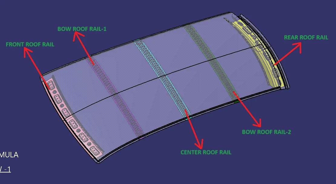
2.Front Roof Rail: Front roof rail is the additional commodity which acts as reinforcement also it has certain features in it which will be supporting bracket maplamp and room lamp
3.Rear Roof Rail: Rear roof rail is mainly supporting the roof. And also the back door hinges in order to make opening and closing.
4.center Roof Rail: Is the main supporting member of the roof where it helps to absorb energy at the time of side crash. Also it acts as a bow roof for small cars.
5.Bow Roofs: This is the roof supporting rails, which are provides additional stiffness, designed based on Heat Distortion Criteria and Snow load Condition.
First to create the front roof flange in the outer panel with the consideration of given master section image shown below.
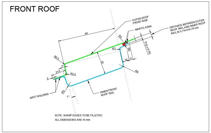
Initially, we need to create the ditch area for the outer panel in the front and back
At the corners use a multisection Surface to get smooth corners which will increase the strength and easy to manufacture.
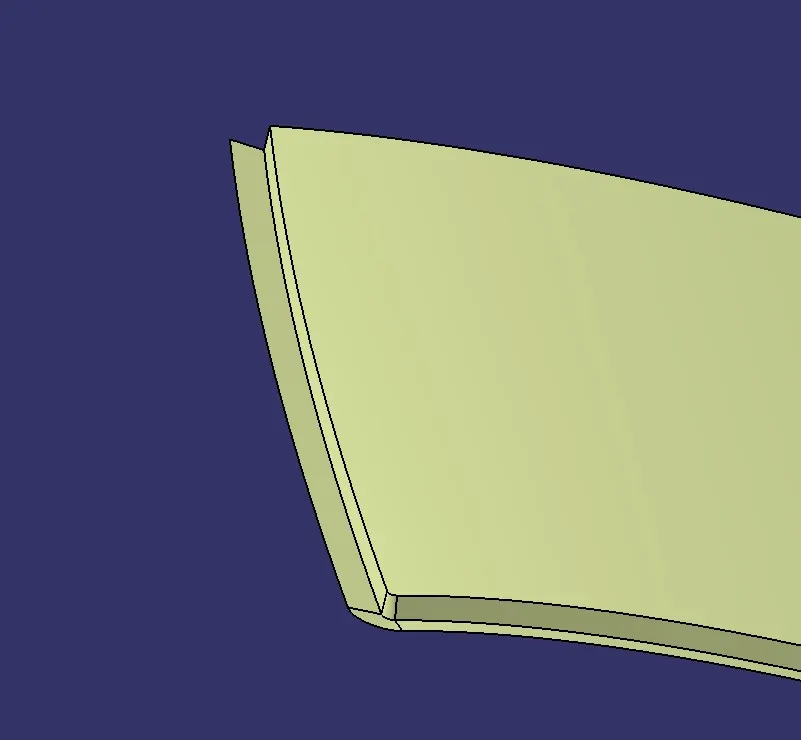
As same as for the rear flange also create the flange with consideration of the given master section image below.
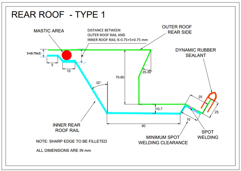
We have to check there is no sharp edge.
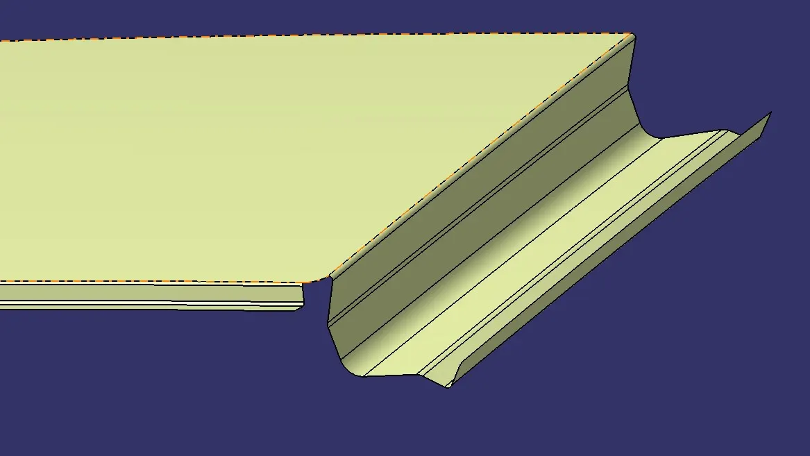
After making the rear and front flange give all the required fillets at the sharp edges and do a symmetry with the mid plane.image mention below.
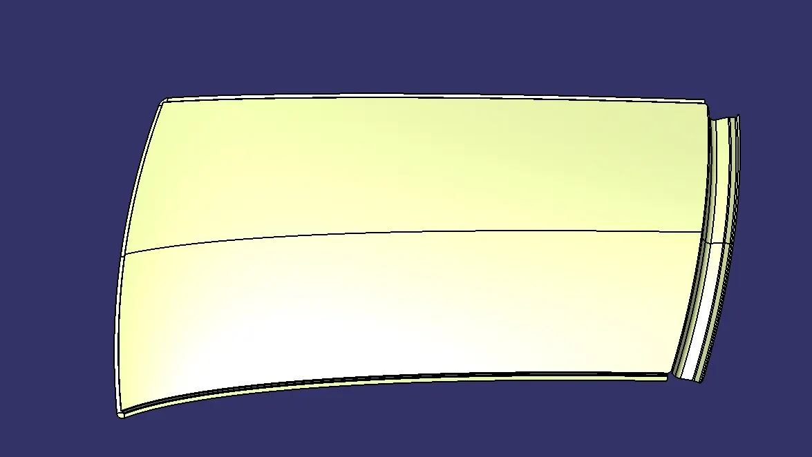
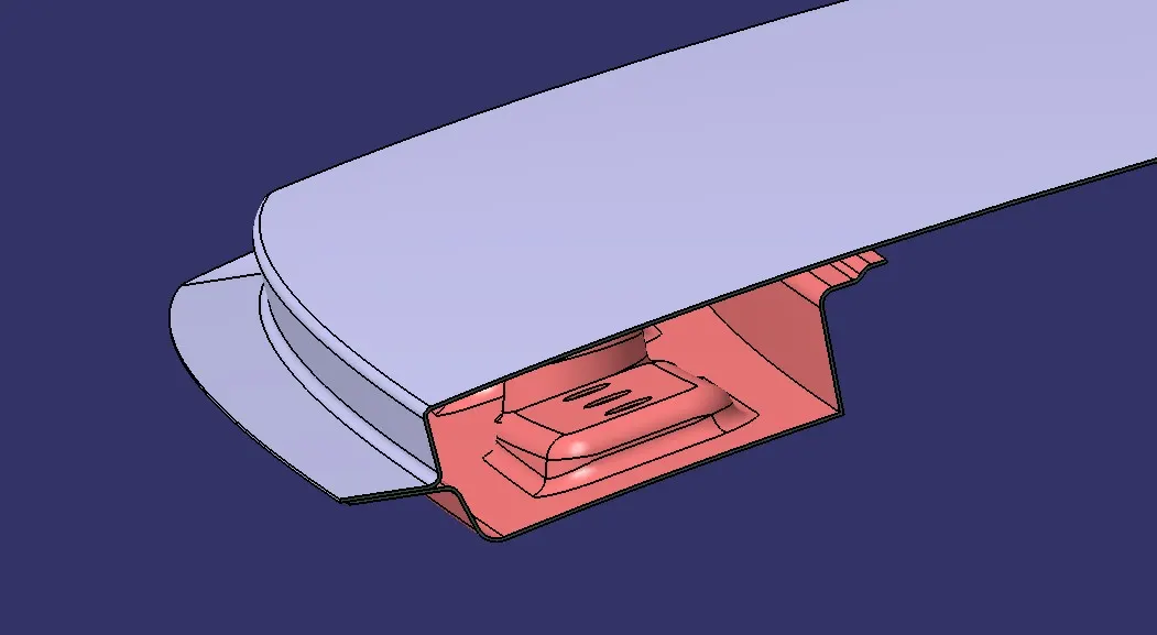
Next move on to the Front roof rail with the consideration of the master section
Design Procedure of Front Roof Inner Panel:
- Offset the roof to 2.7mm and split it with a distance of 5mm.
- Similarly, create an offset of 4.7mm and cut it.
- create an offset of 6.5mm and cut it.
- Now create a base offset of 32mm from the roof.
- Create the respective sweeps for these offsets and trim them together.
- Give the Edge fillets to it.
- After that embosses are created on this to provide more strength.
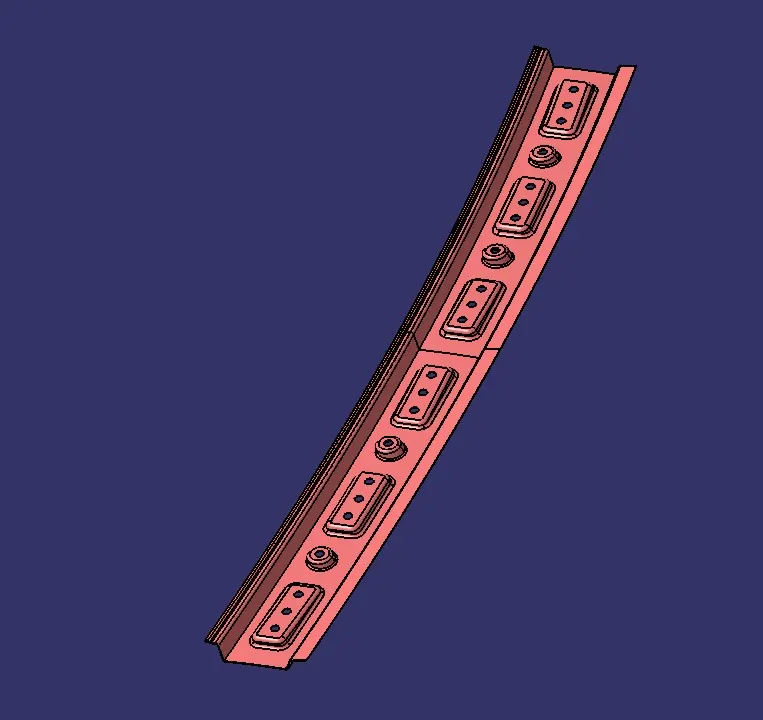
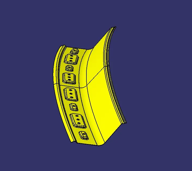
Design Procedure of Rear Roof inner Panel:
- For the rear roof, rail follows a similar procedure as the front roof and the values for it are given in the master section.
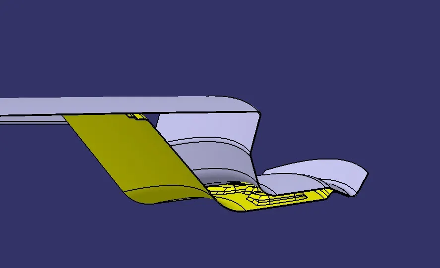
- Make sure that the Rear roof has a positive draft angle.
- After that embossed & slots are created on this to provide more strength and reduce the weight of the BIW component. image mention below.
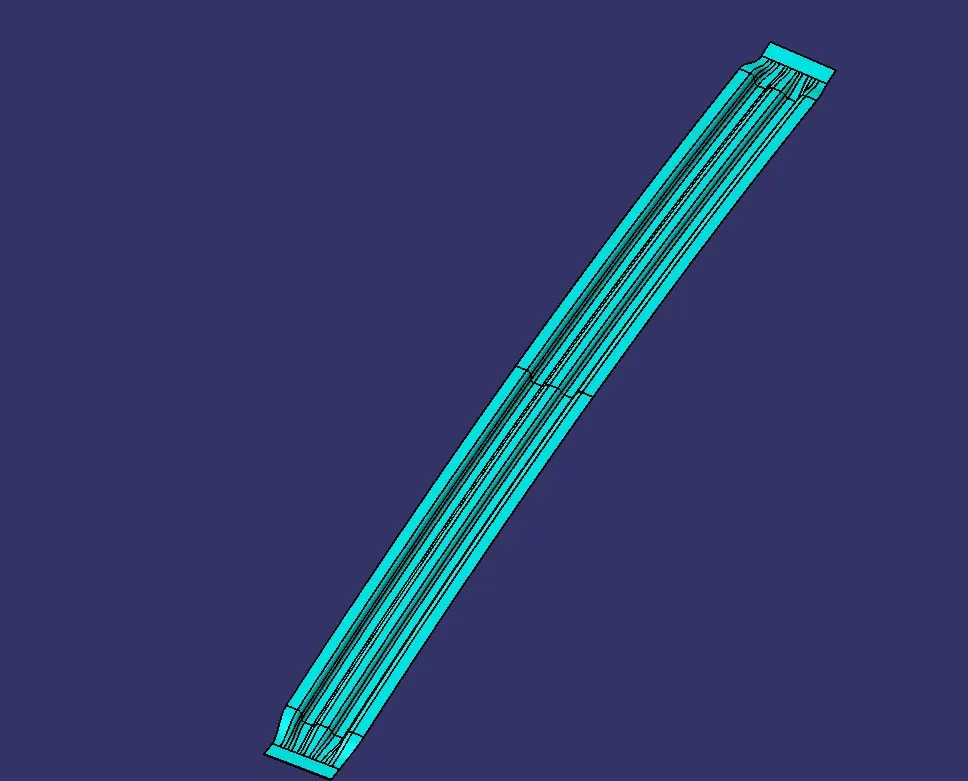
Creating the Centre Roof Rail:
- The Centre Roof Rail has attached at the center of the roof.
- To create the center Roof Rail as per the master section.
- Now create the part as per the design standards and make sure that the offset is given considering the thickness of the component.
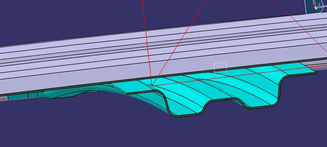
- ditch area needs to be created so that the reinforcement is attached to the roof flange.
- To create that area, select the flange and create an offset to the length including the thickness of the roof and the connecting parts.
- Cut the Offset to the length which is less than the width of the center reinforcement.
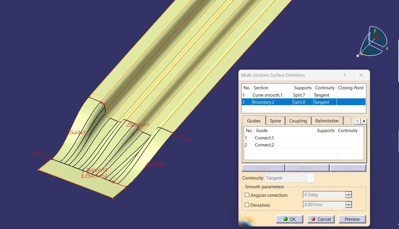
- Create Splines on both edges of the surface.Use the Multi-section surface option to select the edges and the curves created as the guide curves to create a body.
Join the surfaces together. image mention below.
Creating the Bow roofs:
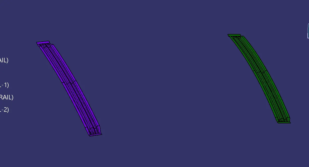
- Two bow roofs are created to give strength to the roof.
- Follow the same method as with the center roof rail to create the bow roof.
- Now, after the bow roof is created. The Flanges for the mastic points need to be created.
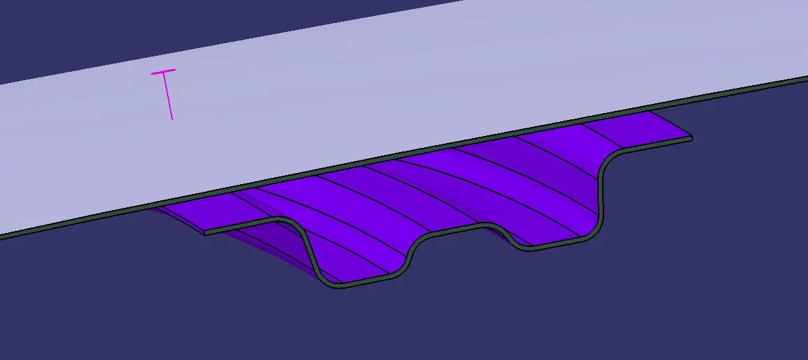
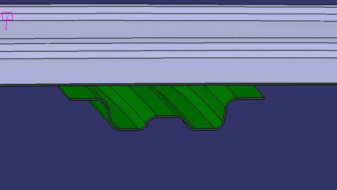
After Creating the surfaces, use the thicken option to create the solids with the proper thickness.
The thickness for the Roof And all other parts is Considered 0.75mm. image mention below.
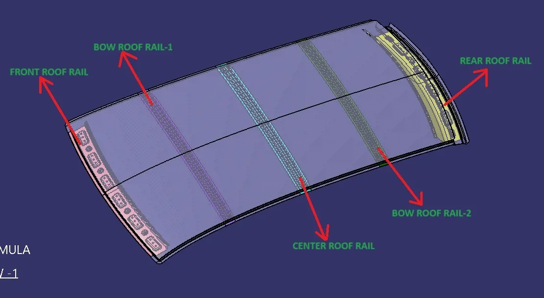
Bow roof prediction calculation:
Heat Distortion Criteria:
Heat distortion temperature is the temperature at which the metal softens and deforms under a specific load.
This study is done to check the ability of the roof to withstand high temperature with respect to the positioning of the reinforcements which contribute to increased strength.
The use of high-tensile steel sheets on car bodies has increased, and the weight of bodies has decreased, for enhance fuel economy.
by fabricating pieces from thinner sheets. The surface areas of outer panels such as a roof panel and door outers are large, so the effects of weight reduction are also large and thereby the needs for thinner panels are high.
Some studies have noted issues with the outside quality where, when thinner outer panels are employed, the surfaces of shells bend owing to thermal strain during the painting and drying processes in addition to issues with the stamping performance (hence, referred to as thermal distortion).
The washing, electrodeposition, sealing, and finish coating steps are all included in the painting of a vehicle's body. An automobile body is submerged in an electrocoating solution during the electrodeposition process to create an electrodeposited film.
The body is then put through the drying process, where hot air from a furnace is used to dry the electrocoating solution. If thermal distortion is discovered, it requires a significant amount of labour -hours for reworking and checks for numerous parts and across multiple manufacturing processes.
Thermal distortion is frequently evaluated by the exterior check conducted for completed vehicles with various parts installed.
W = [1.73 x 10^(-3) x L] + [1.85 x 10^(-8) x (R^2)/t] + [ 1.10x10^(-3) x l] - 2.68
Judgement Condition : OK< 2.7> 3.1
Where
L = Roof Length in X-Direction[mm](Roof dimension in 0-Y)
R = Roof curvature
R = 2(Rx*Ry)/(Rx+Ry)
Rx = X curvature
Ry = Y curvature
t = Roof plate thickness [mm]
l = Bow Roof Span [mm]
Judgment Condition
OK< 2.7
To create the sketch for Checking the Heat Distortion criteria:
- To calculate the Heat distortion criteria, we have to take note of a few values and note it down.
- To note down, first, we need to create a sketch.
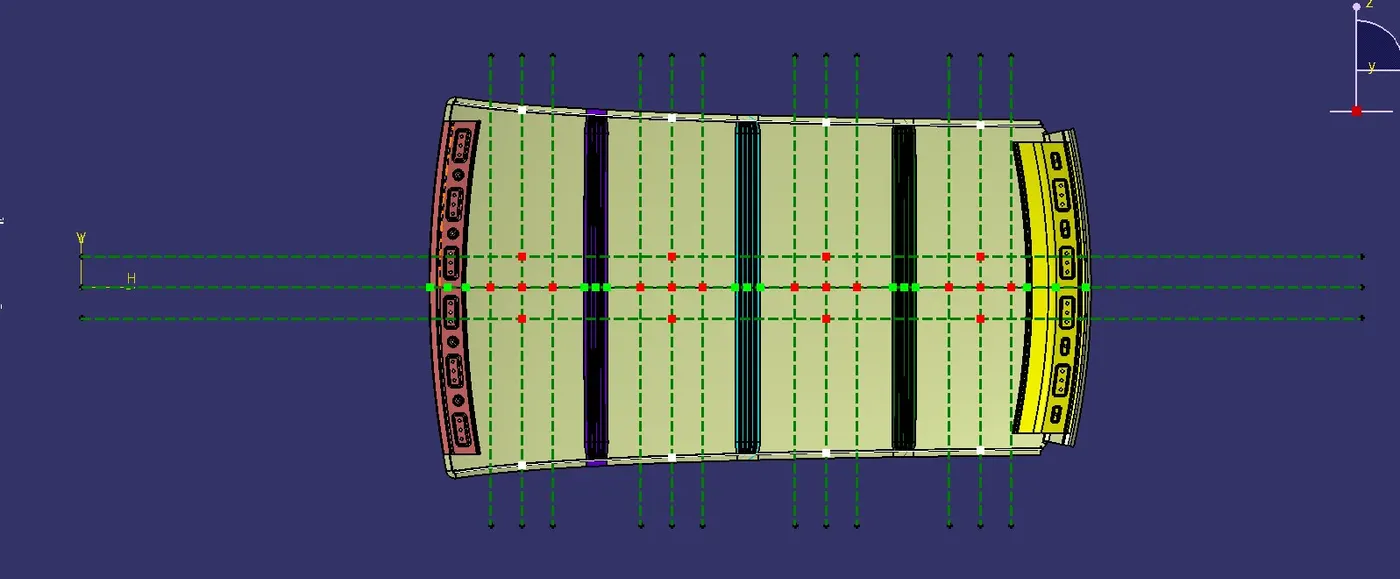
- Create a line at the center of the roof part in the 0-Y axis and then draw another line with a distance of 300mm.
- Now create the line with a distance of 100 on both sides at the line which is at 300mm.
- Now create the line between the rails in the X direction and create 2 lines with a distance of 100mm on both sides.
- Now create a point coinciding with both lines.
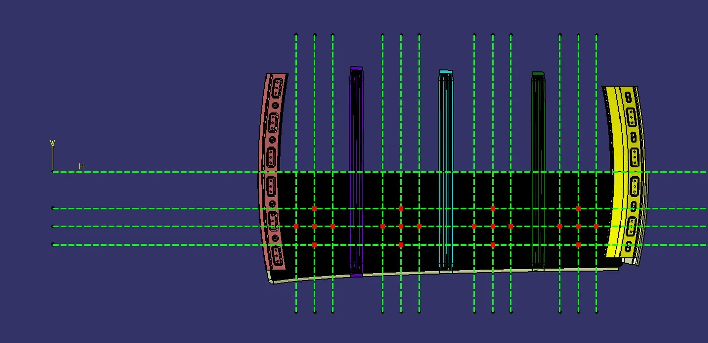
Finish the sketch and project the points shown on the upper surface of the roof outer surface.
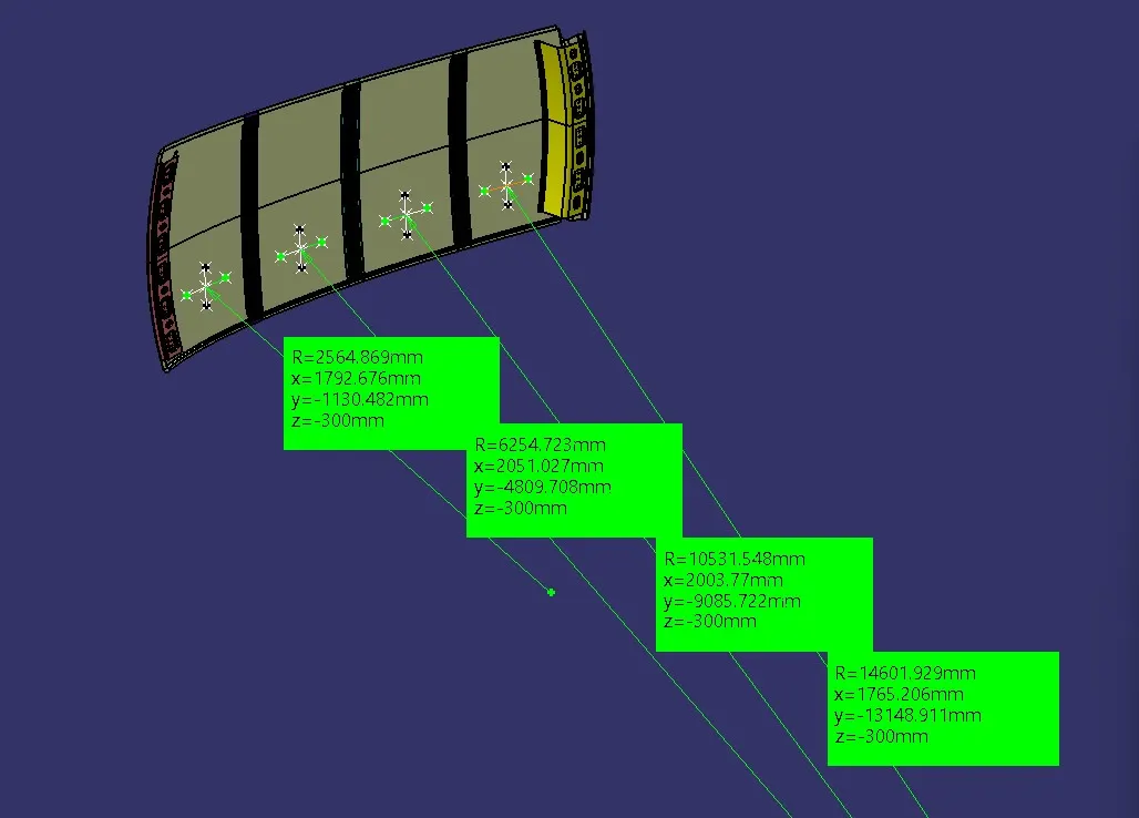
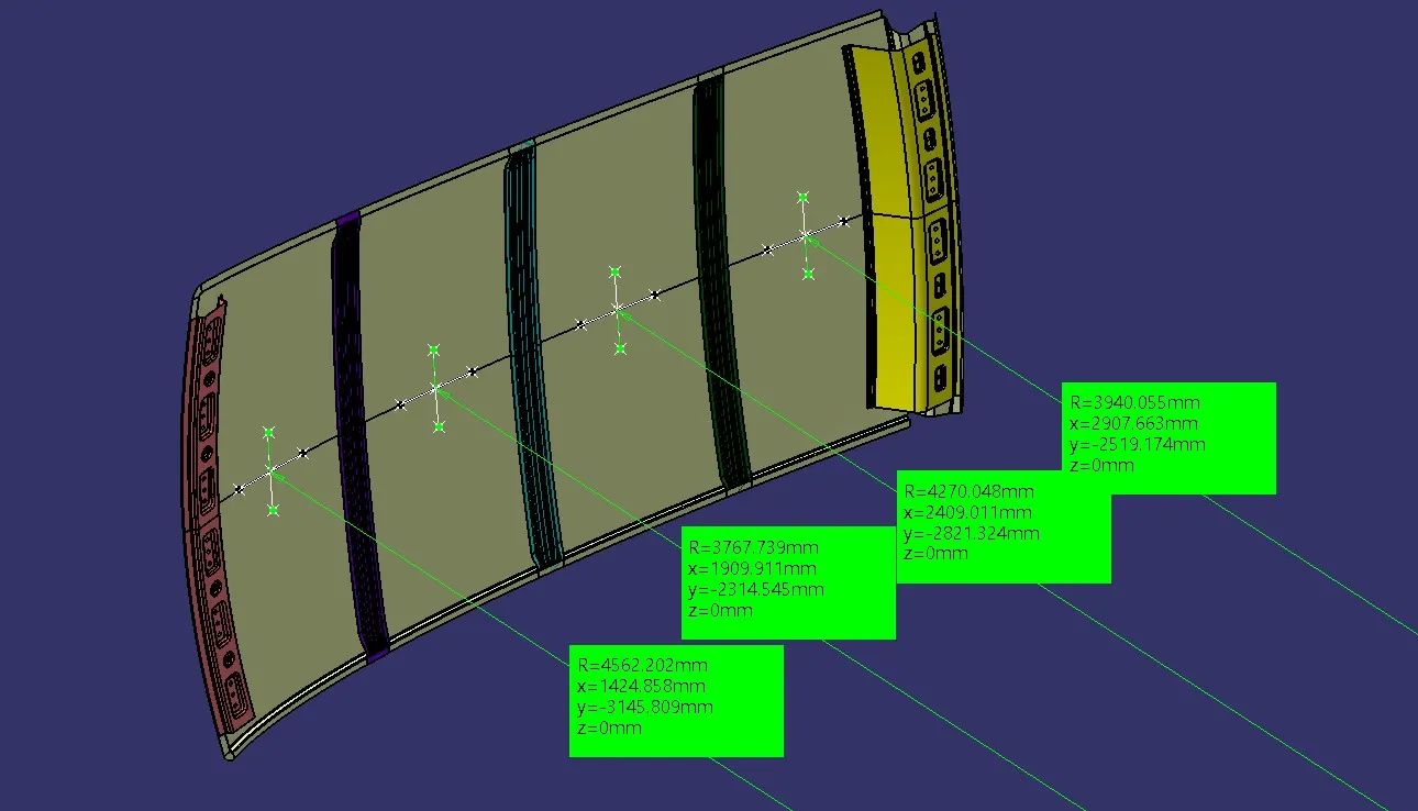
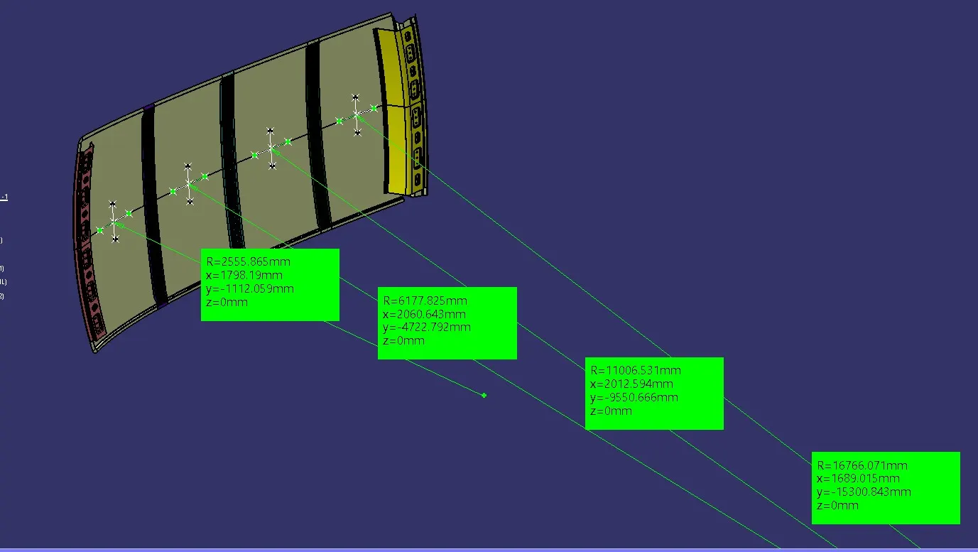
Take the three-point command option by specification start point, end point and mid-point. This operation you have to continue with all the horizontal and vertical points you petted. To display the radius of the created arc (Rx-Ry), the local radius command is used.
FOR Rx
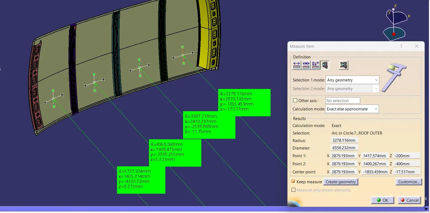
FOR Ry
I’m Calculating the Heat Distortion Criteria by using excel calculator by giving the formula:

If the value of W is satisfying this condition OK< 2.7 then it’s represented by OK. It’s Means Roof Fulfilling the conditions of Heat Distortion Criteria.
Or If the value of W is not satisfying this condition OK< 2.7 then it’s represented by NOT OK. This means the Roof not Fulfilling the conditions of Heat Distortion Criteria. So, we need to change the design of the bow roofs.
SNOW LOAD PREDICTION:
Snow Load Criteria study is done to check the withstand ability when the snow loads over the roof during winter in snow fall regions. This study will also analyse the roof that whether the permanent deformation occurs after removing the snow load. That it may bend but needs to be bounce back to its original position.
roof design must pass through these calculations to ensure that it has sufficient stiffness to withstand the load due to accumulation of snow over the roof.
Similar steps we have to repeat to find your R-x and R-y for snow load calculation but we have to do all these operations with zero 0-Y line.
Qr = [Iy x t2] / [α x s x [(Rx + Ry)/2]2 x 10-8]
Where,
α = My x Lx2 x 10-12 , My = Y(Ly-Y)
t = Roof plate thickness [mm]
Ly = Distance between the front and rear roof Rails on the Vehicle along with 0Y[mm]
Length of Roof panel with the center point between Roof rail Front /Rear as the front and rear reference point.
Lx = Distance between the Left and Right end of the roof on the Roof BOW [mm]
The width of the roof panel is exposed on the surface.
Y = Distance front Front Roof Rail to Roof BOW[mm]
s = Distance for which Roof BOW bears divided load [mm]
s = L1/2 + L2/2
Iy = Geometrical moment of inertia of Roof BOW (Y cross-section )[mm4]
Rx = Lateral direction curvature radius of roof panel Y cross-section on Roof BOW [mm]
Roof panel curvature Radius of the Length Lx in Front view
Ry = Longitudinal Direction curvature radius of the Roof panel X cross-section on Roof BOW [mm]
Roof panel X curvature radius of length s in Side view
Judgment condition
Qr ≥ 3.1
To create the sketch for Checking the Snow Load Criteria:
- To calculate the Snow Load criteria, we have to take note of a few values and note it down.
- To note down, first, we need to create a sketch.
- Create a line at the center of the roof part in the 0-Y axis
- Now create the line with a distance of 100 on both sides.
- Now create the line between the rails in the X direction and create 2 lines with a distance of 100mm on both sides.
- Now create a point coinciding with both lines.
- Extract the points to the roof and create the arc using 3 points by creating two lines intersecting with each other.
- Measure the radius of the arc in the Y direction as Ry, Ry, and X direction as Rx, Rx.
Rx VALUE:
Ry VALUE:
MOMENTUM OF INERTIA :
The area moment of inertia is a property of a two-dimensional plane shape that characterizes its deflection under loading. It is also known as the second moment of area or second moment of inertia. The area moment of inertia has dimensions of length to the fourth power.
- To check the section inertia, we need to create the intersection in the Y-axis.
- After the intersection is done, fill the surface with the intersection created.
- Select the Measure Inertia option to measure the 2D inertia of the surface created.
- Note down the values.
BOW ROOF RAIL-1:
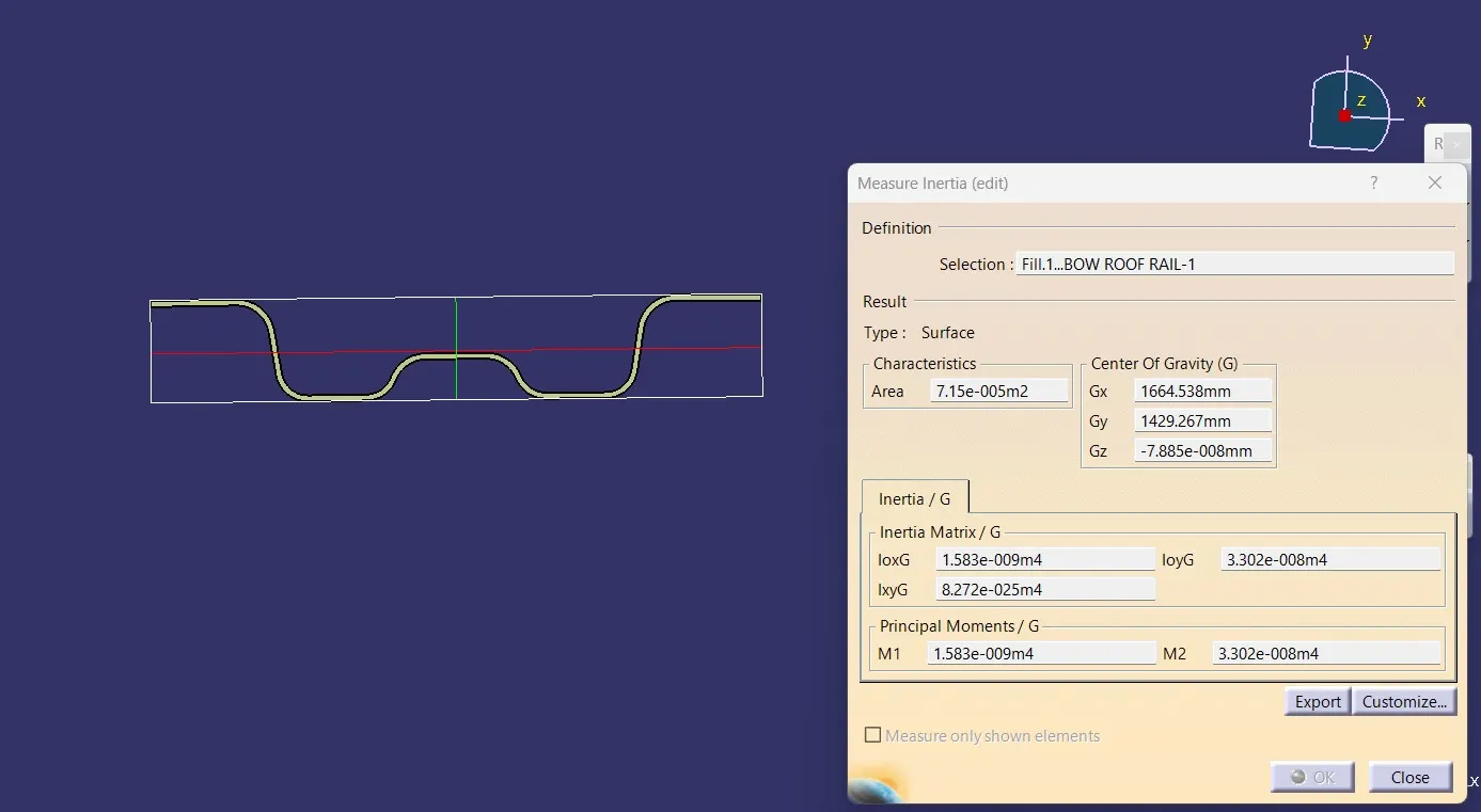
M1=1.583 x 10^-9 m^4
Iy=1.583 x 10^3 mm^4
Iy=1.583 mm^4
CENTER ROOF RAIL:
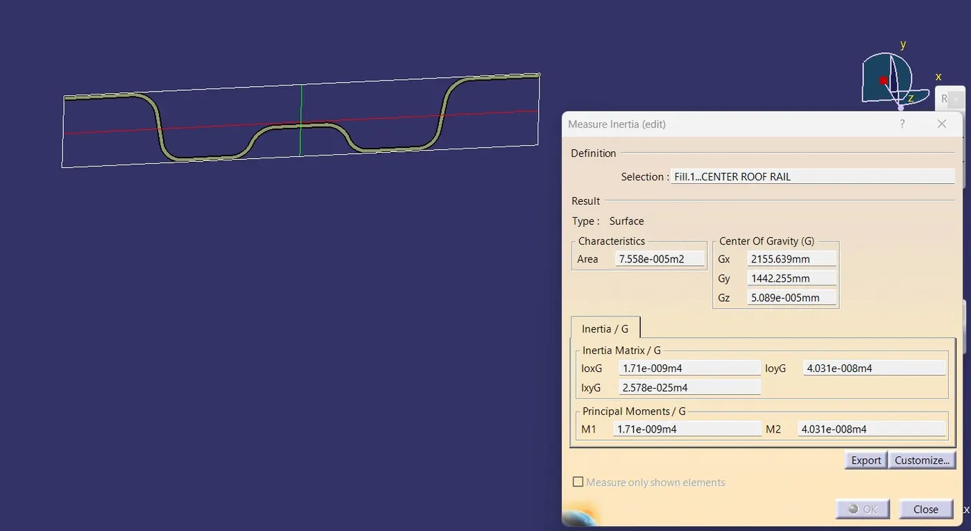
M1=1.710 x 10^-9 m^4
Iy=1.710 x 10^3 mm^4
Iy=1.710 mm^4
BOW ROOF RAIL-2:
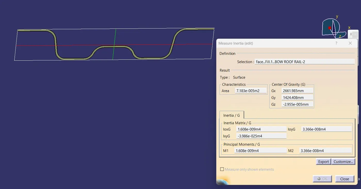
M1=1.608 x 10^-9 m^4
Iy=1.608 x 10^3 mm^4
Iy=1.608 mm^4.
I’m Calculating the Snow Load Criteria by using an excel calculator by giving the formula:

If the value of Qr is satisfying this condition of Qr ≥ 3.1 then it’s represented by OK. It’s Means Roof Fulfilling the conditions of Snow Load Criteria.
If the Qr value doesn't lie say the styling team to create some embosses on the outer panel.
DRAFT ANALYSIS:
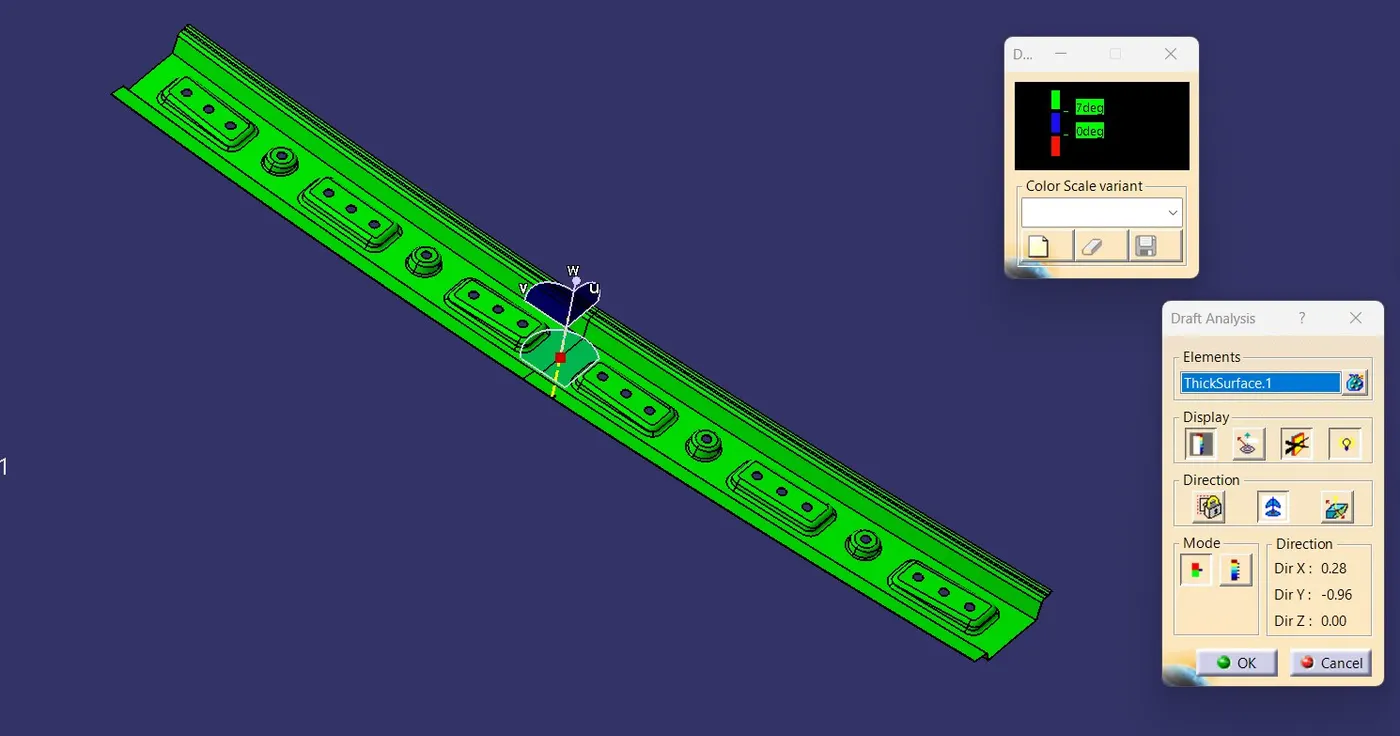
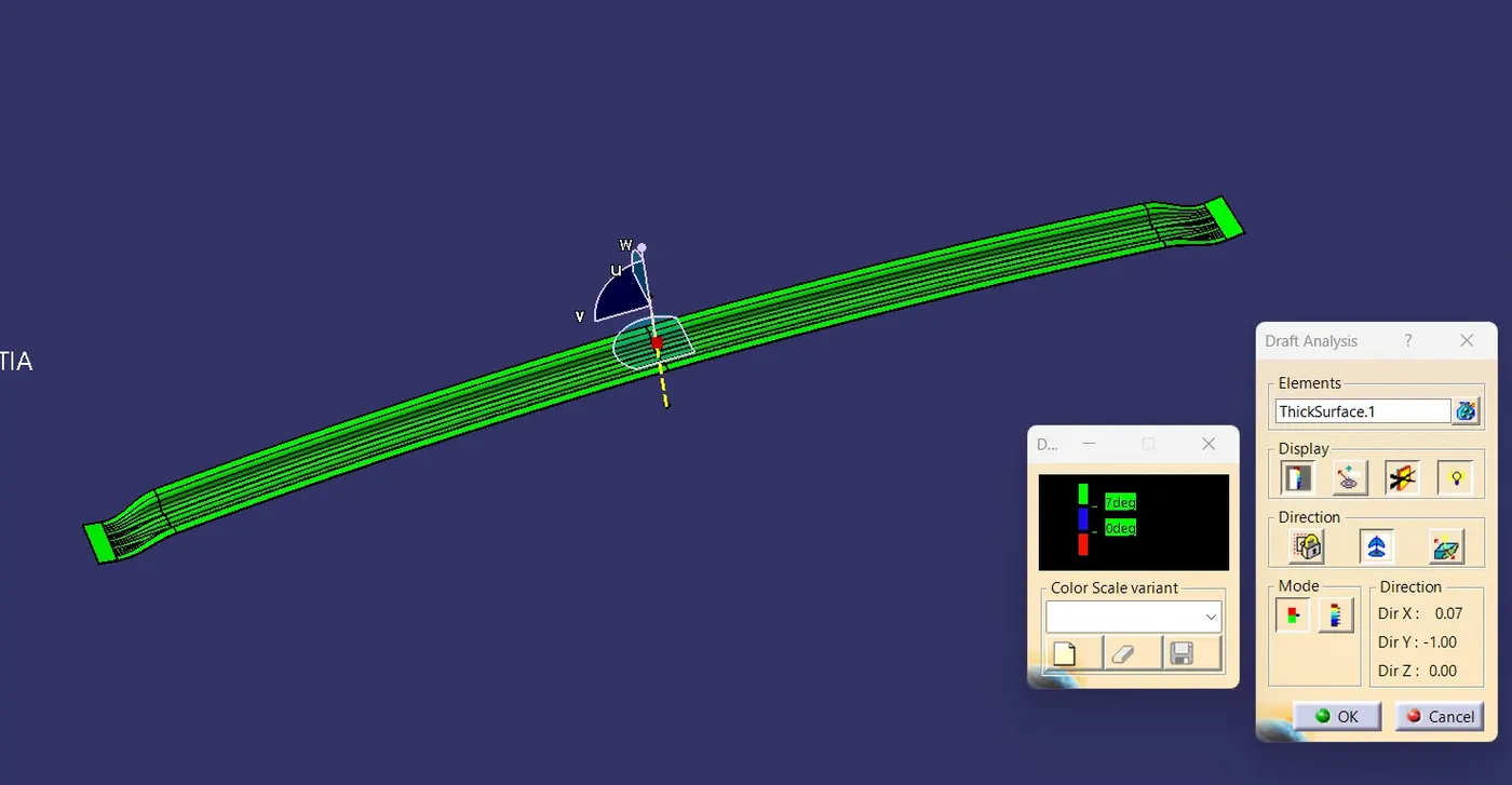
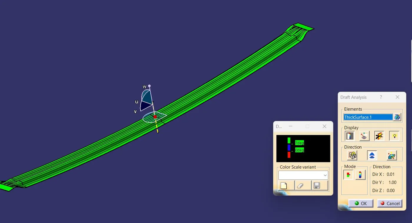
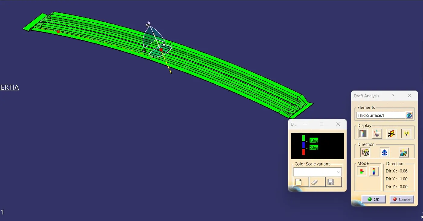
Draft analysis is a method of checking the draft angle on various faces of a part with a particular direction. it should be Minimum 7 deg of draft angle
OUTER ROOF PANEL:
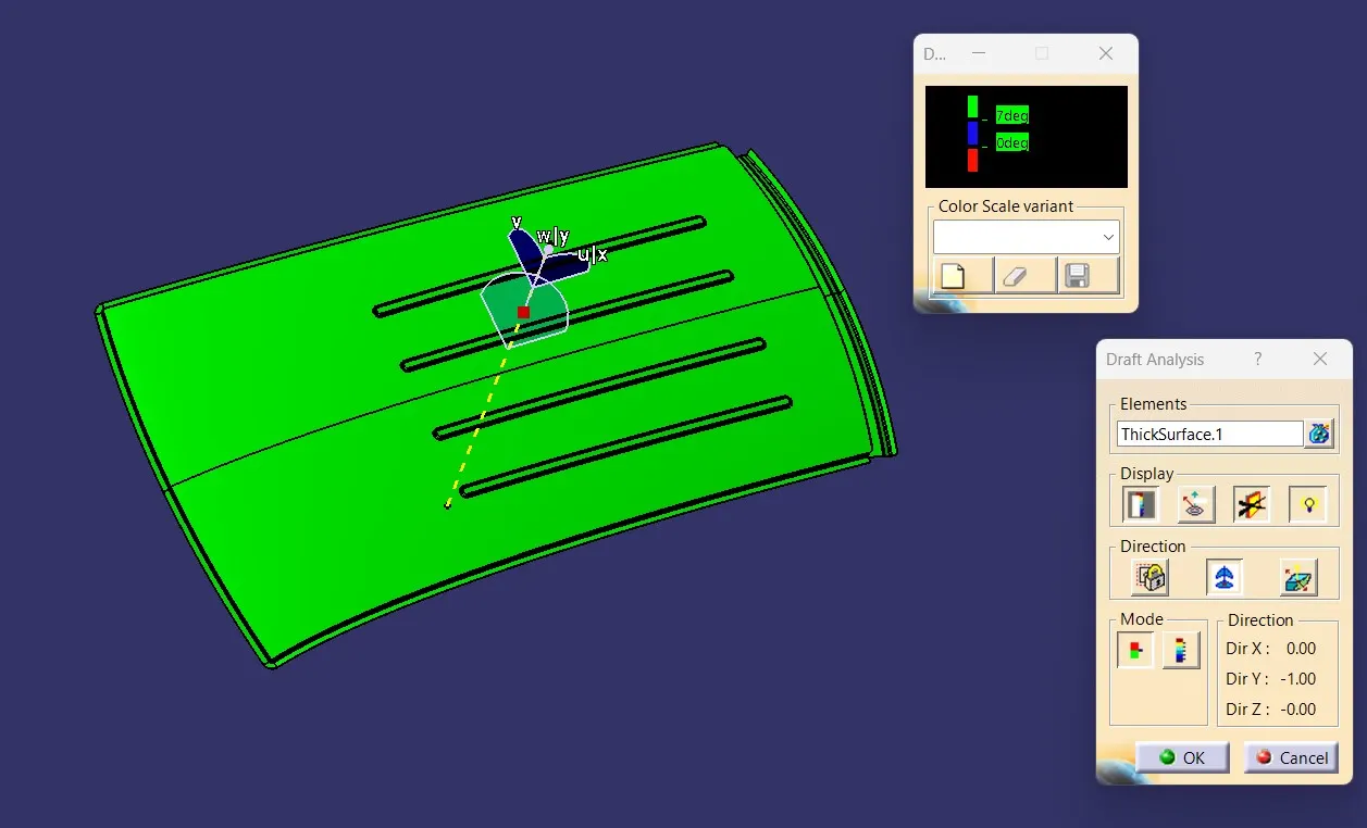
FRONT ROOF RAIL:
BOW ROOF RAIL-1:
CENTER ROOF RAIL:
BOW ROOF RAIL-2:
REAR ROOF RAIL:
FINAL PRODUCT:
CONCLUSION:
We design and develop the Roof of a car with its components like front roof rail, bow roof rails, center roof rail, rear roof rail by following the given master section and design parameters.And did curvature study and analysis of the design for heat distortion and snow load criteria and Moment of inertia and draft analysis is carried out to check the feasibility of manufacturing are good.