Roof Design
DESIGN AND DEVELOPMENT OF CAR ROOF AND ITS REINFORCEMENTS
Objective:
The main objective of this project is to develop the car roof design and its reinforcements from the given styling surface. And to prepare a detailed report about the engineering standards for roof design, its design procedure, analysis and manufacturing techniques.
Description:
Introduction:
An automobile roof or car top is the portion of an automobile that sits above the passenger compartment, protecting the vehicle occupants from sun, wind, rain, and other external elements. Because the earliest automobiles were designed in an era of horse-drawn carriages, early automobile roofs used similar materials and designs.
Design parameters:
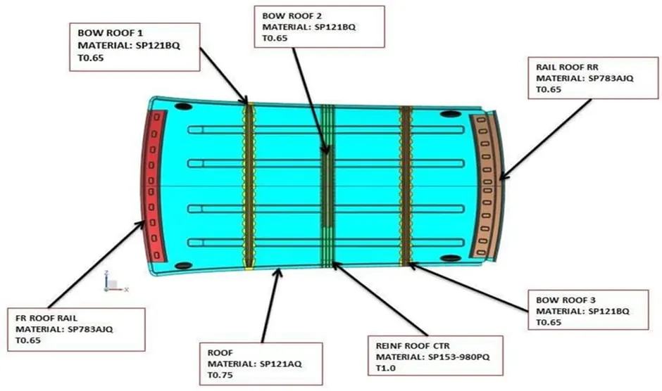
The styling surface of a hardtop roof is given by the styling team to develop it. Commonly the car roof consists of outer panel and its reinforcements. Those reinforcements are,
1.Front roof rail
2.Bow roof
3.Centre roof and
4.Rear roof rail.
5.Rear roof rail
There are certain engineering standards to design the automobile roof. These standards are derived from trial and error method to reduce the material wastage, production cost and to improve the safety over the years. These standards may vary region to region according to the conditions, usage, rules and regulations of that particular region.
The common considerations for roof design are head room clearance, driving vision, heat distortion criteria and snow load criteria.
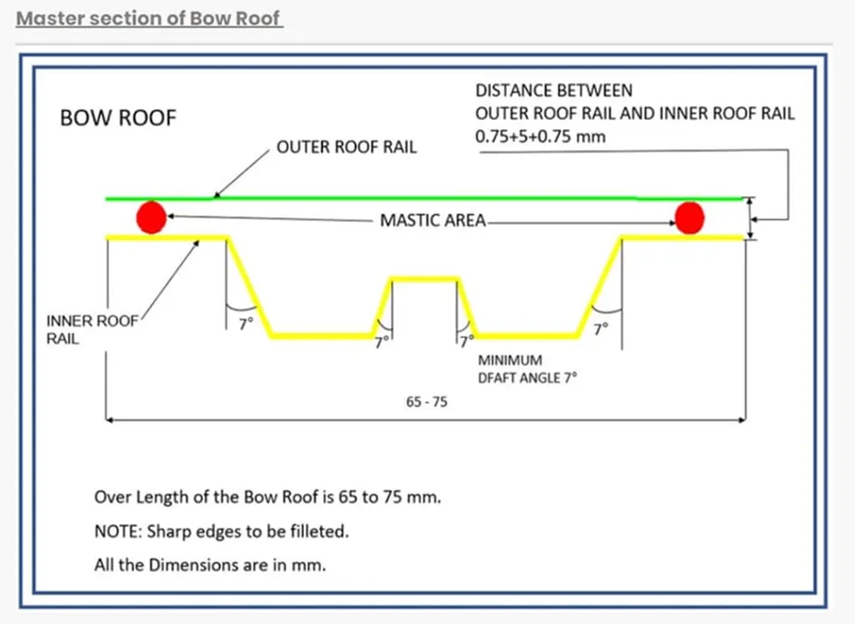
The common standards for car roof design where the draft angle should be minimum of 7º and the blends should be minimum of 3+t (t-thickness of the part).
Master section:
Master sections are the 2D outlines which is taken at a particular area of a 3D model or it is an intersection of 3D model about a reference plane to study its outline (or boundary) in a 2D view. These master sections are widely used in OEMs and in automotive industries to convey the functional requirements of commodity to the design engineer.
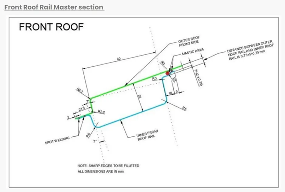
It gives the parameters like length, width, height, radius and clearance should be considered while designing the particular part or component. For this project it gives the parameters to be considered while designing the roof outer panel, front roof rail, bow roof, centre roof and rear roof rail.
1.Roof outer panel and front roof rail master section
Design procedure:
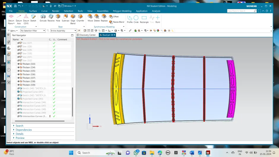
In this project, design and development of car roof starts from creation of an assembly file and inserting the styling surface to the assembly window. By using this method, assembly of roof and its reinforcements become very easy and the reinforcements of roof were created at the part level individually. The main parts of car roof consist of,
Roof outer panel
Front roof rail
Bow roof-1
Centre roof rail
Bow roof-2 and
Rear roof rail.
Roof outer panel:
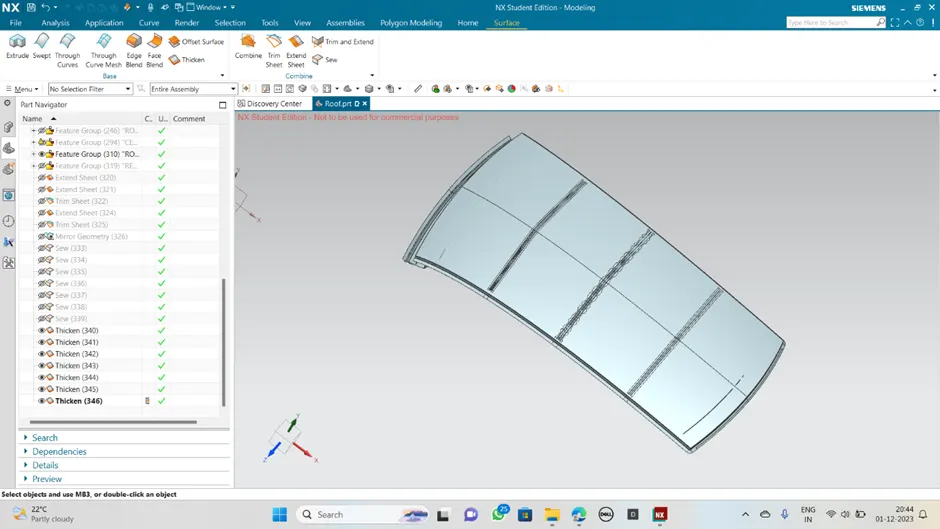
The whole car roof is made of sheet metal, so it is called as BIW. The roof outer panel is the aesthetic part of the roof and also it is the external part which covers the occupant or passenger compartment from the wind shield to the back door.
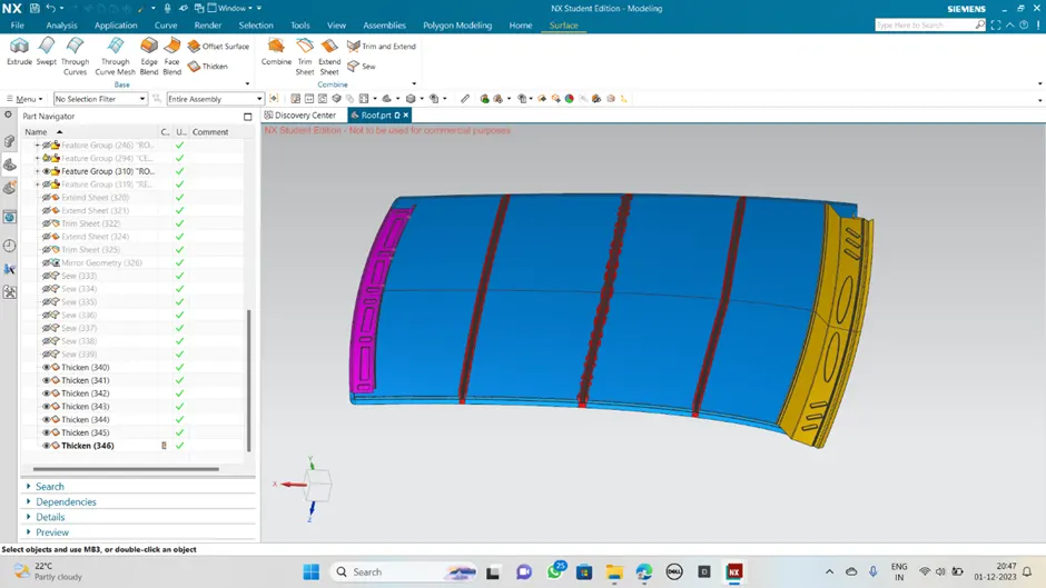
<!-- [if !supportLists]-->· <!--[endif]-->The given styling surface is extracted to start the development of roof and the styling surface is kept untouched for future reference as an input surface.
<!-- [if !supportLists]-->· <!--[endif]-->The extracted surface is then untrimmed to fill the gaps and holes in it, then trim command was applied to remove the extra surfaces over the boundaries of styling surface.
<!-- [if !supportLists]-->· <!--[endif]-->With respect to the master section of front roof rail, the law extensions of flange is created at the front side.
<!-- [if !supportLists]-->· <!--[endif]-->Then these extensions were sewed to apply edge blends to its edges and corners.
<!-- [if !supportLists]-->· <!--[endif]-->After creating the front flange, the ditch area was created using the same law extension, sew and edge blends with respect to the dimensions used for the front flange.
<!-- [if !supportLists]-->· <!--[endif]-->The corner gap between the front flange and the ditch area is filled using the bride curves and through curve mesh commands to have a smoother corner.
<!-- [if !supportLists]-->· <!--[endif]-->Then, with respect to the rear roof rail master section, rear flange of the outer panel was created following the previous steps and here the corners were left untouched to give some reliefs, but the sharp corners were trimmed off.
<!-- [if !supportLists]-->· <!--[endif]-->After this the sheet is extended at the 0y section and trimmed with xz plane to avoid gaps while mirroring it.
<!-- [if !supportLists]-->· <!--[endif]-->The completed outer panel is mirrored about the respective plane and sewed them together.
<!-- [if !supportLists]-->· <!--[endif]-->Finally, the whole outer panel surface was thickened to 0.75mm to form a solid part and its sharp edges were blended.
Front roof rail:
Front roof rail is one of the reinforcements of roof which is present at the front and provides required strength to the roof.
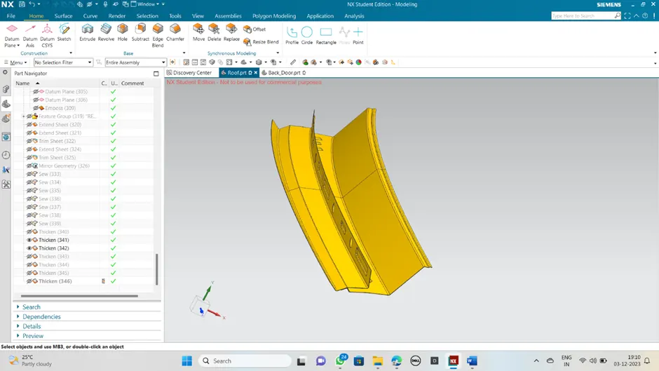
<!-- [if !supportLists]-->· <!--[endif]-->The reference surfaces for front roof are taken from the roof outer panel using the wave geometry linker command. And their links were broken and kept as the input surfaces for front roof rail.
<!-- [if !supportLists]-->· <!--[endif]-->With help of these surfaces, the front roof rail creation starts by offsetting it to the required dimensions according to front roof rail master section.
<!-- [if !supportLists]-->· <!--[endif]-->After the offsets, using the ‘offset curve in face’ command, required curve was offset to the required positions to remove the unwanted surfaces.
Bow roof-1:
Bow roof is one of the reinforcements of roof which is present at the flat regions of roof to with stand heat distortion and snow load conditions. By using the bow roofs permanent deformation of roof at the flatter region is avoided by stress distribution.
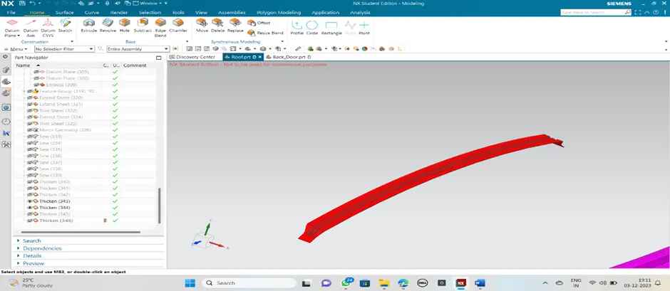
<!-- [if !supportLists]-->· <!--[endif]-->The reference surfaces for bow roof are taken from the roof outer panel using the wave geometry linker command. And their links were broken and kept as the input surfaces for bow roof.
<!-- [if !supportLists]-->· <!--[endif]-->With help of these surfaces, the bow roof creation starts by offsetting it to the required dimensions according to bow roof master section.
<!-- [if !supportLists]-->· <!--[endif]-->After the offsets, using the ‘offset curve in face’ command, required curve was offset to the required positions to remove the unwanted surfaces.
<!-- [if !supportLists]-->· <!--[endif]-->Those unwanted surface were removed using the ‘trim sheet’ command and the surfaces in different heights were connected using the ‘through curve’ command.
<!-- [if !supportLists]-->· <!--[endif]-->Now, these surfaces are sewed together using ‘sew’ command and then its corners are blended using the ‘edge blend’ command.
<!-- [if !supportLists]-->· <!--[endif]-->Then mastic regions were created at the outer flanges of bow roof using the sketch created on the plane normal to the surface by projecting it to the surface and trimming the unwanted regions.
<!-- [if !supportLists]-->· <!--[endif]-->Once, the surface creations were done, then the sheet is extended and trimmed at 0y region.
Finally, the bow roof surface is mirrored about the xz plane, then sewed them together using ‘sew’ command to thicken it using ‘thicken’ command to create a solid part and its sharp edges were blended.
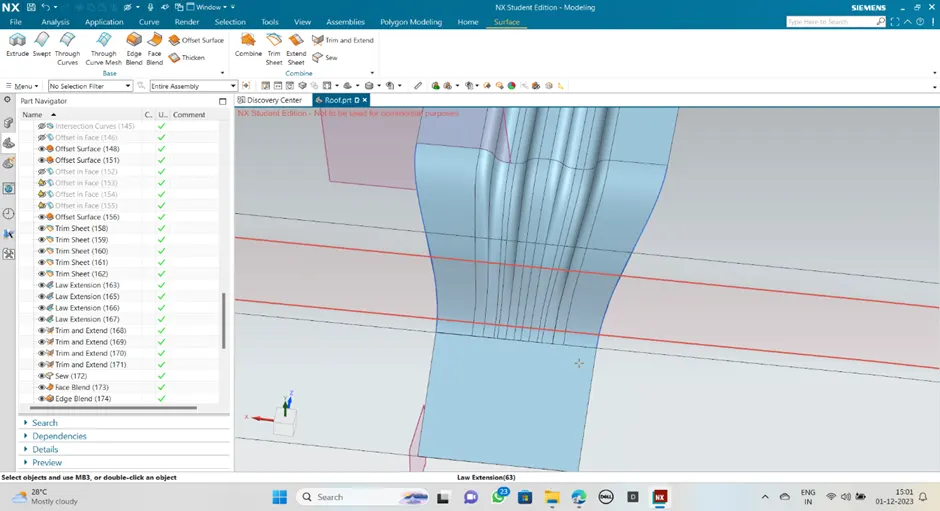
Those unwanted surface were removed using the ‘trim sheet’ command and the law extensions were created to connect the surfaces in different heights.
Now, the overlapping surfaces were trimmed with ‘trim and extend’ command to make corners, then these corners are blended using the ‘edge blend’ command.
<!-- [if !supportLists]-->· <!--[endif]-->Then some embosses were created, to improve the strength of front roof rail using the ‘emboss’ command.
<!-- [if !supportLists]-->· <!--[endif]-->Once, the surface creations were done, then the sheet is extended and trimmed at 0y region.
<!-- [if !supportLists]-->· <!--[endif]-->Finally, the front roof rail surface is mirrored about the xz plane, then sewed them together using ‘sew’ command to thicken it using ‘thicken’ command to create a solid part and its sharp edges were blended.
Centre roof rail:
Centre roof rail is one of the reinforcements of roof which is present at the centre region of roof or at the region where the B-pillar connects with the roof.
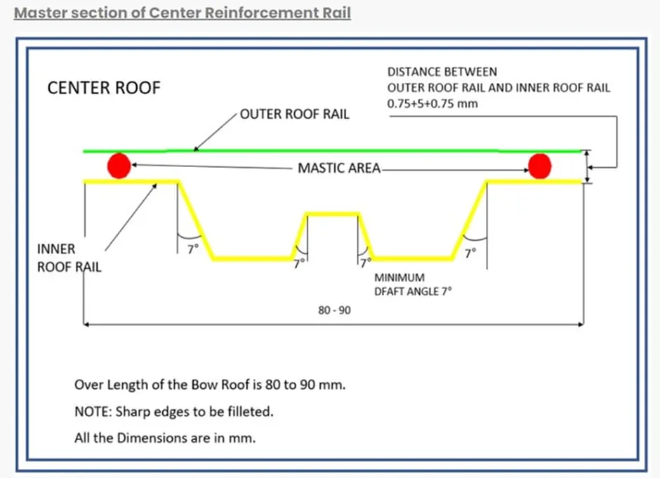
<!-- [if !supportLists]-->· <!--[endif]-->The reference surfaces for centre roof rail are taken from the roof outer panel using the wave geometry linker command. And their links were broken and kept as the input surfaces for centre roof rail.
<!-- [if !supportLists]-->· <!--[endif]-->With help of these surfaces, the centre roof rail creation starts by offsetting it to the required dimensions according to centre roof rail master section.
<!-- [if !supportLists]-->· <!--[endif]-->After the offsets, using the ‘offset curve in face’ command, required curve was offset to the required positions to remove the unwanted surfaces.
<!-- [if !supportLists]-->· <!--[endif]-->Those unwanted surface were removed using the ‘trim sheet’ command and the surfaces in different heights were connected using the ‘through curve’ command.
<!-- [if !supportLists]-->· <!--[endif]-->Now, these surfaces are sewed together using ‘sew’ command and then its corners are blended using the ‘edge blend’ command.
<!-- [if !supportLists]-->· <!--[endif]-->Then mastic regions were created at the outer flanges of bow roof using the curves which is created by ‘curve on surface’ command and with help of these curves, the unwanted regions were trimmed off.
Once, the surface creations were done, then the sheet is extended and trimmed at 0y region.
Finally, the bow roof surface is mirrored about the xz plane, then sewed them together using ‘sew’ command to thicken it using ‘thicken’ command to create a solid part and its sharp edges were blended.
Rear roof rail:
Rear roof rail is one of the reinforcements of roof which is present at the rear and provides required strength to the roof at rear side.
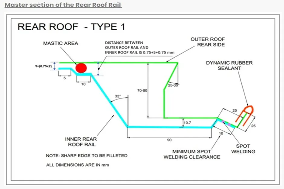
<!-- [if !supportLists]-->· <!--[endif]-->The reference surfaces for rear roof are taken from the roof outer panel using the wave geometry linker command. And their links were broken and kept as the input surfaces for rear roof rail.
<!-- [if !supportLists]-->· <!--[endif]-->With help of these surfaces, the rear roof rail creation starts by offsetting it to the required dimensions according to rear roof rail master section.
<!-- [if !supportLists]-->· <!--[endif]-->After the offsets, using the ‘offset curve in face’ command, required curve was offset to the required positions to remove the unwanted surfaces.
<!-- [if !supportLists]-->· <!--[endif]-->Those unwanted surface were removed using the ‘trim sheet’ command and the law extensions were created to connect the surfaces in different heights.
<!-- [if !supportLists]-->· <!--[endif]-->Now, the overlapping surfaces were trimmed with ‘trim and extend’ command to make corners, then these corners are blended using the ‘edge blend’ command.
<!-- [if !supportLists]-->· <!--[endif]-->Then some embosses were created, to improve the strength of rear roof rail using the ‘emboss’ command.
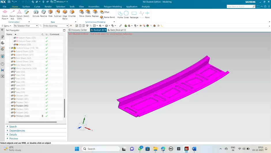
Once, the surface creations were done, then the sheet is extended and trimmed at 0y region.
Finally, the rear roof rail surface is mirrored about the xz plane, then sewed them together using ‘sew’ command to thicken it using ‘thicken’ command to create a solid part and its sharp edges were blended.
Analysis:
For this project the following analysis were done to check the tooling feasibility, strength and rigidity of the roof to avoid the errors in early stages itself.
Draft analysis:
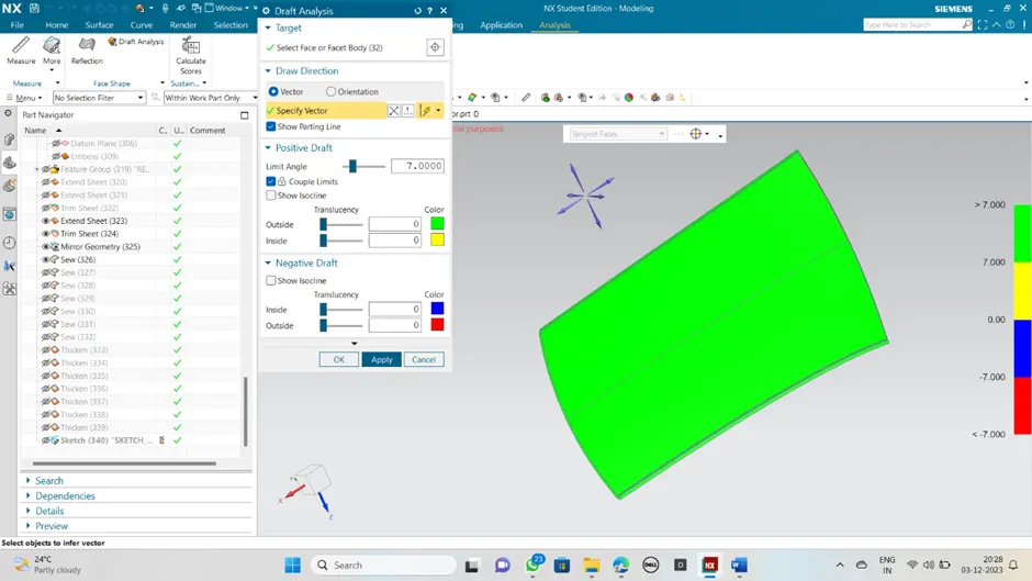
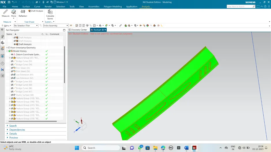
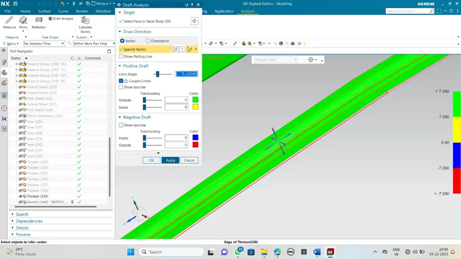
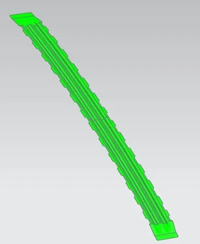
Draft analysis is used to find the feasibility to manufacture the deigned part using the appropriate manufacturing techniques. The minimum draft angle for sheet metal parts is 7º. This draft angle should be maintained in the design to ease the ejection of tool or part. This can be calculated using the ‘draft analysis’ command. To do the draft analysis we have to decide the tooling direction of the part. With respect to this tooling direction, draft analysis is carried out with angle limited to 7º. If the surface were changed into green colour, then the part is passed in draft analysis and it is feasible to manufacture this part. But if the surface changed into yellow or red colour then those surfaces have to be corrected until it changes to green.
For this project, the tooling direction for roof and its reinforcements were created individually in the part level and the draft analysis are also done for all the parts.
Draft analysis on center froof and its rail flanges;
Bow roof ends and center;
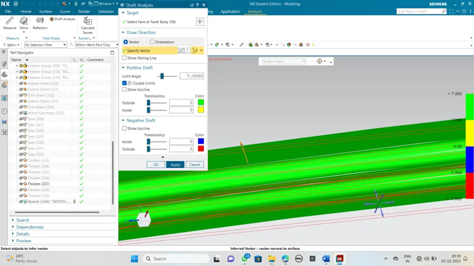
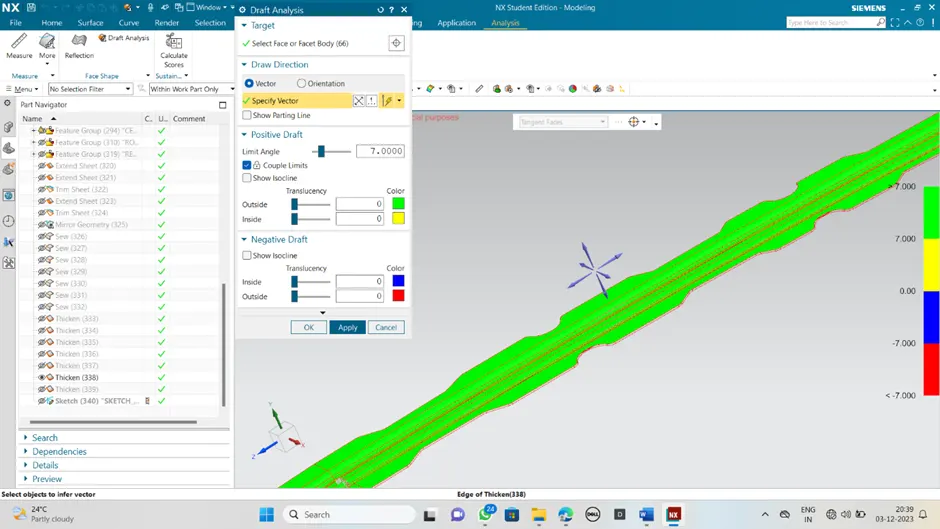
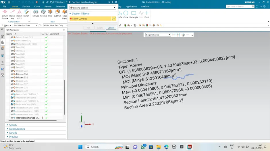
Section modulus:
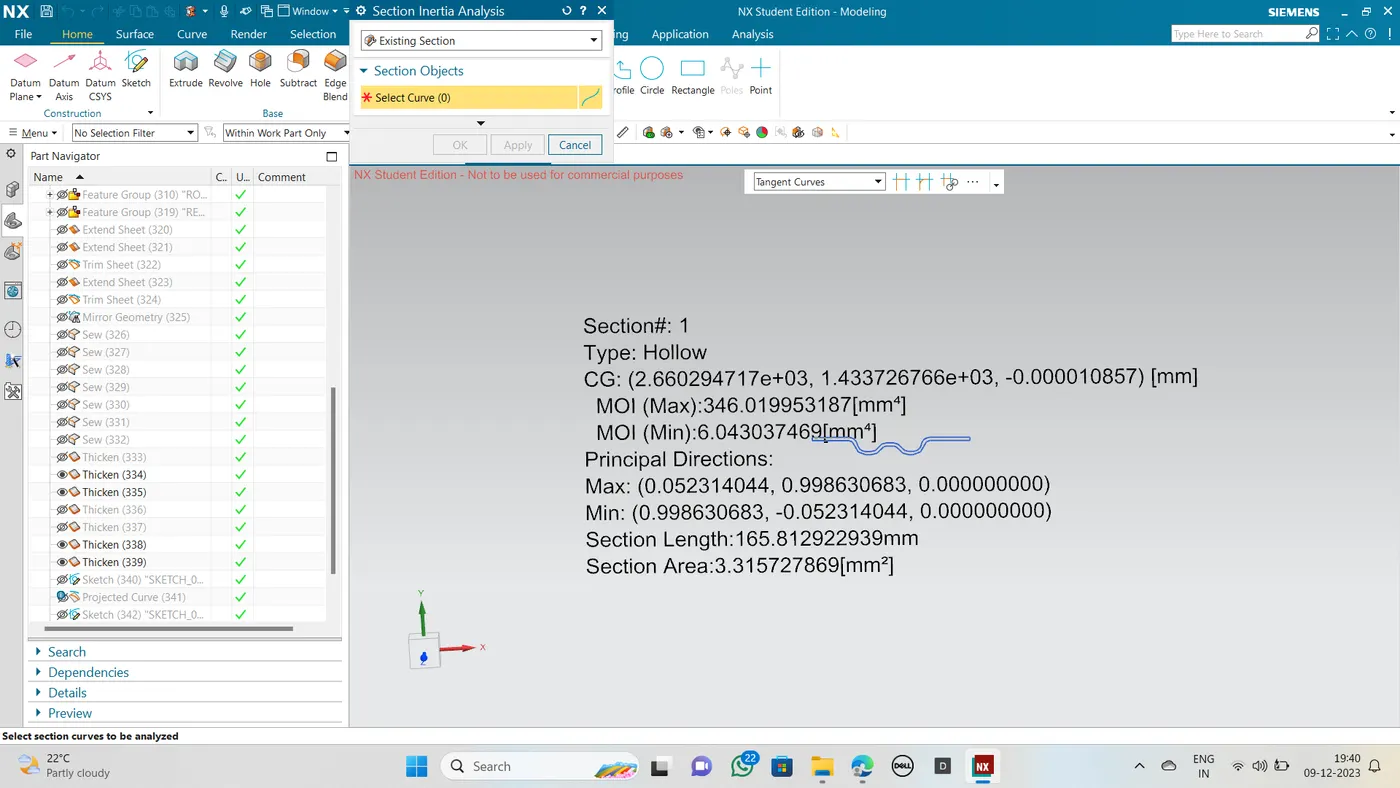
- to calculate section modulus ,first take component and take intersect cover in required plane by help of intersection commond.
- click on the section inetial from the ttool bar and select the component of bow roofs ends and bow roof centers.
- click on ok then we wiil get the section modulus with all relevant parameters .
- section modulus for bow roof-1
-
section modulus of center bow roof:
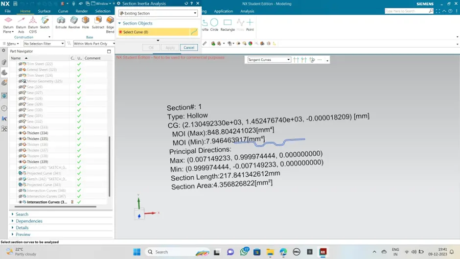
section moduls of bow roof-2
Heat distortion criteria:
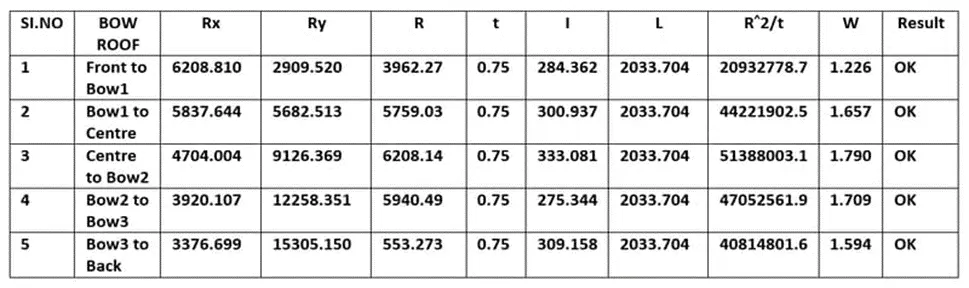
Heat distortion is the temperature at which the metal softens and deforms under a specific load. This study is done to check the ability of the roof to withstand high temperature with respect to the positioning of the reinforcements which contributes to increase the strength.
The heat distortion criteria of a roof can be calculated using the following formula,
W = [1.73 x 10^ (-3) x L] + [1.85 x 10^ (-8) x (R^2)/t] + [ 1.10x10^ (-3) x l] - 2.68
Were,
L = Roof Length in X-Direction[mm](Roof dimension in 0-Y)
R = Roof curvature
R = 2(Rx*Ry)/(Rx+Ry)
Rx = X curvature
Ry = Y curvature
t = Roof plate thickness [mm]
l = Bow Roof Span [mm]
Judgment Condition
OK< 2>
Snow load criteria:
Qr = [Iy x t2] / [α x s x [(Rx + Ry)/2]2 x 10-8]
Note: The or value given over here is correct. There was a typo error in the formula given in the video.
Where,
α = My x Lx2 x 10-12 , My = Y(Ly-Y)
t = Roof plate thickness [mm]
Ly = Distance between the front and rear roof Rails on the Vehicle along with 0Y[mm]
Length of Roof panel with the centre point between Roof rail Front /Rear as the front and rear reference point.
Lx = Distance between the Left and Right end of the roof on the Roof BOW [mm]
The width of the roof panel is exposed on the surface.
Y = Distance front Front Roof Rail to Roof BOW[mm]
s = Distance for which Roof BOW bears divided load [mm]
s = L1/2 + L2/2
Iy = Geometrical moment of inertia of Roof BOW (Y cross-section )[mm4]
Rx = Lateral direction curvature radius of roof panel Y cross-section on Roof BOW [mm]
Roof panel curvature Radius of the Length Lx in Front view
Ry = Longitudinal Direction curvature radius of the Roof panel X cross-section on Roof BOW [mm]
Roof panel X curvature radius of length s in Side view
Judgment condition
Qr ≥ 3.1
250 ≤ s ≤ 380
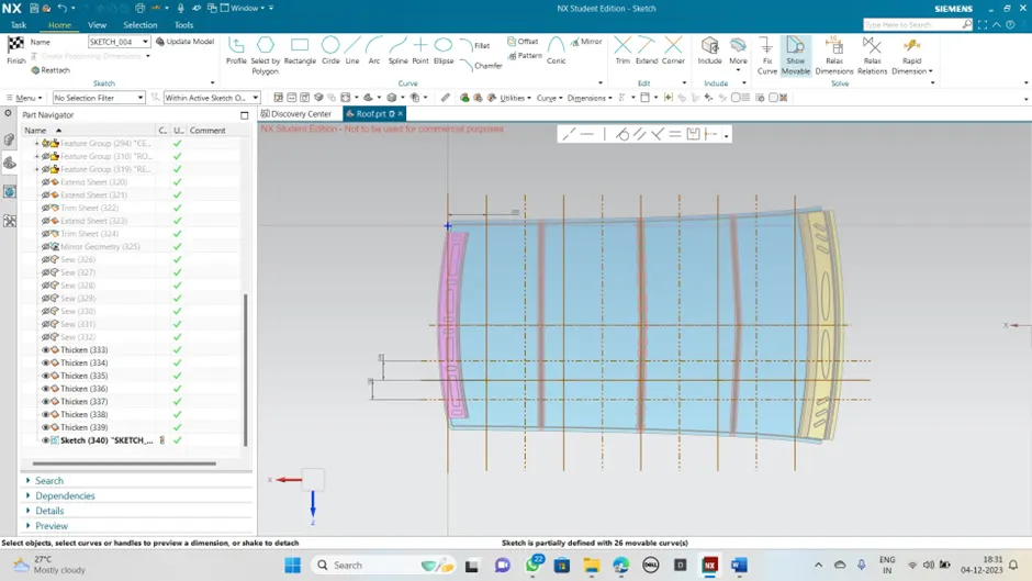
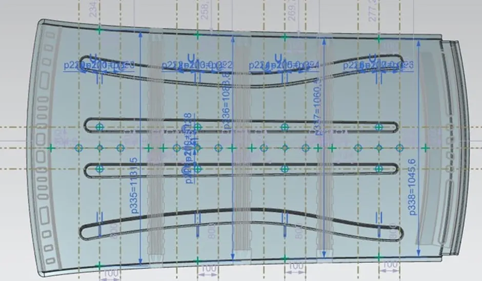
To find out the required values of the roof, a sketch was created on the xz plane. For this sketch, a line created at the 0y section which completely bisects the outer panel and then this line is offset to 300mm below. This offset line is further offset to 100mm above and below. Then at the sections (front roof to bow roof-1, bow roof-1 to centre roof, centre roof to bow roof-2 and bow roof-2 to rear roof) centre lines were drawn which is perpendicular to lines created before. These centre lines were offset to 100mm right and left, at all sections. With respect to these lines, the intersection points were created and projected to the outer panel surface. After projecting those points, 3-point arcs were created parallel and perpendicular to the 0y axis. Then their radius values were measured using the ‘local radius’ command.
Conclusion:
In this project done with the different design components of roof like designing of front roof rail, bow roof, rear roof rail and outer panel flanges, by following the appropriate methodology and all consideration required to the design in NX cad. And also performed the draft analysis on all components.