Roof Design
Aim:
To a given roof styling, create essential flanges and reinforcement.
Objective:
- To design the automotive roof based on the given styling surface and to analyze the prepared model to check the manufacturability and the feasibility of the design.
- To perform the section modulus study for the master sections and create for front roof rail, Bow roofs and center roof rail.
- To create the Ditch area and to perform the draft analysis.
Introduction to Roof:
An automotive roof or car top is the portion of the automobile that sits above the passenger compartment, protecting the vehicle occupants from Sun, Wind, Rain and other external element.
Under the styling surfaces that’s is seen from the outside, there are many other structures under the roof that contributes to its strength and stability. The number of such reinforcement structures/supports differ with respect to the size of the vehicle. They are primarily installed on the flatter areas of the roof to enhance the strength.
They are the Front Roof Rail, Rear Roof Rail, Center Rail and Bow Roof Design which are given Mastics and spot welded to the roof flanges & ditch are and improve NVH value by increasing the strength of the roof of using mastics sealants.
Types of Car Roofs:
- Convertible roofs.
- Hard Tops
- Sun roofs.
- T- Tops.
- Target tops.
- Vinyl roofs.
Design Consideration of roof:
- Visibility Criteria
- Head Clearance
- Curvature Study
- Heat Distortion and snow load criteria
- Draft Analysis
- Safety Parameters
Roof Crush test for passenger car:
Safety point of view vehicle roof plays a very crucial role especially roll over kind of accidents, In which vehicle tips over onto its side of the roof Vehicle rollover crashes are the cause of many fatalities and head, neck and spine trauma around the world.
Strength of the roof structure to occupant protection in real world roll over crashes, requiring the maximum moving distance of the roof structures should be less than 127 mm, (5 in), where the induced load is 1.5 times the vehicle weight.
For the test, the passenger ca shall be rigidly placed or positioned on a horizontal surface with the doors locked and the window closed. Furthermore, a flat, rigid block with a lower surface a rectangle measuring 30 inches wide by 72 inches long (762mm x 1829 mm) shall not move more than 5 inches (127mm), measured as the distances between the original location of the lower surface of the test device and its location as the specified force level is reached, when it is used to apply a forces of 1.5 times the unload vehicle weight (UVW) or 5000 lbs. (22224N), whichever is less. To either side or forward edge of the vehicle.
This test can be conducted on either side of the roof structure, the front left or the front right side but not on the both sides in one single test and still meet the requirement of the test. The rigid plate shall not move faster than 0.5 inches/second and the force applied on the plate shall not exceed the lesser of 1.5 times the unloaded vehicle weight (UVW) expressed in kilograms multiplied by 9.8 or 5000 lbs (22240N).
Also, the direction of the force shall be downward and perpendicular to the lower surface of the rigid plate and such that it moves in a straight line without rotation. The duration of the test shall not exceed 120 seconds. The longitudinal axis of the plate is pitched forward at a 5’ angle as viewed from the side of the passenger car as shown,
The lateral axis or the roll of the plate is such that it forms a 25’ outboard angle with a horizontal surface as viewed from the front of the passenger car as shown in below, fig
Master Section and its Parameters:
Joining Process:
Mastics are introduced between the roof outer panel and the reinforcements for joining. Where ever the mastics are introduced there is remarkable strength. Spot welding is also introduced to join the reinforcement and the outer panel.
Reinforcement and its types:
If the roof is flat, it is weak and cannot able to with stand the external load like snow load, roll over and etc. so in order to increase the strength of the roof, reinforcement like front roof rail, central roof rail, rear roof rail and the bow roof are introduced and joined in the flat surface of the roof with different joining process. In general, there are four types of reinforcement are used in the hard roof top they are,
- Front roof rail
- Central Roof rail
- Rear roof rail
- Bow roof rail
Roof ditch area and flanges:
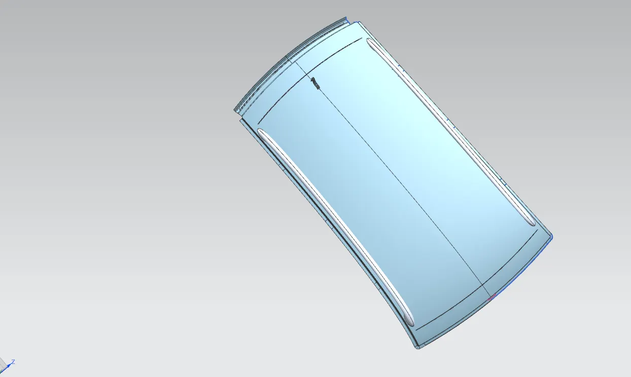
The roof ditch area and flanges are created in relation with visibility criteria, safe head distance , head liner and various other factors which govern the size of the roof rails and also which are related or connected to the roof like windshield.
- FRONT ROOF RAIL
The front roof rail plays a vital role in designing the roof rails because front roof rail forms the link between the roof , wind shield glass and head liner (trim).The visibility criteria and the head room space are the important factors which should be governed while preparing the master section for the front roof rail.
- Rear Roof Rail:
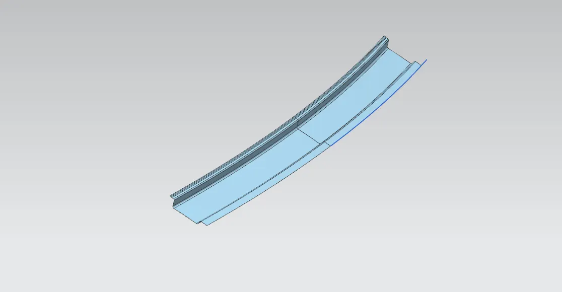
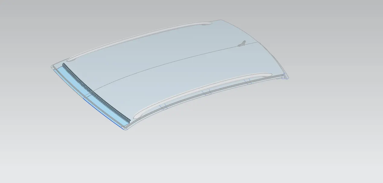
It is a reinforcement provided to the rear portion of the roof and it also features the tailgate mountings. The development of RRR is dependent upon the rear headroom clearance and rear visibility criteria. The minimum clearance from the headliner to the roof is should be 80mm which will vary from variant and region to region
Bow roof rail:
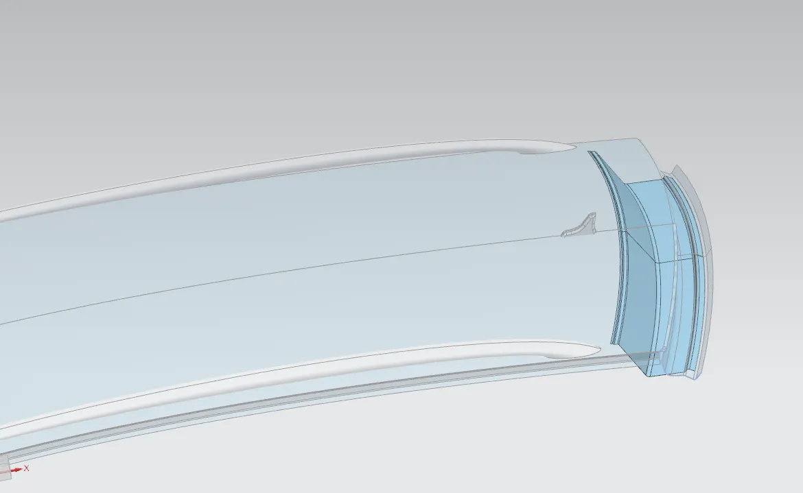
These are the reinforcements provided on the most flatter regions of the roof which are more susceptible to failure. The number of bow roofs depends upon the length of the roof i.e, longer roofs have more bow roofs like vans. For the development of the bow roofs, the styling surface and side ditch areas are taken as references.
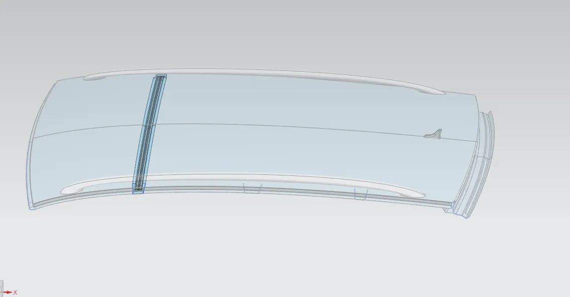
bow roof 1
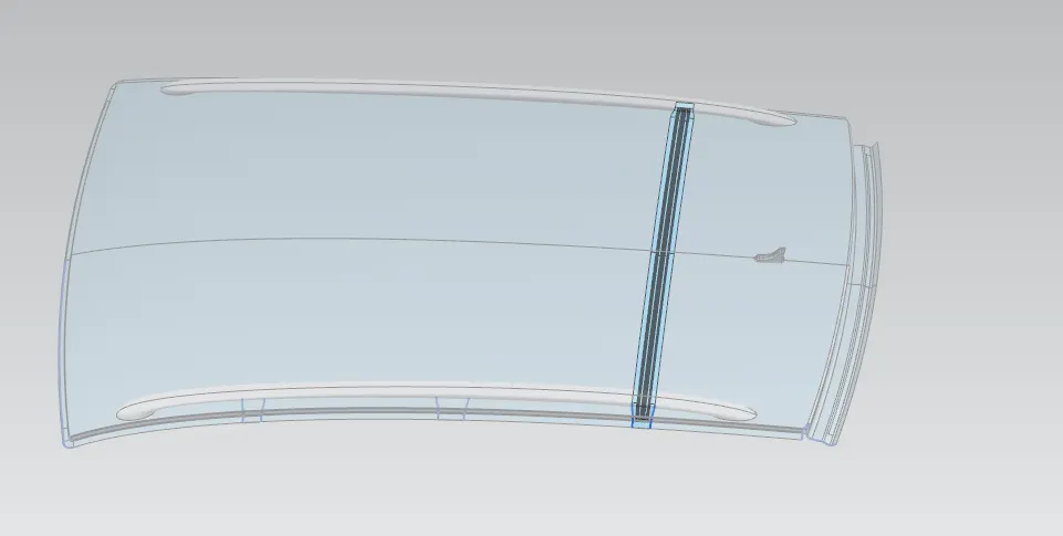
bow roof 2
Central Roof rail:
Central roof rail helps in providing effectively support to the flat area of the roof as it is more susceptible to failure under the action of load. Generally central roof rail is placed at the center of the roof which is connected to the B-pillar support structure. This central roof rail helps in the strength to the roof during the roll-over test
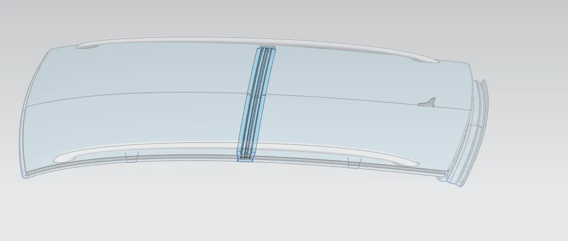
Joining Processes
The Flanges of the front and rear roof rail and flanges of the bow roofs and center roof rail are joined using the spot welding, whereas mastic sealants are provided along the roof rails to improve the strength and also to avoid bad marks on the aesthetic surfaces.
FINAL ASSEMBLY
Heated Distortion study on the roof:
The heat distortion study plays a major role in sheet metal usage. Heat distortion temperature is the temperature limit above which the material cannot be used for the structural applications. This study is used to predict the heat distortions temperature at the material where it start to soften when exposed to a fixed load at elevated temperature. In order to avoid bending or damages on the roof, based on the heat distortion temperature, this study will predict the bow roof position which helps to strengthen the roof.
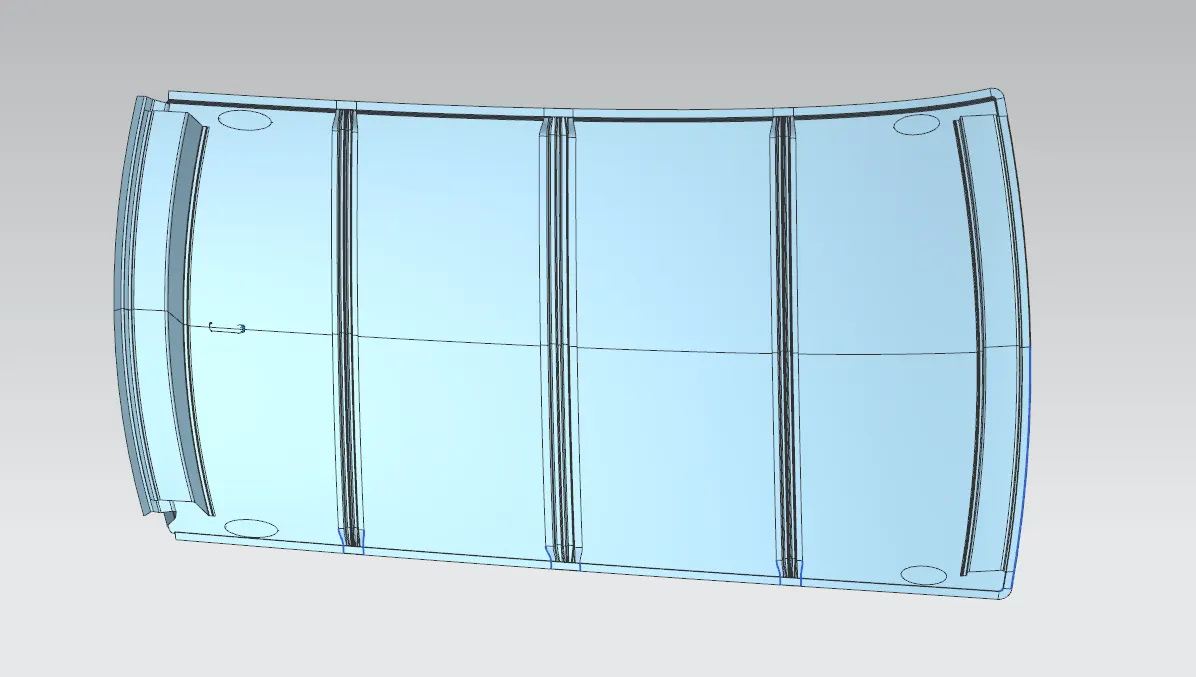
BOW – roof prediction study
W= [1.73x10 ^ (-3) x L] + [1.85 x 10^ (-8) x (R^2)/t] + [1.10 x 10^ (-3) x1] – 2.68
Where’
L = Roof strength in X- Direction [mm] (Roof dimension in 0 – Y)
R = Roof curvature
R = 2 (Rx*Ry) / (Rx + Ry)
Rx = X Curvature
Ry = Y curvature
t = Roof plate thickness [mm]
I = Bow Roof span [mm]
Judgement Condition: OK < 2.7 > 3.1
Here we have to find out Rx and Ry values. To find out
- Create a sketch on Top roof and draw a horizontal line at a center.
- Then offset this line below 300mm and called it as _3y line.
- From the _3y line offset 100 mm above and below and convert all these line into reference line.
- Draw the vertical lines at the middle of each reinforcements and offset it at 100 mm both sides.
- Intersection point is created where the lines are met.
- Project there points the outer roof panel.
|
Sr. no |
Bow |
Rx |
Ry |
R |
t |
I |
L |
R^2/t |
W |
Remarks |
|
1 |
Front to bow 1 |
5734.0139 |
2634.6127 |
3610.3668 |
0.75 |
402.9244 |
1810.3212 |
17379664.574 |
1.2528 |
Ok |
|
2 |
Bow 1 to centre |
4913.1091 |
6435.3683 |
5572.1424 |
0.75 |
448.1823 |
1810.3212 |
41398361.2345 |
1.6609 |
Ok |
|
3 |
Centre to bow2 |
3918.9922 |
10881.593 |
5762.5935 |
0.75 |
423.3174 |
1810.3212 |
44276645.1283 |
1.7366 |
Ok |
|
4 |
Bow 2 to back |
3266.6477 |
14677.7783 |
5738.7923 |
0.75 |
332.0162 |
1810.3212 |
43911649.4167 |
1.6294 |
Ok |
Snow Load Condition:
This test is done to know how the roof is behaving when there is a snow over. Normally due to the snow weight the dent will happen. But the roof should be designed in such a way that when the snow is removal the roof should go it its original position. This basic requirement for snow load criteria.
Qr = [Iy x t2] / [α x s x [(Rx + Ry)/2]2 x 10-8]
Where
α = My x Lx2 x 10-12
My = Y (Ly- Y)
Judgment Condition = Qr > 3.1
250 < s < 380
T = Roof plate thickness [mm]
Ly= Distance between the front and rear roof rails on the vehicle along with 0Y [mm]
Length of roof panel with the centre point between Roof rail front\Rear as the reference point of the front and the rear.
Lx = Distance between the left and right end of the roof on the Roof Bow [mm]
Width of the roof panel exposed on the surface.
Y = Distance front Roof Rail to Roof BOW [mm]
S = Distance for which roof Bow bears divided load [mm]
S = L 1/2 + L2/2
Iy = Geometrical moment of inertia of Roof Bow (Y Cross section) [mm4]
Rx = Lateral direction curvature radius of roof panel Y cross section on Roof BOW [mm]
Roof panel curvature radius of the length Lx in front view
Ry = Longitudinal Direction curvature radius of the roof panel X cross section on Roof Bow [mm]
Here we have to find out Rx and Ry values. To find that
Create a sketch on Top roof and draw a horizontal line at a centre.
Offset this line to 100 mm on both sides. Convert all these line into reference line.
Draw the vertical lines at the middle of each reinforcement and offset it at 100 mm both sides.
Intersection point is created where the lines are met.
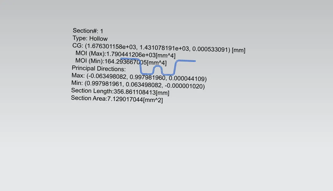
section innertia of bow roof1
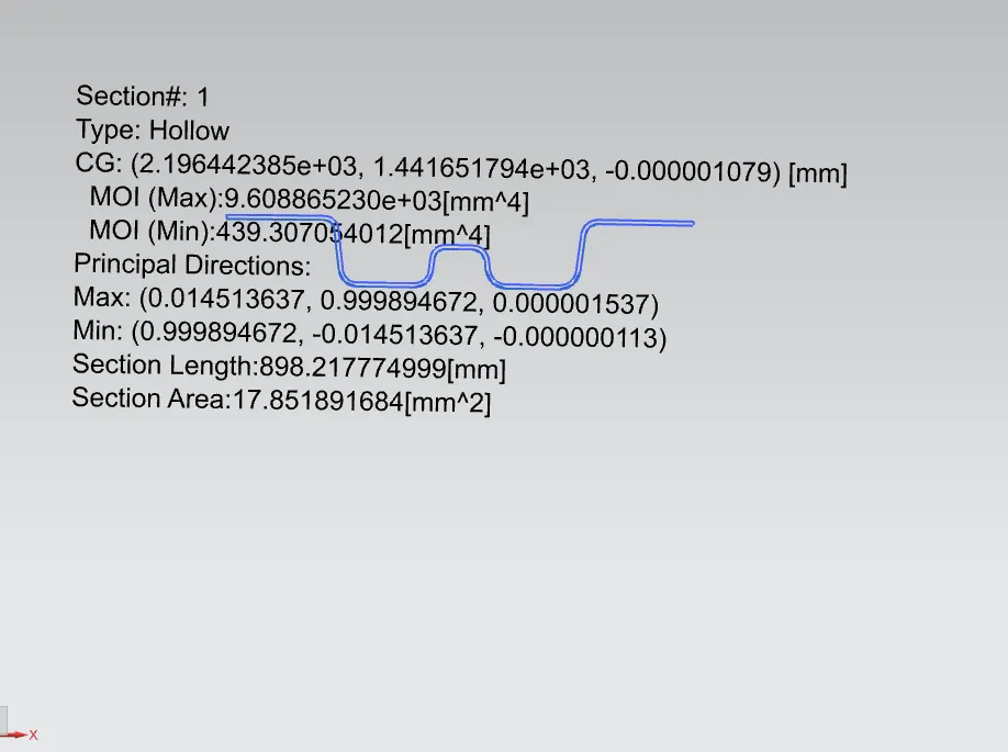
section innertia of center roof
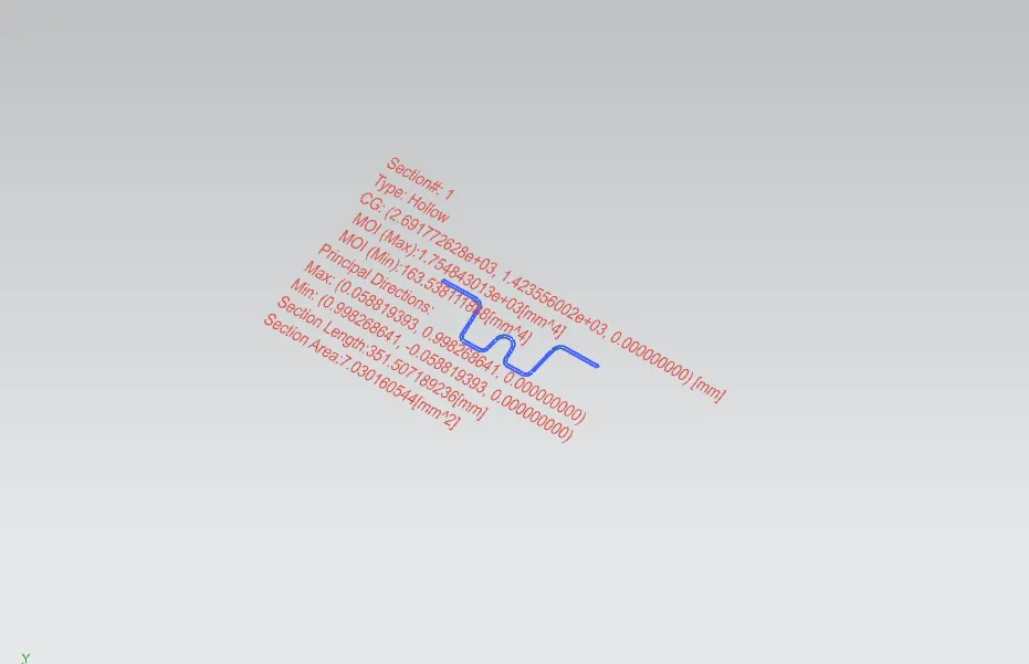
section inertia of bow roof 2
snow load
|
Bow roof |
Rx |
Ry |
L1 |
L2 |
Lx |
Ly |
t |
Y |
S |
My |
α |
Iy |
Qr |
result |
|
Front to Bow 1 |
4474.9650 |
2681.9905 |
259.9683 |
196.055 |
1135.2323 |
1952.1226 |
0.75 |
491.2259 |
245.597 |
717630.296 |
0.9248 |
164.29 |
37.75 |
OK |
|
Bow1 to Centre |
3777.2341 |
6353.5398 |
253.8866 |
266.4445 |
1084.3479 |
1952.1226 |
0.75 |
1011.5569 |
260.1655 |
951435.7237 |
1.1187 |
439.307 |
14.07 |
OK |
|
Centre to Bow2 |
4300.3039 |
11453.2579 |
254.2087 |
241.4504 |
1056.4385 |
1952.1226 |
0.75 |
1507.0193 |
247.7312 |
670779.2635 |
0.7486 |
163.538 |
9.54 |
OK |
|
Bow2 to Rear |
3984.3024 |
16521.1880 |
231.2576 |
259.9683 |
1043.2678 |
1952.1226 |
0.75 |
1952.1226 |
222.5516 |
0 |
0 |
0 |
- |
- |
Draft analysis
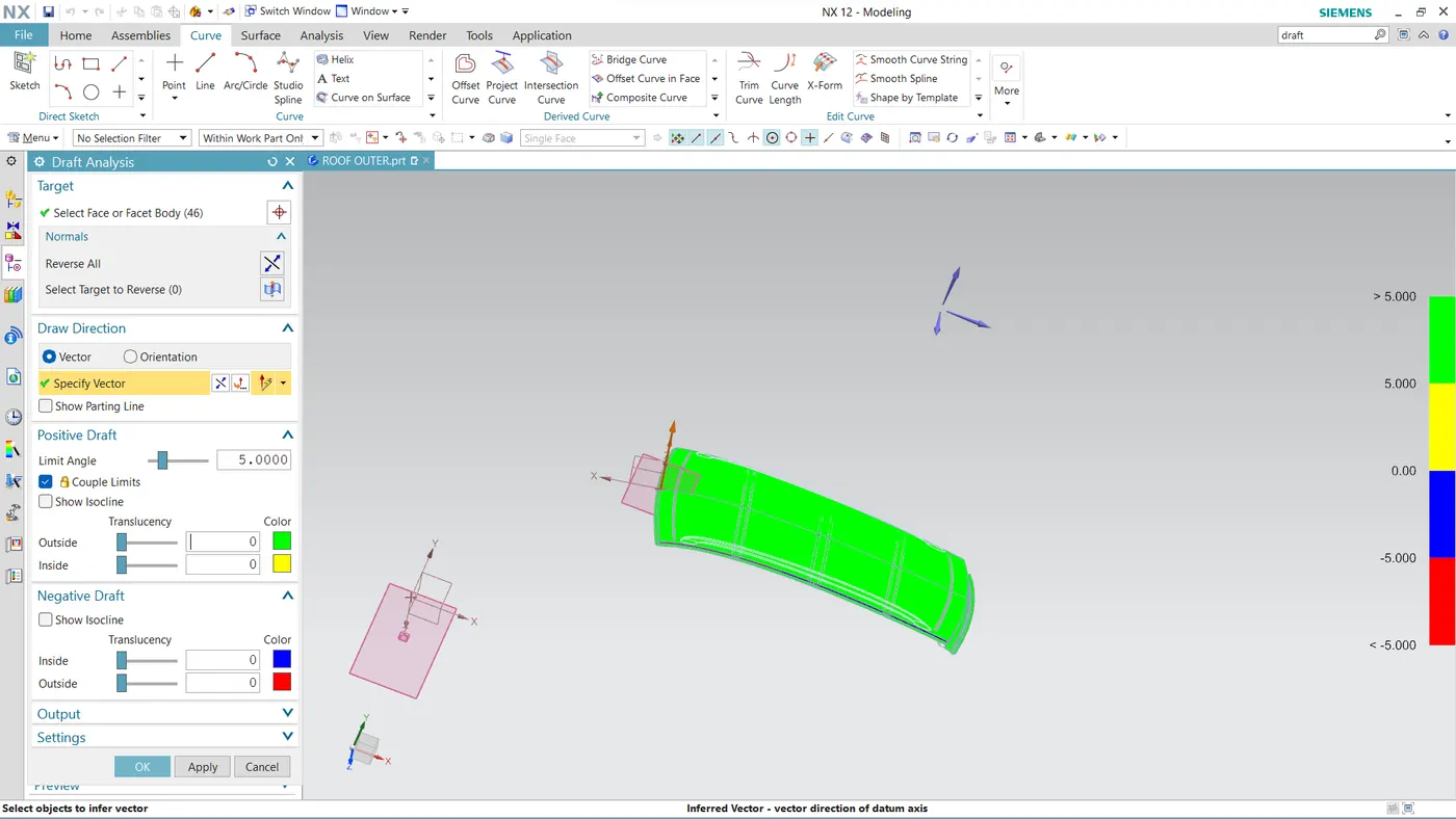
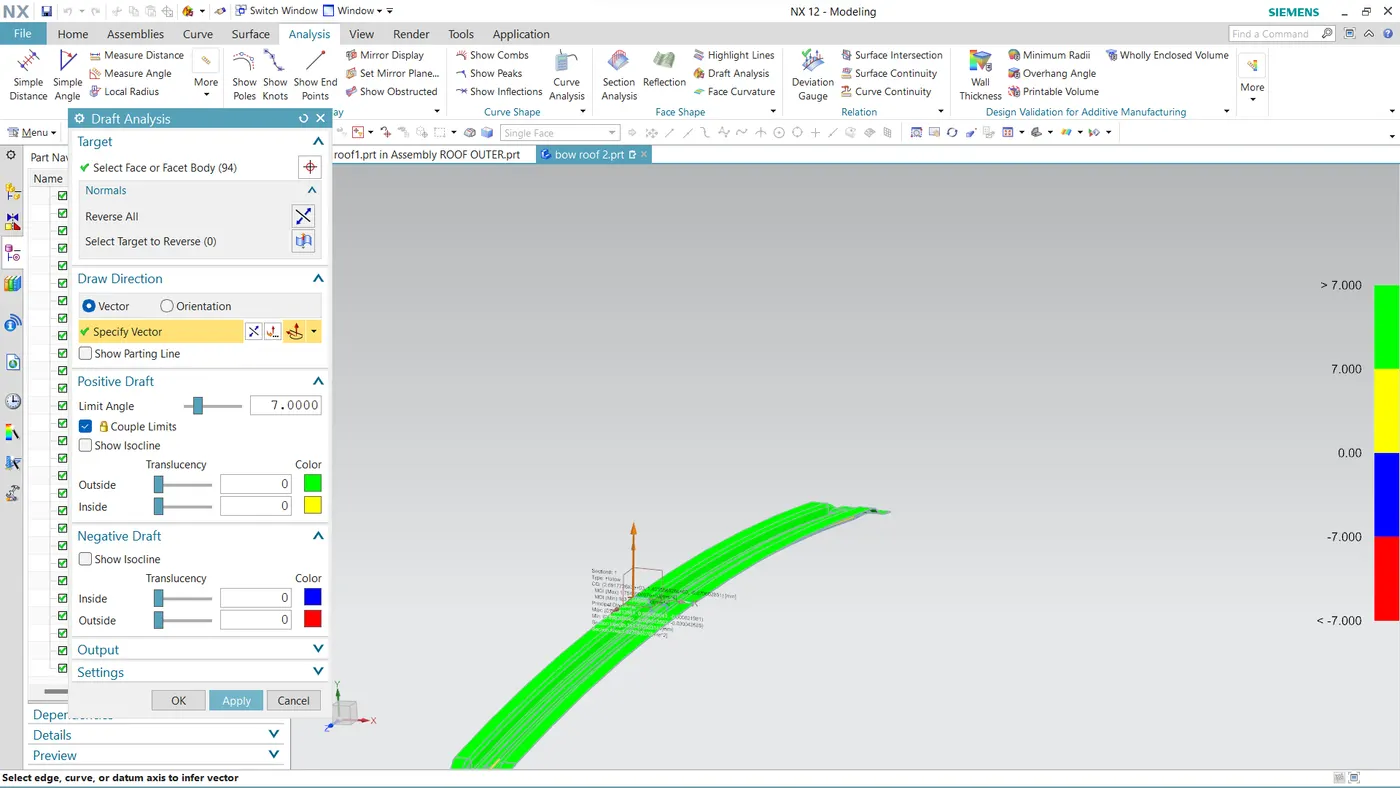
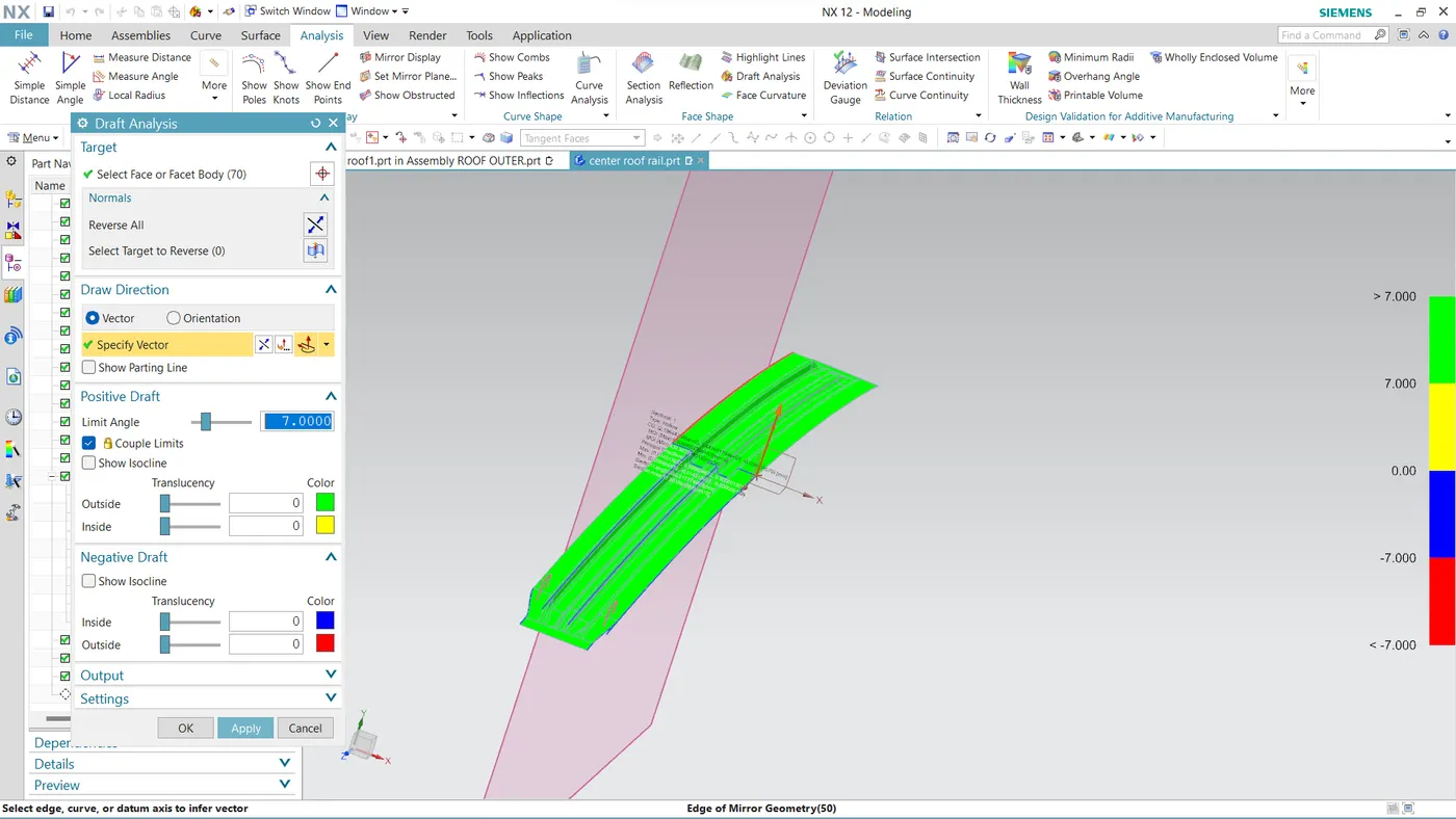
The draft analysis command enables you to detect if the part you drafted will be easily removed. This type of analysis is performed based on color ranges identifying zones on the analyzed element where the deviation from the draft direction at any point, corresponds to specified values.
Minimum draft angle of 7 degree is considered for analysis, green color infers on the parts that all face along the tooling direction has positive draft angle greater than 5 degree and passed in analysis.
- draft analysis of roof outer
- draft analysis of bow roof 2
- draft analysis of bow roof 1
- draft analysis of center roof
CONCLUSION
Thus the roof is designed with all the necessary reinforcements and roof rails according to the given master section and the styling surface, by considering all the design parameters. Also, the curvature study is done by taking the heat distortion and snow load criteria for determining the strength of the roof.