Roof Design
Project : CAR Roof Design Assembly:
Aim :
Create the Car Roof Assembly with Nessassry Roof Rail Like : Fron Roof Rail ,Rear Roof Eail , Reinforcement Center Roof Rail with Bow Roof -3,Bow Roof Rail-1,and Bow Roof Rail - 2 and Check the draft analysis , Moment of Inetia(MOI) and Calculation.
What is Objectives fo the Car Roof Assembly:
1.Create the Ditch area for given Roof Styling Surface and also extend the Ditch area Frame Size and angle as per mastic data.
2.Create the Roof Rails in Front,Rear and Reinforcement Center Roof Rail.
3.Support Bow roof would be created like Bow Roof-1,Bow Roof-2,Bow Roof-3.
4.Calaulating the curvature study if Heat Distortion condition and snowload criteria.
5.Analysis the Draft Analysis and check the Moment of inertia (MOI).
What is CAR Roof?
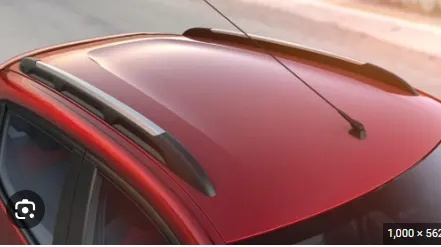
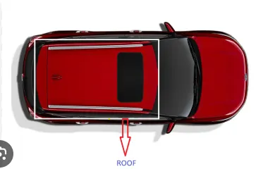
Automobile roof design or Car top is the portion of an automobile that site above the passanger compartment, protecting the vehicle the primery purpose of occupants like from sun,wind,rain, and other external elements.Because earliest automobile were designed in an era horse drawn carriage ,early automobiles are designed by similar material and designs.
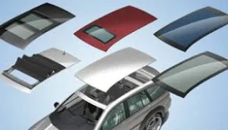
Now the roofs are developed in verious types,like
1.convirtable roof,
2.Roof Modules,
3.Hardtops,
4.T-tops,
5.Traga Tops,
6.Vinyl Roofs.
Design Consideration of Roof :
1.Visibility Criteria
2.Head Clearance
3.Curvature Study
4.Heat distortion and snow load criteria
5.Draft Analysis
6.Safty analysis
7.Safty Parameters
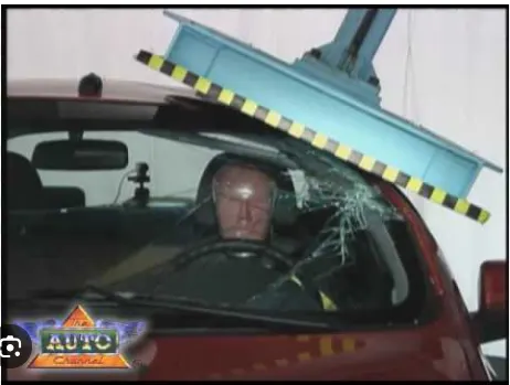
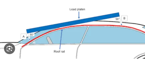
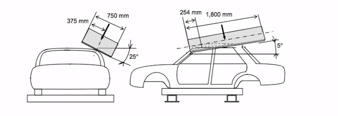
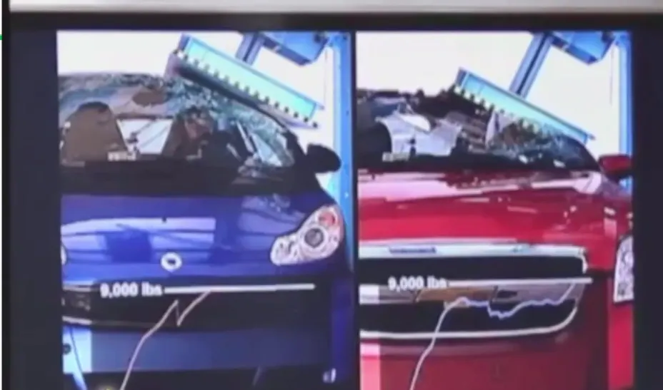
Roof Crush Test:
This type of tests basically use the quality of roof then check the strength ,performance,sustainability roof and roof bows.
Two way of test will be happend,they are ,1. Initial Condition Test,2.Sample Fixing Test.
Initial Condition Test:
1.Close and lock all the doors
2.Close the windows also
Sample Fixing Test:
The body still or chassis frame on a hard surface horizandally.
-
1.Crash Testing:
- Frontal Impact: Assess the roof's ability to withstand forces during a frontal collision.
- Side Impact: Evaluate the roof's performance in a side collision, considering the protection of occupants in rollover scenarios.
-
2.Rollover Testing:
- Evaluate the roof's strength and ability to maintain occupant survival space during a rollover event.
- Assess the effectiveness of the roof structure in preventing intrusion into the passenger compartment.
-
3.Dynamic Roof Crush Testing:
- Apply a vertical force to simulate the weight of the vehicle during a rollover.
- Measure the roof's resistance to deformation and assess the risk of injury to occupants.
-
4..Static Roof Load Testing:
- Apply a static load to the roof to assess its structural integrity under various conditions.
- Determine the maximum load the roof can withstand without significant deformation.
-
5.Roof Strength-to-Weight Ratio Testing:
- Evaluate the strength of the roof in relation to the weight of the vehicle.
- Assess compliance with safety standards that prescribe minimum strength-to-weight ratios.
-
6.Water Leak Testing:
- Ensure that the car roof is effectively sealed against water ingress.
- Simulate rainfall conditions to identify and address potential leaks.
-
7.Wind Noise Testing:
- Evaluate the aerodynamics and sealing of the car roof to minimize wind noise.
- Conduct tests in a controlled wind tunnel environment.
-
8.Sunroof Testing:
- Assess the structural integrity, sealing, and safety features of sunroof systems.
- Ensure proper operation and resistance to water penetration.
-
9.Material and Component Testing:
- Test the materials used in the roof structure for strength, durability, and corrosion resistance.
- Assess the performance of components such as pillars, roof rails, and attachments.
-
10.Durability Testing:
- Subject the car to long-term exposure to environmental conditions, including sunlight, temperature variations, and vibrations, to assess long-term durability.
-
11.Crash Avoidance Technology Testing:
- Evaluate the integration of advanced driver assistance systems (ADAS) related to roof safety, such as lane departure warning and automatic emergency braking.
Master Data :
Master data or mastic data is Define the any automobile part or product is how to design as per standard and regulation then consider the what requirement of current setution ,It is collect the all detailes is various prespectives in before create the masterdata .That is called Mastic data.
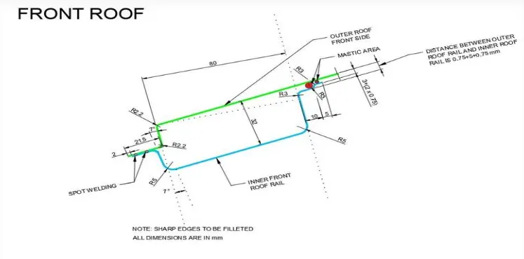
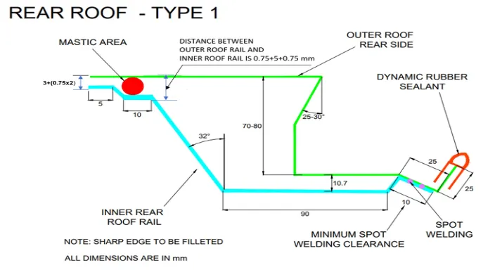
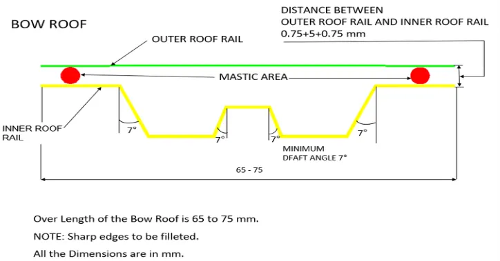
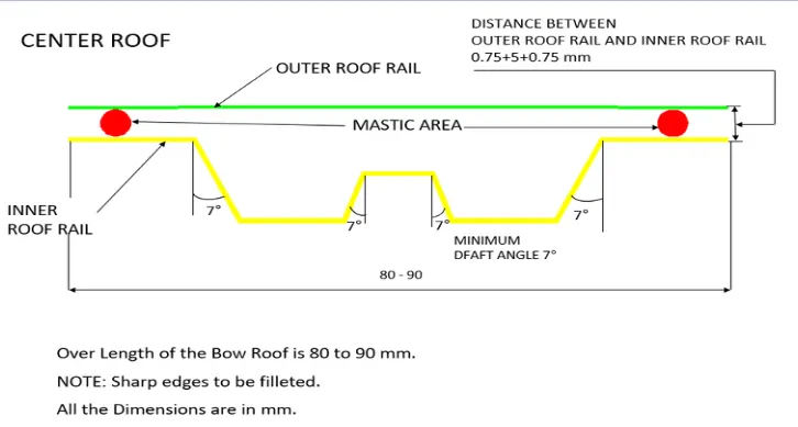
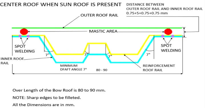
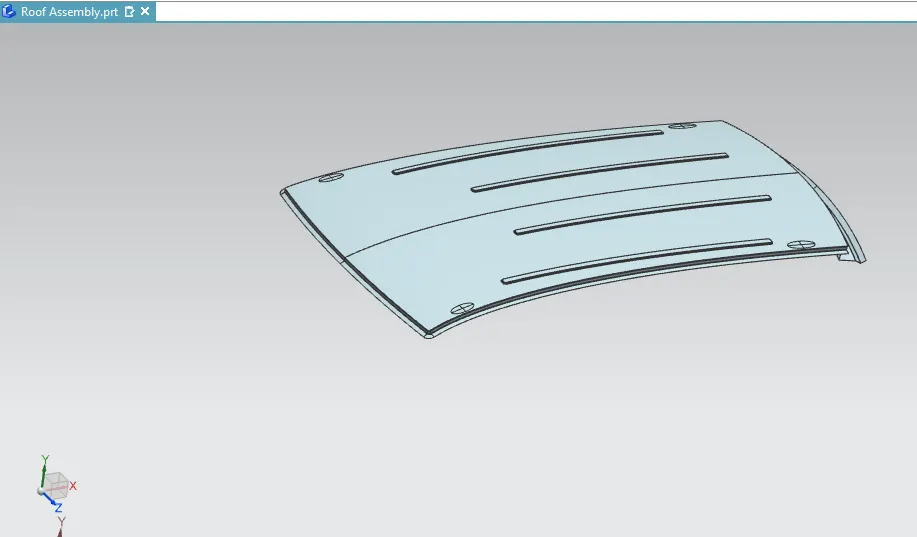
Creating the Roof Surface :
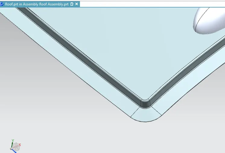
Desiging the roof Surface by using Styling Part initialy the roof surface corner are sharp Corner.then we have to change the corner is sharp face to Fillet face . The raidus of fillet is 5mm then create the Ditch area in by using styling surface of the roof in both side of y Direction .
Create the Front and rear Side (Ditch Area )Frame as per mastic data.Beacuse the wind Sheeld Glass and Back door are place in roof front and rear side.
Front Side Ditch area Frame could be created by us law extension command and value of length is 15.5mm is vertically and 21.5mm is horizandally with angle - 83 Deg & 105 Deg.Rear Side is Law extension is vertically 40mm + 40mm then angle was 150 Deg & 62 Deg and horizandally length is 70mm,26mm& 25mm and Angle was 90deg,-25 deg,65 deg.
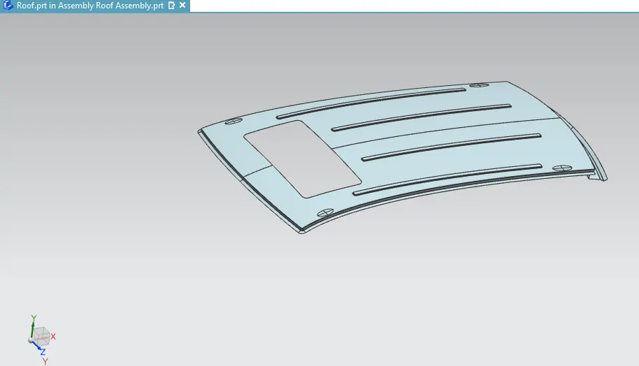
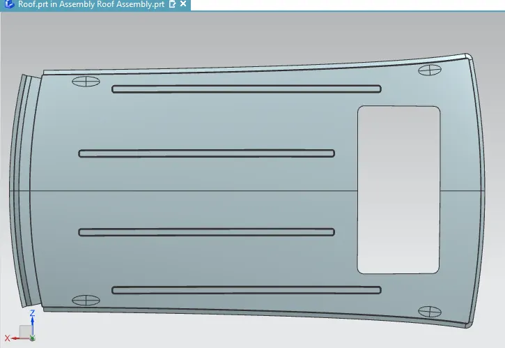
Make Sketch by using sunroof design and embosses.surroof are located in front side on the roof surface.they located inbetween in front rail into bow roof 1.the size was 762mm x 213mm R- 30mm
All Sharp corner is 2mm Raidus and Roof thickness is 0.75mm upward.
WITH SUN ROOF :
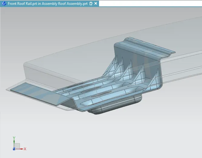
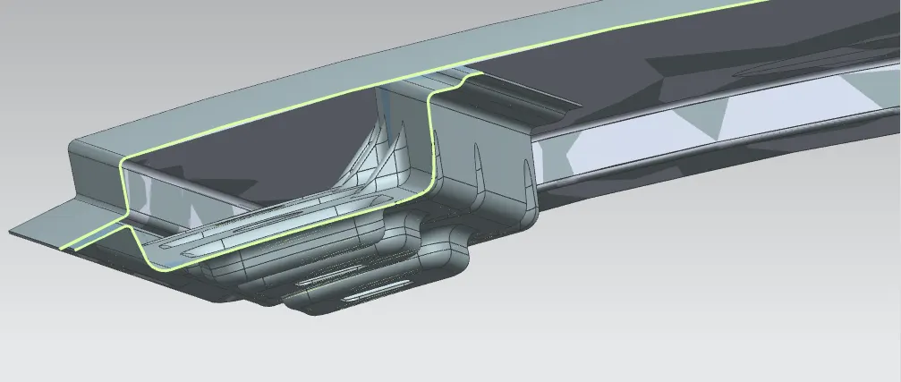
Design the Front Roof Rail:
The front roof rail serves as an additional companent that rainforces the roof structure.it includes various features such as supporting brackets for map lamps and room lamps ,enchanging functionally and convenience.
Wave geometric linker in outer roof and 32mm offset in Roof surface and trim the surface in 80mm length in Y direction and 80mm in distance X direction from side corner in roof surface.inCreate the Law extension in 15.5mm verically in 97 deg Angle corner radius is 5mm and Horizandally 19.5 mm length and 90deg angle then corner radius is 3 mm in law extension.
front roof rear side is also same process create the law extension in 27mm length and 83 deg angle in vertical direction sharp corner radius is 5mm also horizandal side 10mm and 95 deg angle then vertical side length is 2.7mm length 65 deg angle and also horizandal side is length 5mm and angle is 115mm .the distance between in outer roof surface into inner roof surface is 32mm and 5mm and 3mm.fillet radius is 3mm.
Make Sketches in required design and develop the embosses and Trim the surface .because this method create the stress relief in roof surface.
After that we will Create the Tickness is 0.75mm in downward.
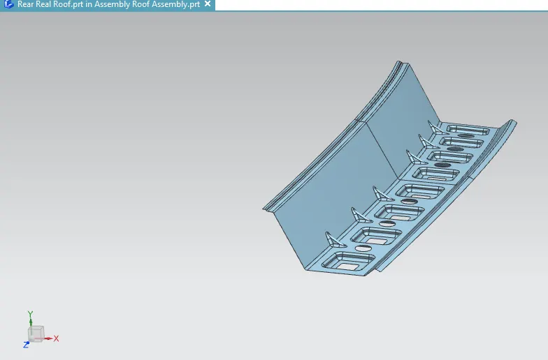
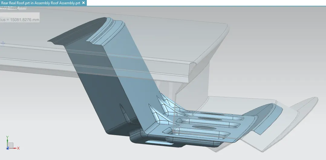
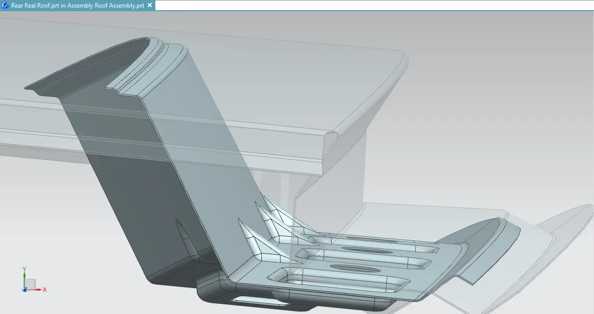
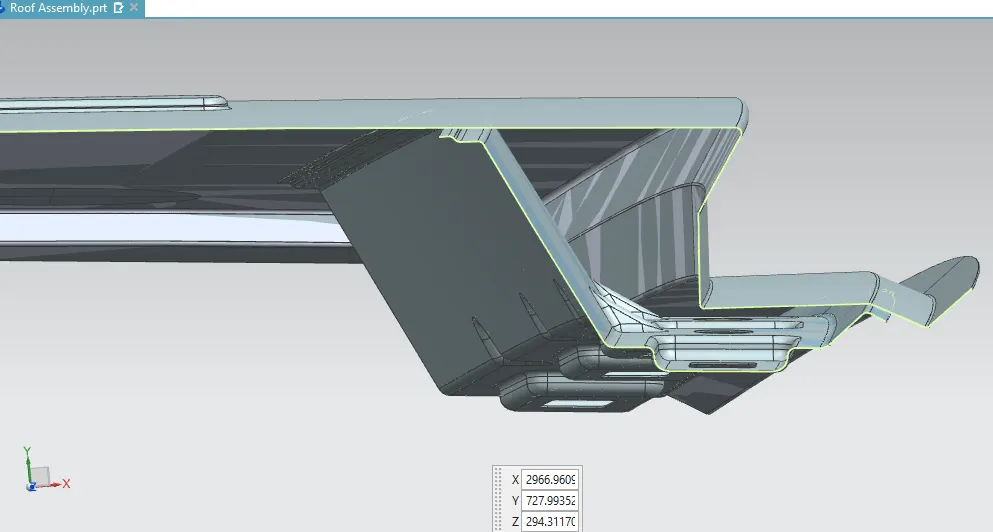
Rear Roof Rail:
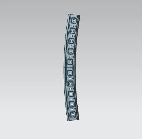
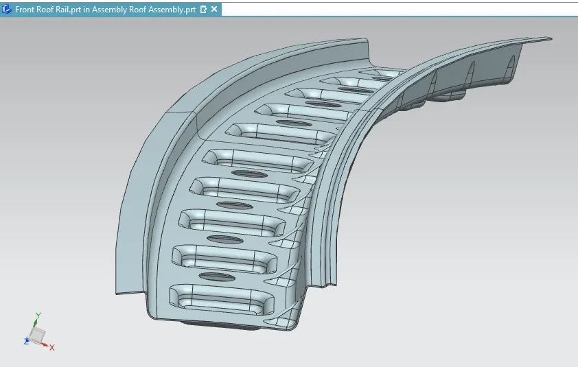
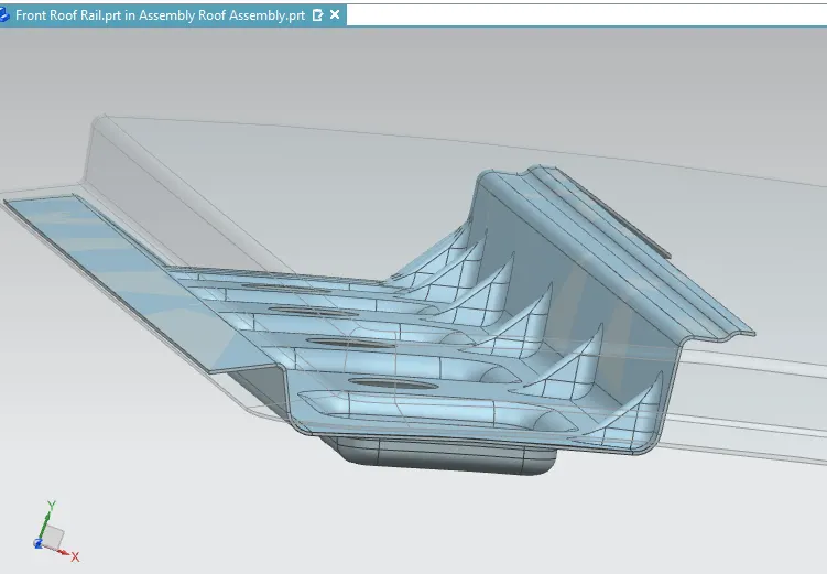
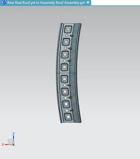
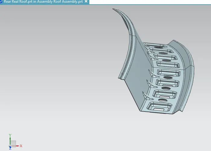
The rear roof rail primarily supports the roof of the car.it also assists in the operation of the back door hinges.facilitating smooth opening and closing.
Create the Wave geometric linker and offset in 90.7mm distance in downward and trim surface size in Y direction in 90mm and 80mm from x direction of side ditch area.
And use law extension command then length is 100mm and 3.6mm in 122 degree and 225 Deg angle and corner fillet radius is 5mm ,3mm in vertical direction then 10mm and 5 mm length is 60 Deg angle and -45 Deg , radius is 3mm in horizandally. same process is doing on rear side of Rear roof rail.the angle is 43mm and length is 22.6mm in vertical direction. and -67 mm angle,10mm length of horizandal direction .both corner fillet radius is 3mm in rear side .
create the Sketches in required design and develop the embosses and Trim the surface .because this method using stress relief in roof surface.
Tickness of the Rear Roof Rail is 0.75mm downward.
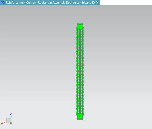
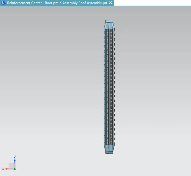
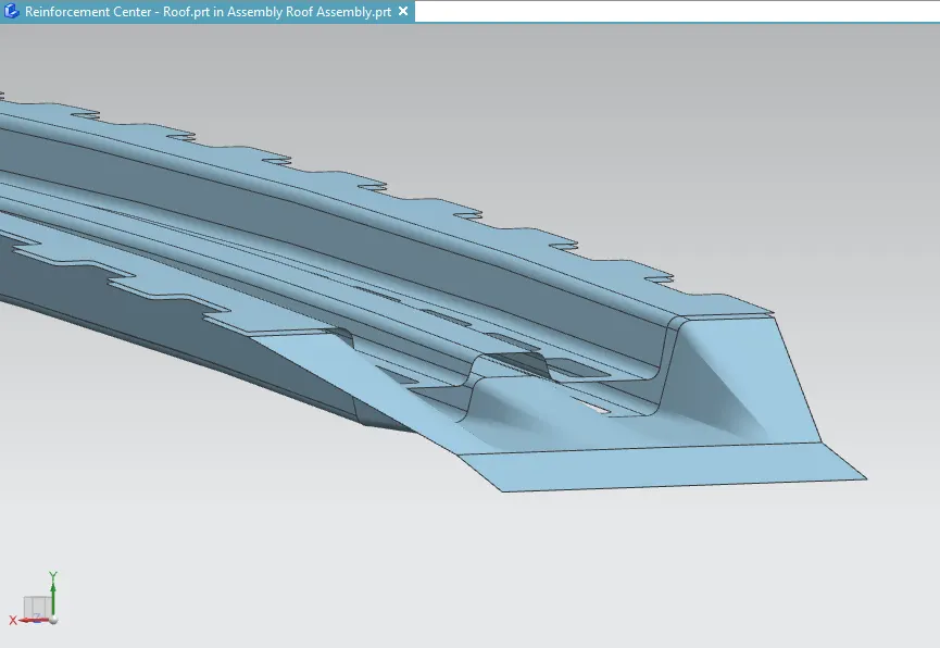
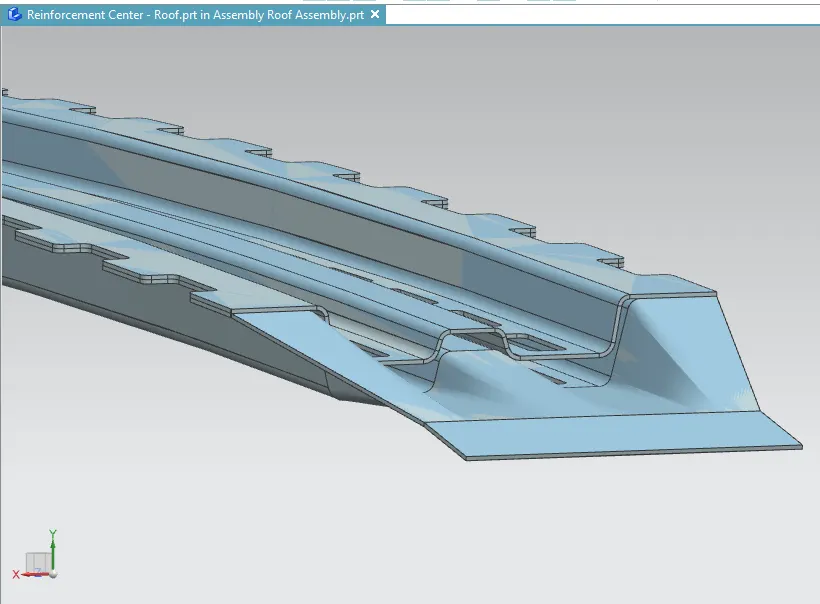
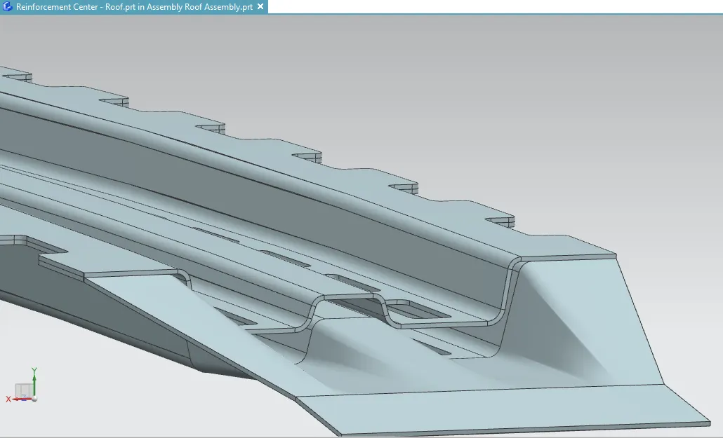
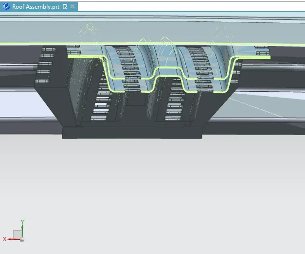
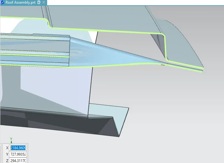
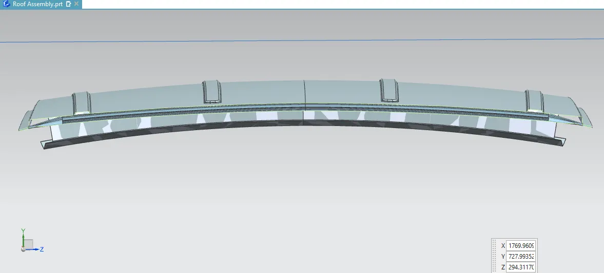
Reinforcement Center Roof:
The reinforcement center us a crucial structural element of the roof.it acts as the primary support member,absorbing energy during side impact or crashes.in smaller cars,it also functions as a bow roof ,providing additional strength and rigidity.
This Roof is located in Center of front roof rail and Rear roof rail .Create the wave geometric linker and offset in 5mm distance then trim in 90mm length X direction and 51.49 mm distance from side ditch area in Y direction.
Again offset in two times in 5mm and 10mm Distance respectively.Trim the Three Surface is following length - 18mm,11.6mm.
Connected the Surface by using in Through curves in 7 deg angle and Draw in sketch on top of Roof surface in which design you want.using trim sheet option to make the trim of the surfaces.
Then using Sew command to connect the all surfaces and make radius in sharp corner. Fillet radius is 2.2mm .Finally using Mirror geometry the another side will be happend.
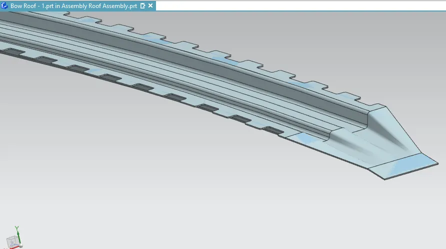
Bow Roof - 1:
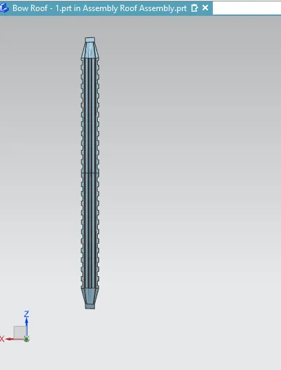
Bow roofs are roof- supporting rais designed to enchance the cverall stiffness and structural integrity of the vehicles roof.they are engineered based on specific criteria such as heat distortion and snow load condition to ensure optimal performance and safety
This Roof is located inbetween on the front roof real into reinforcement center roof .Create the wave geometric linker and offset in 5mm distance then trim in 75 mm length X direction and 65 mm distance from side ditch area in Y direction.
Again offset in two times in 5mm and 10mm Distance respectively.Trim the Three Surface is following length values- 14.5mm,10.6mm
Connected the Surface by using in Through curves in 7 deg angle and Draw in sketch on top of Roof surface in which design you want.using trim sheet option to make the trim of the surfaces.
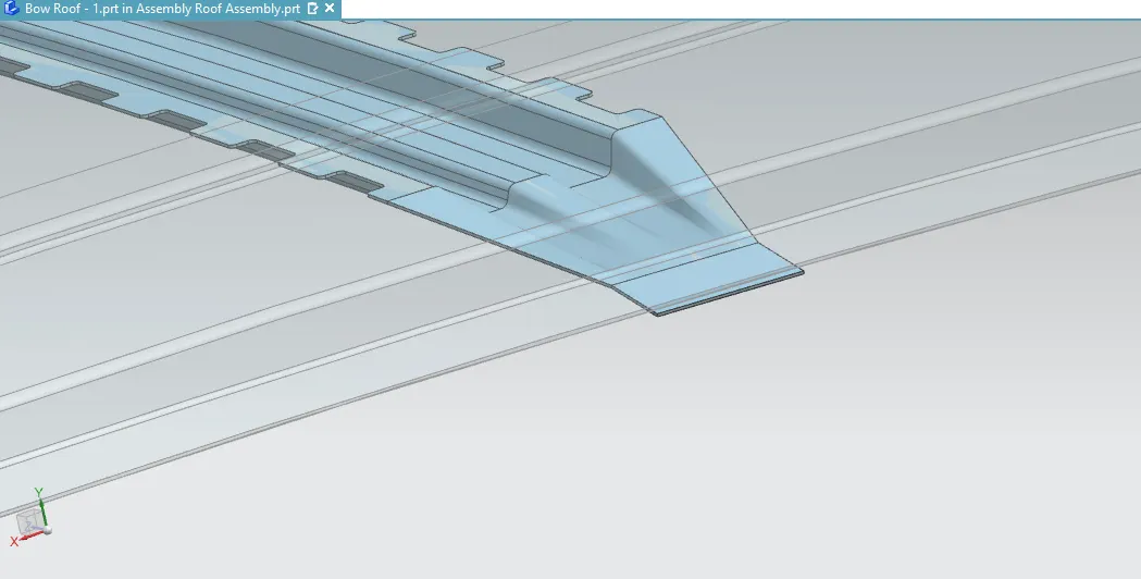
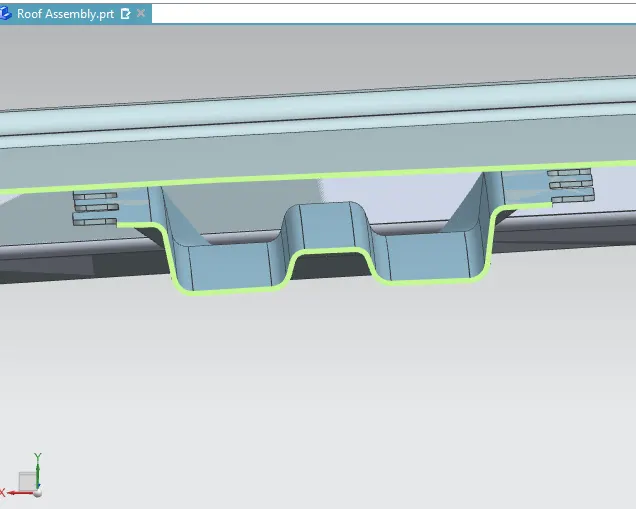
The ditch area also have in bow roof-1 because the bow roof-1 end would be placed in below of outer roof surface ditch area.the distance between in two ditch area is 1.5mm. then 18mm offset and trim from distance bow roof frame end in x direction side.
So Again use geometric linker commend in outer roof ditch area and offset in 1.5mm below then trim in require size .
using Sew command to connect the all surfaces and make radius in sharp corner. Fillet radius is 2mm . Finally using Mirror geometry the another side will be happend.
Bow Roof - 2:
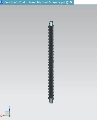
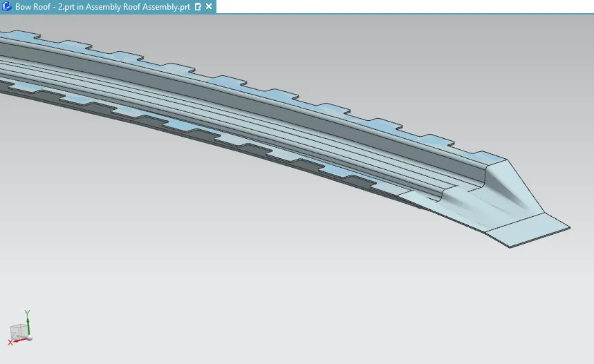
Bow Roof - 2 is located inbetween on the reinforcement center roof into Rear roof rail.we have make on the wave geometric linker and offset in 5mm distance then trim in 75 mm length X direction and 65 mm distance from side ditch area in Y direction.
offset on again two times in 5mm and 10mm Distance respectively.Trim the Three Surface is following length - 14.5mm,10.6mm.
Then the Surface is connected by using in Through curves and 7 deg angle and Draw in sketch on top of Roof surface in which design you want.using trim sheet option to make the trim of the surfaces.
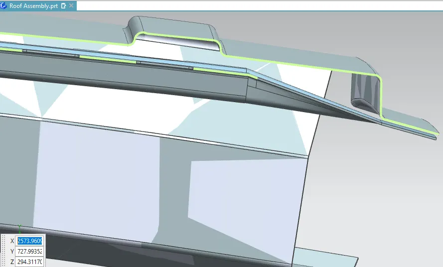
The ditch area also have in bow roof-3 because the bow roof-3 end would be placed in below of outer roof surface ditch area.the distance between in two ditch area is 1.5mm. then 18mm offset and trim from distance bow roof frame end in x direction side.
So Again use geometric linker commend in outer roof ditch area and offset in 1.5mm below then trim in require size .
Sew command is used to connect the all surfaces and make radius in sharp corner. Fillet radius is 2mm . Finally using Mirror geometry the another side will be happend.
Inner Roof Rail or Bow Roof - 3:
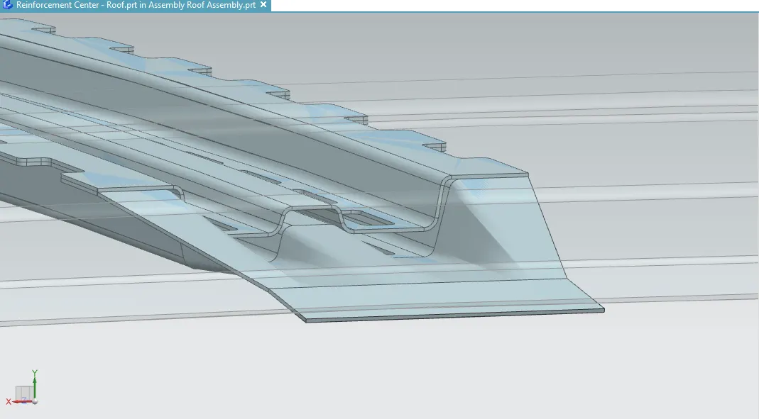
Inner Roof rail is located Center of front roof rail and Rear roof rail also placed on the below of reinforcement center roof rail.we have been make on the wave geometric linker and offset in 5.75 mm and trim in 90 mm X direction and 51.49 mm from side ditch area in Y direction.
offset on again two times in 8 mm and 15 mm Distance respectively.Trim the Three Surface is following length - 16mm,11.52mm values.
Then the Surface is connected by using in Through curves and 7 deg angle and Draw in sketch on top of Roof surface in which design you want.using trim sheet option to make the trim of the surfaces.
The ditch area also have in bow roof-3 because the bow roof-3 end would be placed in below of outer roof surface ditch area.the distance between in two ditch area is 1.5mm. then 14mmmm offset and trim from distance bow roof frame end in x direction side.
So Again use geometric linker commend in outer roof ditch area and offset in 1.5mm below then trim in require size .
Sew command is used to connect the all surfaces and make radius in sharp corner. Fillet radius is 2mm . Finally using Mirror geometry the another side will be happend.
Curvature Study:
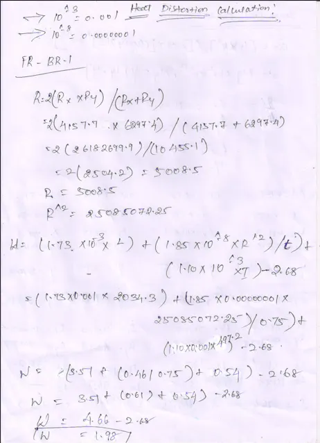
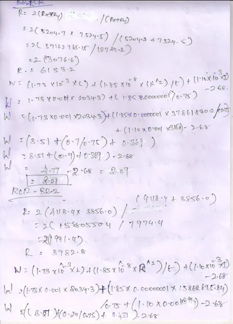
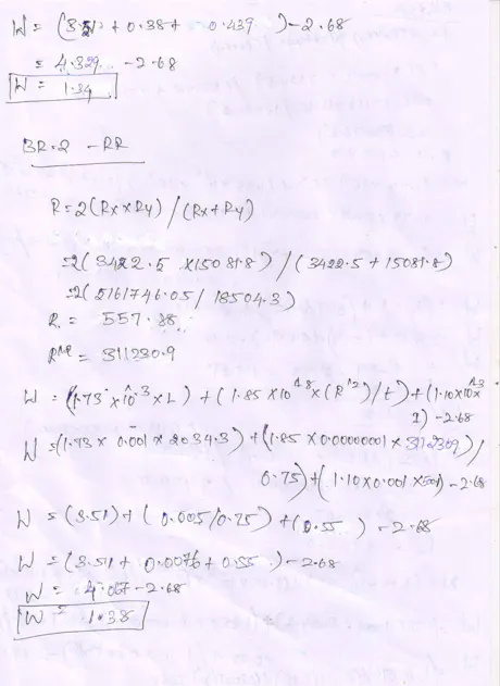
Heat Distortion Calculation:
Heat distortion criteria are used to determine the temperature at which materials begin to "soften" or deform when subjected to a specific load under elevated temperatures, caused by the heat radiating from the sun. In the context of a car's roof, these criteria help identify the temperature threshold at which the metallic regions of the roof may undergo changes due to heat exposure.
W = [1.73 x 10^(-3) x L] + [1.85 x 10^(-8) x (R^2)/t] + [ 1.10x10^(-3) x l] - 2.68
Where,
L = Roof Length in X-Direction[mm](Roof dimension in 0-Y)
R = Roof curvature
R = 2(Rx*Ry)/(Rx+Ry)
Rx = X curvature
Ry = Y curvature
t = Roof plate thickness [mm]
l = Bow Roof Span [mm]
OK< 2.7

Snow Load Criteria:
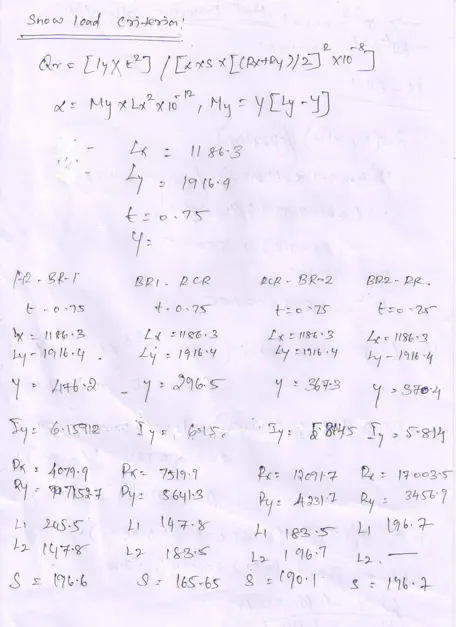
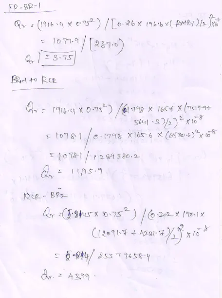
Snow load criteria are essential for determining the maximum amount of snow weight that a car's roof can withstand without failure. During the winter season, snow can accumulate on the top surface or roof of a car, exerting a significant mass. If the weight of the snow load exceeds the design capacity of the roof, it can lead to structural failure or damage. By considering snow load criteria, engineers and designers can ensure that the roof is constructed to safely support the expected weight of snow during winter conditions.
Qr = [Iy x t2] / [α x s x [(Rx + Ry)/2]2 x 10-8]
Note: The Qr value given over here is correct. There was a typo error in the formula given in the video.
Where,
α = My x Lx2 x 10-12 , My = Y(Ly-Y)
t = Roof plate thickness [mm]
Ly = Distance between the front and rear roof Rails on the Vehicle along with 0Y[mm]
Length of Roof panel with the center point between Roof rail Front /Rear as the front and rear reference point.
Lx = Distance between the Left and Right end of the roof on the Roof BOW [mm]
The width of the roof panel is exposed on the surface.
Y = Distance front Front Roof Rail to Roof BOW[mm]
s = Distance for which Roof BOW bears divided load [mm]
s = L1/2 + L2/2
Iy = Geometrical moment of inertia of Roof BOW (Y cross-section )[mm4]
Rx = Lateral direction curvature radius of roof panel Y cross-section on Roof BOW [mm]
Roof panel curvature Radius of the Length Lx in Front view
Ry = Longitudinal Direction curvature radius of the Roof panel X cross-section on Roof BOW [mm]
Roof panel X curvature radius of length s in Side view
Qr ≥ 3.1
250 ≤ s ≤ 380

Section Modules:
What is Section Modules:
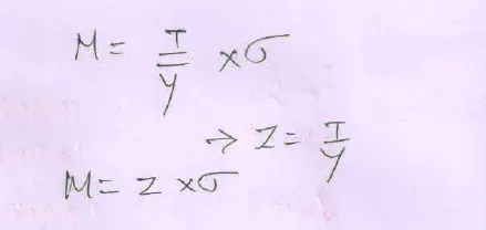
Section modules is the ratio of area moment of ineratia about natural axis and to the distance of outer most fiber from the netural axis.
Z = I/Y (Unit = mm3 or m3 )
Z = Section Modulus
I = Moment of Inertia
Y = distance from the neutral axis to the outer most fiber.
What is Natural Axis ?
Natural Axis is the cross section of beam or shaft and there is no longtudinal stress or strain.That is called natura axis.
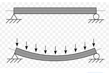
Area Moment of Inertia:
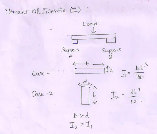
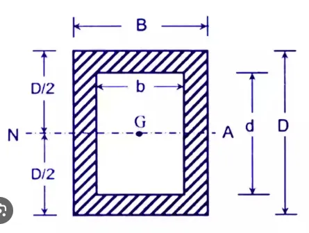
Is a Second moment of area or Second area moment or Quadritc moment of area is known as moment of inertia.is the property of two dimensional plane shape shows how the points are dispresed in an arbitatry axis in cross sectional plane that is called area moment of inertia.
They are two cases are there, That is,
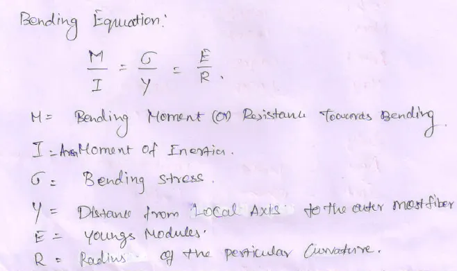
Bending Equation:
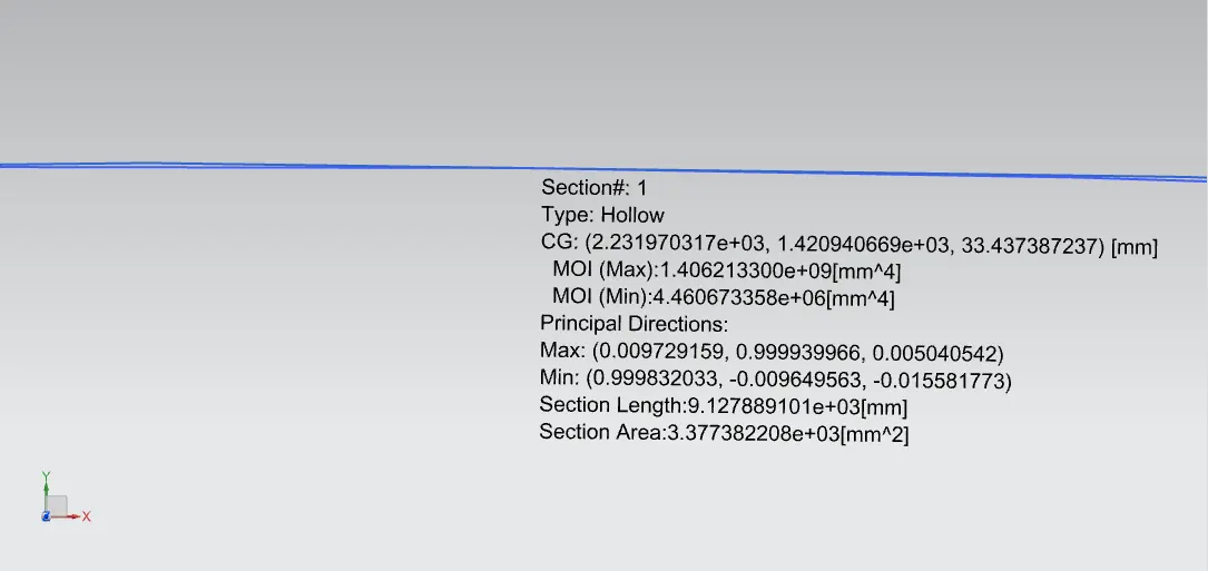
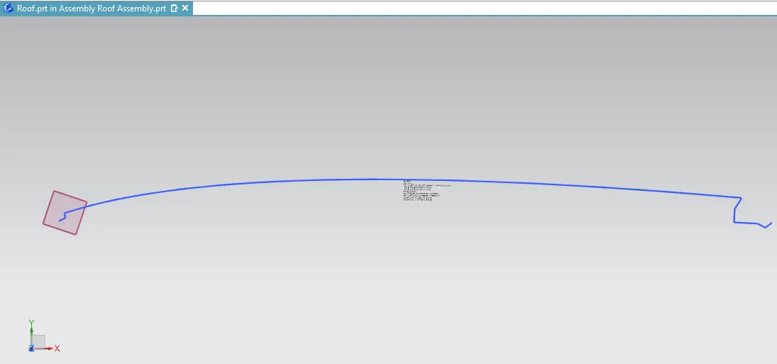
MOI FOR ROOF SURFACE :
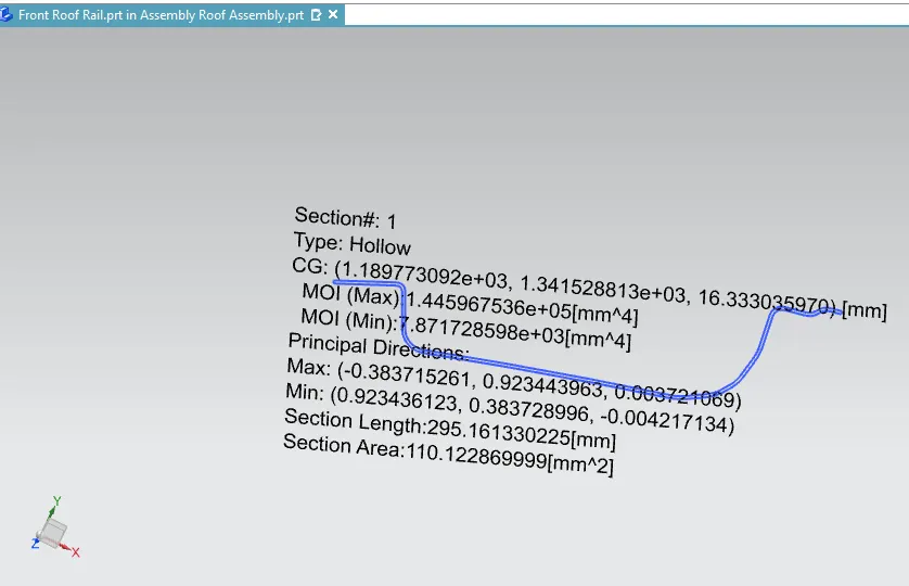
MOI FOR FRONT ROOF RAIL:
MOI FOR REAR ROOF RAIL:
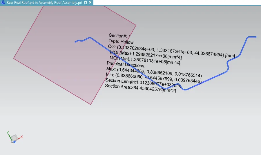
MOI FOR REINFORCEMENT CENTER ROOF RAIL:
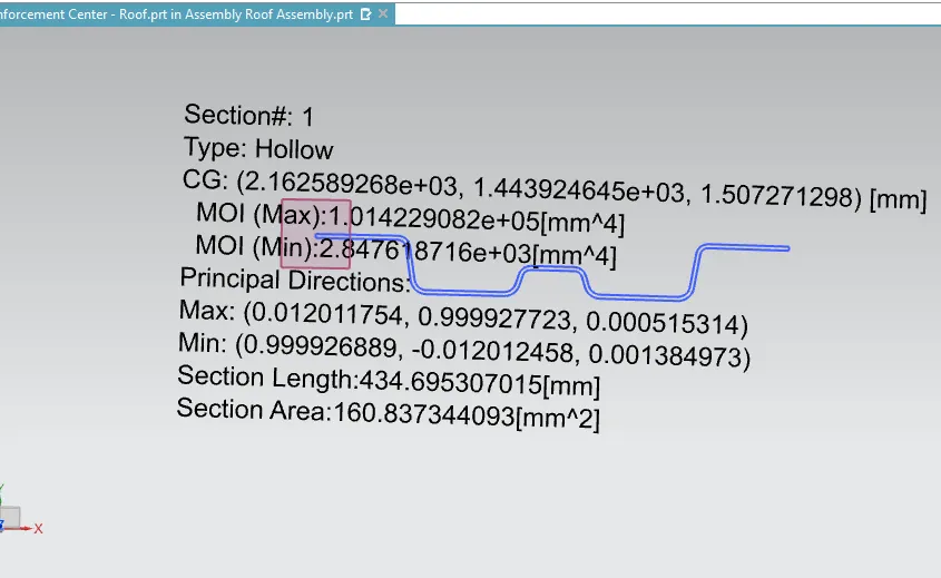
MOI FOR INNER ROOF RAIL OR BOW ROOF 3
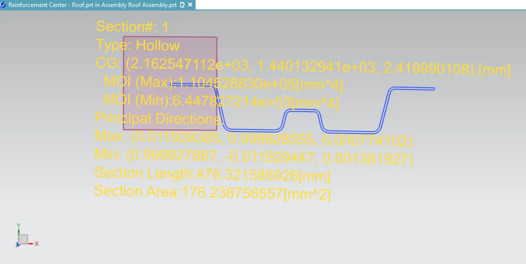
MOI FOR REINFORCEMENT CUM INNER ROOF RAIL:
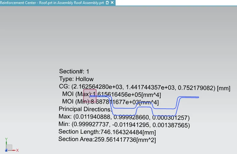
MOI FOR BOW ROOF - 1
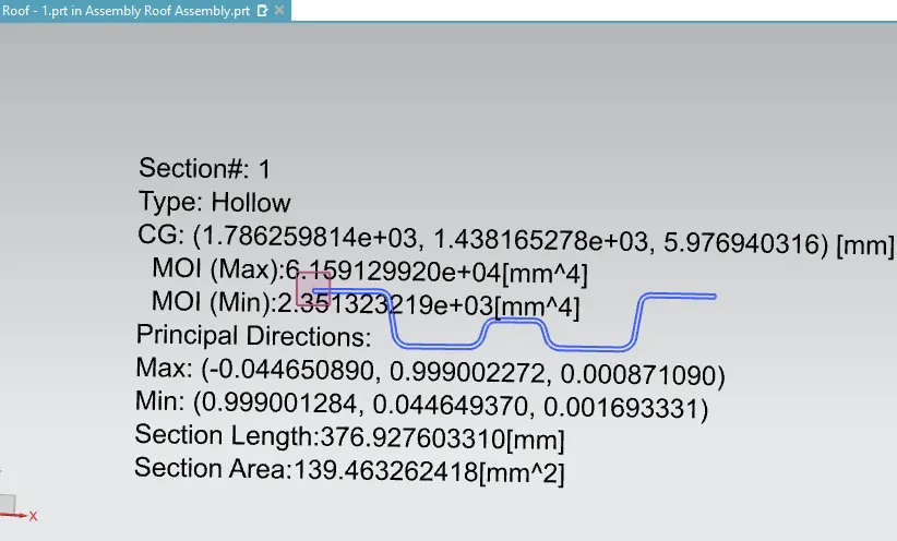
MOI FOR BOW ROOF - 2
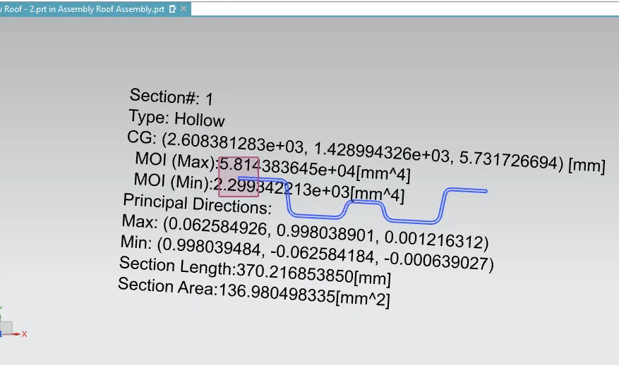
Draft Analysis Roof Assembly:
1. Draft Analysis is most important thing for automotive product desigining,because this method only revil for correct angle of produt dimensions and design constructions.
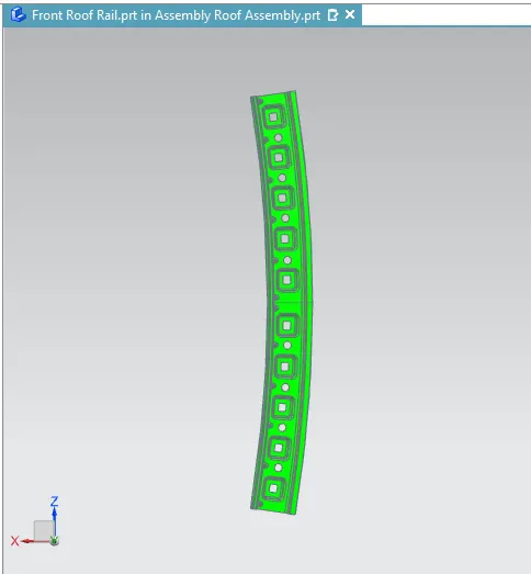
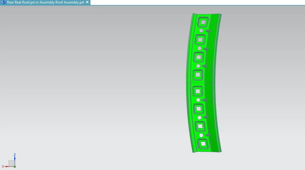
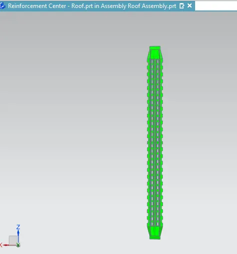
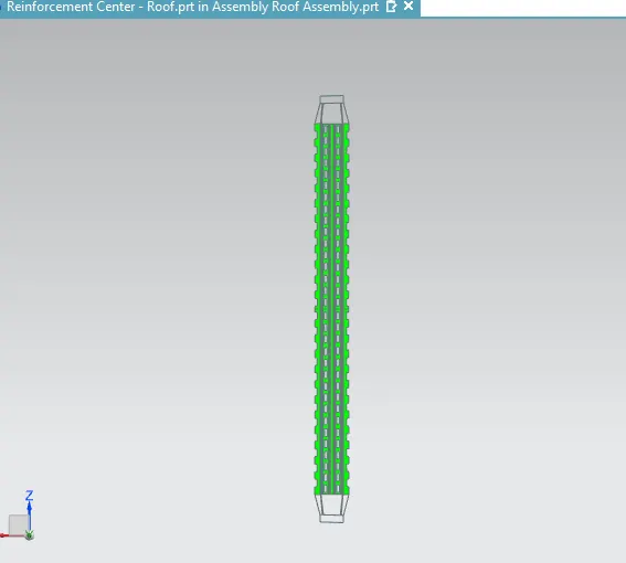
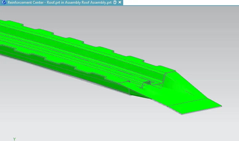
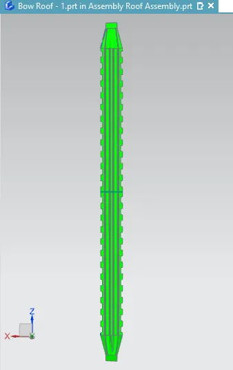
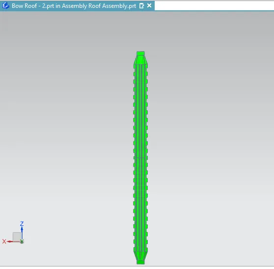
2.Select and consider the Roof click on the draft analysis command open the window and select the face on Roof and select the vector .in this product design we have to consider the vector is tooling Axis direction.So select the tooling Axis.Now we have input the Tooling Axis angle value .Every product desiging the minimum tooling axis angle is Minimum 7 deg ,So Enter the 7 deg and say ok.
Some color verition are created in the inner panel product.They are ,
1. 0 to 7 Deg - Yellow color.
2. 7 to >7 Deg - Green Color.
3. 0 to -7 Deg - Blue Color.
4. -7 to < -7 Deg - Red Color.
Now the inner Panel have Green Color.So we have identify the Draft angle for Minimum 7 Deg.
DRAFT ANALYSIS FOR ROOF SURFACE:
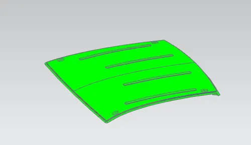
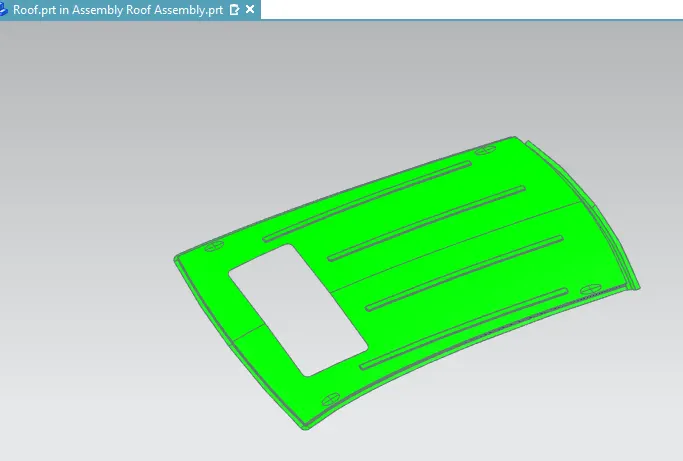
DRAFT ANALYSIS FOR FRONT ROOF RAIL :
DRAFT ANALYSIS FOR REAR ROOF RAIL:
DRAFT ANALYSIS FOR REINFORCEMENT CENTER ROOF:
DRAFT ANALYSIS FOR BOW ROOF - 1:
DRAFT ANALYSIS FOR BOW ROOF - 2:
DRAFT ANALYSIS FOR BOW ROOF - 3: