Roof Crush Analysis on Neon BIW
Aim
To make Roof crush setup on Neon BIW Assembly
Understand conditions applied for Roof crush
Simulate and obtain results
Analyze the results and conclude
Objective
Roof Crush - BIW
Import
• Car
• Impactor
Transforms
• This will require (in order)
• A 180° rotation about the global z-axis with the point opposite to C as base point
• A 5° rotation about the axis through axis AB
• A 25° rotation about the axis through axis AC
• A translation to put point A at global ( -3500.00, 584.822, 1343.06)
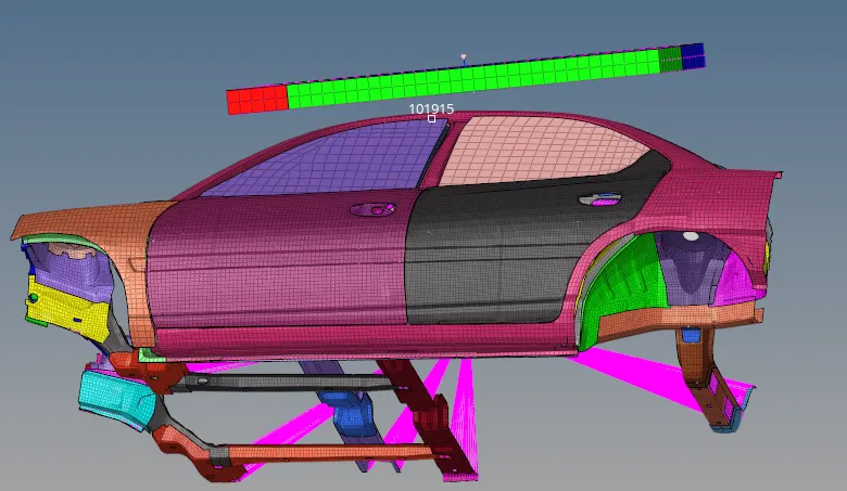
Reference image ( Full Vehicle Model )
Interfaces
• Create a Type 7 contact interface between the impactor and the car
• choose an appropriate stiffness definition
• choose an appropriate minimum gap
• change the coefficient of friction to 0.2
• choose the appropriate friction penalty formulation
• Save the data from the interface to the time history file.
Boundary condition
keep the suspension shock tower nodes locked in Z.
Impactor Boundary Conditions
• The impactor assembly contains a spring attached for stability. Create a BCS
collector to fix the free end of the spring.
• Create a moving SKEW to define the direction normal to the impactor’s
face.
• Create a BCS collector to guide the master node of the impactor rigid body
so that it is free to translate normal to the face of the impactor, but is fixed
in all other DOFs.
Imposed Displacement
• Impose the velocity of the impactor starting from 0 mm/s at t = 0. The
displacement of the impactor should be 200 mm @ 200 ms.
• Avoid abrupt changes in the acceleration of the impactor.
Control Cards
• /ANALY card
• /DEF_SHELL card,
• /DEF_SOLID card, and
• /IOFLAG card
• /SPMD card
• /TITLE card
Engine File
• Use a constant nodal time step
• Print time history every 0.0001 seconds
• Solve for 200 ms
• Create an animation file every 0.005 seconds
Include selected output in animation files:
• Elemental Energy
• Elemental equivalent plastic strain
• Elemental hourglass energy
• Elemental von Mises stress
• Nodal added mass
• Turn on parallel arithmetic
Solution and Results Post Processing
• Run the model
• Plot force vs. displacement. Check that the FMVSS 216 target load of
47,000 N (= 3 * GVW) has been met.
• Plot the energy vs. time curves
Click here for the models
Interfaces
• Create a Type 7 contact interface between the impactor and the car
• choose an appropriate stiffness definition
• choose an appropriate minimum gap
• change the coefficient of friction to 0.2
• choose the appropriate friction penalty formulation
• Save the data from the interface to the time history file.
Boundary condition
keep the suspension shock tower nodes locked in Z.
Impactor Boundary Conditions
• The impactor assembly contains a spring attached for stability. Create a BCS
collector to fix the free end of the spring.
• Create a moving SKEW to define the direction normal to the impactor’s
face.
• Create a BCS collector to guide the master node of the impactor rigid body
so that it is free to translate normal to the face of the impactor, but is fixed
in all other DOFs.
Imposed Displacement
• Impose the velocity of the impactor starting from 0 mm/s at t = 0. The
displacement of the impactor should be 200 mm @ 200 ms.
• Avoid abrupt changes in the acceleration of the impactor.
Control Cards
• /ANALY card
• /DEF_SHELL card,
• /DEF_SOLID card, and
• /IOFLAG card
• /SPMD card
• /TITLE card
Engine File
• Use a constant nodal time step
• Print time history every 0.0001 seconds
• Solve for 200 ms
• Create an animation file every 0.005 seconds
Include selected output in animation files:
• Elemental Energy
• Elemental equivalent plastic strain
• Elemental hourglass energy
• Elemental von Mises stress
• Nodal added mass
• Turn on parallel arithmetic
Solution and Results Post Processing
• Run the model
• Plot force vs. displacement. Check that the FMVSS 216 target load of
47,000 N (= 3 * GVW) has been met.
• Plot the energy vs. time curves
Given Model
Car ; Impactor
Physics of Roof Crush
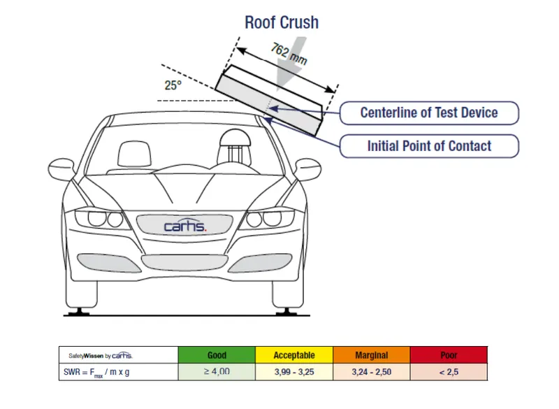
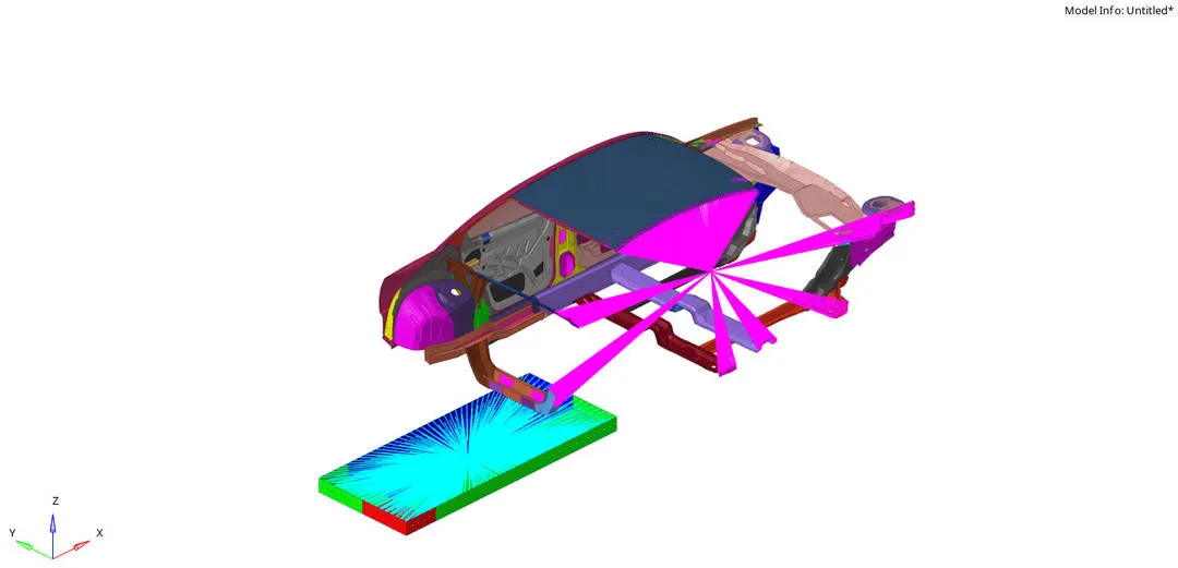
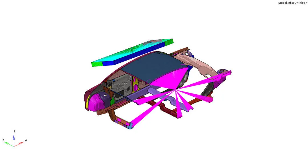
After Rotation and Translation Operation
Transformations
• This will require (in order)
• A 180° rotation about the global z-axis with the point opposite to C as base point
• A 5° rotation about the axis through axis AB
• A 25° rotation about the axis through axis AC
• A translation to put point A at global ( -3500.00, 584.822, 1343.06)
Interfaces
Type 7 - Self Impact Interface was given with Recommended Properties
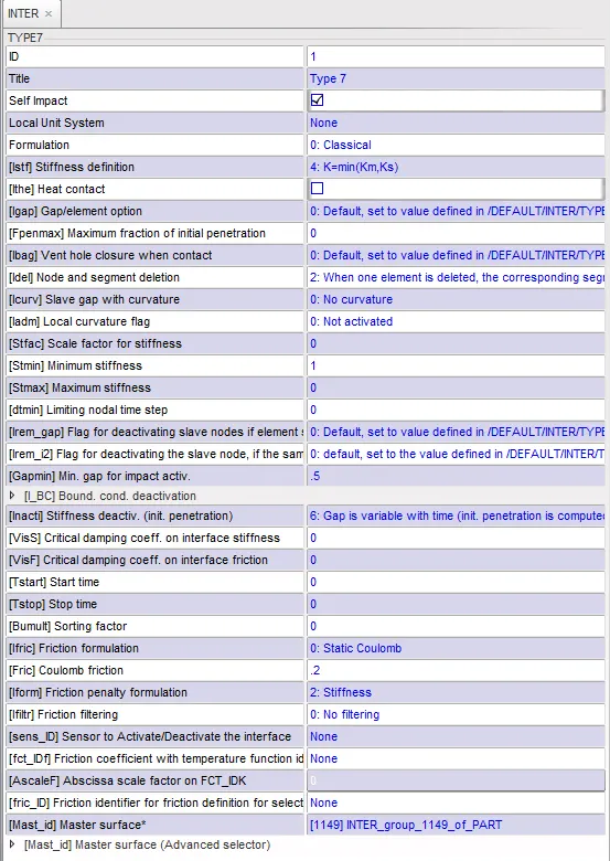
Self Impact
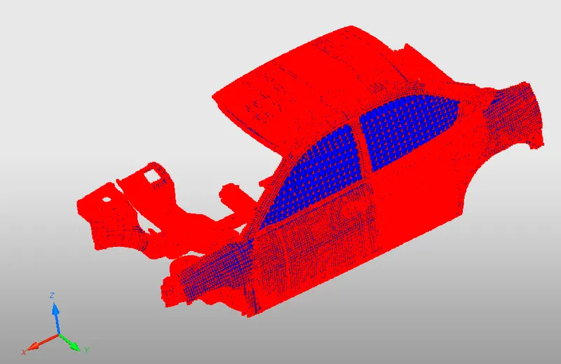
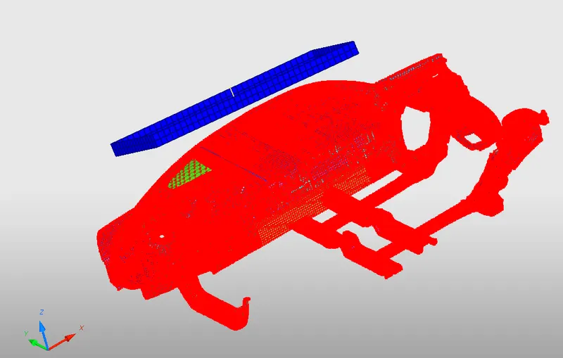
Interface between Impactor and Car
Master Nodes - Impactor ; Slave Nodes - Car
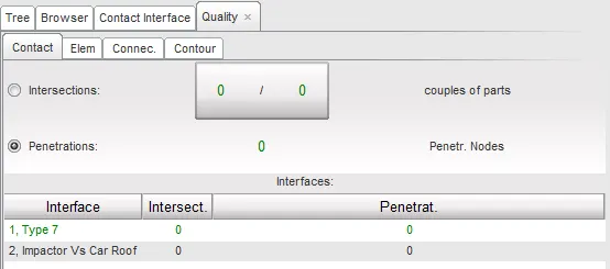
Check Connectivity
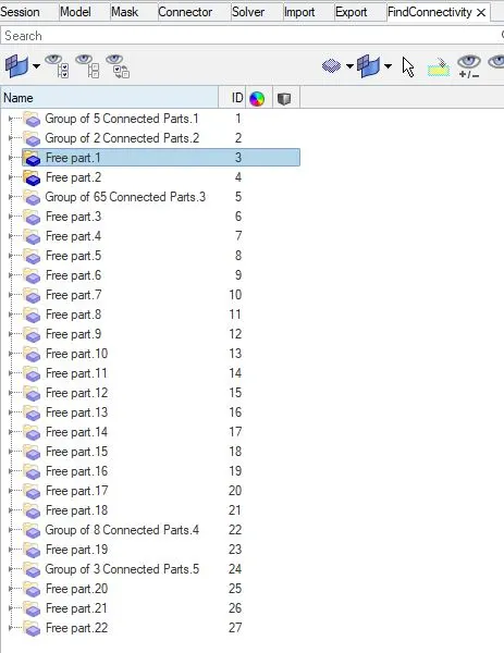
We have to make sure all parts are connected and there is no free floating part, if so that part alone will move separately in their own degree of freedom during the simulation
Floating parts can be connected using spring 2N element and P13_SPR _BEAM Properties is created for the spring element or use Type 2 spring moving parts
Rigid body Boundary conditions
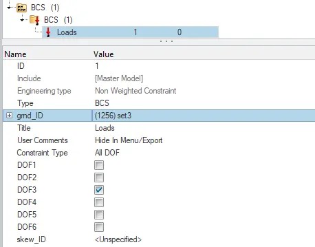
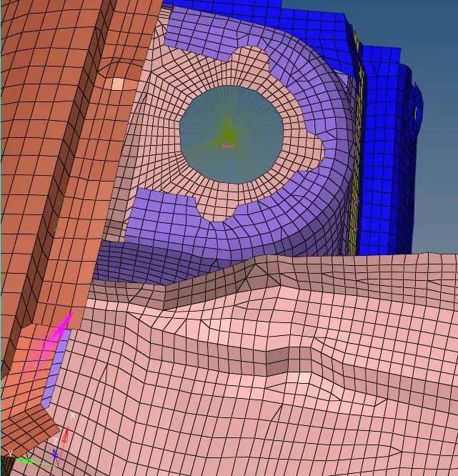
kept the suspension shock tower nodes locked in Z-axis
Impactor Boundary Conditions
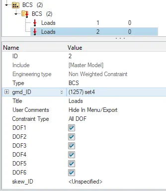
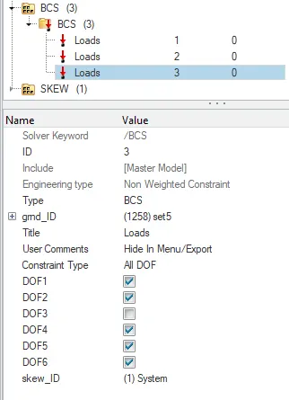
The impactor assembly contains a spring attached for stability. Create a BCS collector to fix the free end of the spring.
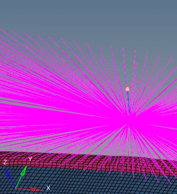
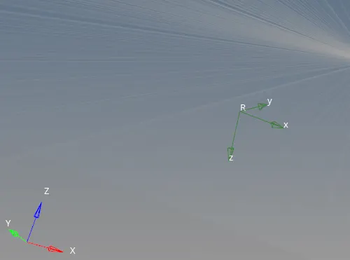
Created a moving SKEW to define the direction normal to the impactor’s face.
Created a BCS collector to guide the master node of the impactor rigid body so that it is free to translate normal to the face of the impactor, but is fixed in all other DOFs.
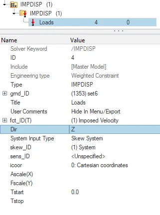
Imposed Displacement
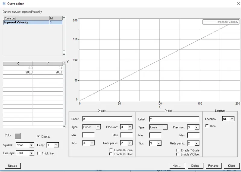
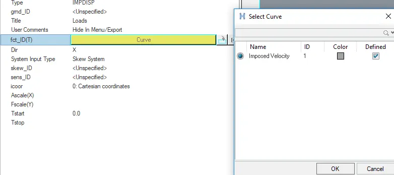
Impose the velocity of the impactor starting from 0 mm/s at t = 0. The displacement of the impactor should be 200 mm @ 200 ms

Control Cards
In ENG_ANIM_ELEM card following were selected
Elemental Energy
Elemental equivalent plastic strain
Elemental hourglass energy
Elemental von Mises stress
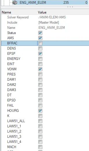
These outputs can be seen in h3d file
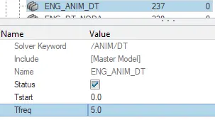
In ENG_ANIM_DT T_freq value given as 5.0
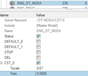
In ENG_DT_NODA CST was selected
Used a constant nodal time step
Create an animation file every 0.005 seconds
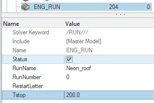
In ENG_RUN card T_stop vlaue was given
Time to solve given as 200 ms
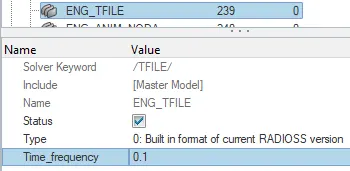
In ENG_TFILE Time_frequency was given
To print time history every 0.0001 seconds converted to 0.1ms was created
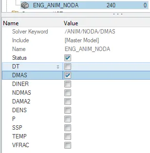
In ENG_ANIM_NODA DMAS was slected
/ANALY card
In Analysisflag control card
Turned on parallel arithmetic
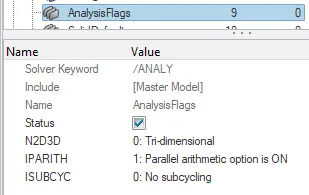
N2D3D =0; ≠ 0;for example; for axisymmetrical and plane strain analysis, the elements must be defined in YZ plane and their normals have to be in the positive x-position; but in this case z is normal direction; so default value
IPARITH = 1 ; Irrespective of number of processors used; arithmetic calculations will be done
If parallel arithmetic flag is set ON, the same numerical results will be obtained irrespective of the number of processors used. This result is not guaranteed in case of incompatible kinematic conditions in the model.
Sub Cycling : may be used in cases where some solid parts have a very low time step compared to the shell structure and the shell structures represent a significant percentage of the number of elements; no used in this case.
/DEF_SHELL card
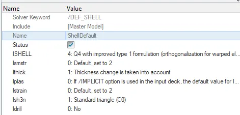
ISHELL -Q4 Element formulation (orthogonalization for warped elements) best combination of cost and accuracy
Ismstr - 2; Specify small or large strain formulation ;small strain formulation due to geometric non linearities
Ithick - 1; thickness parameter is taken into account according to plastic deformation; faster calculation
Iplas - 0;Choose method for calculating post-yield strains ; Implict analysis is not used
Istrain - Select element formulation for 3-noded shells
/DEF_SOLID card
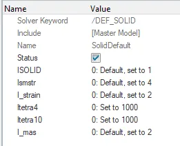
Isolid ;Choose hex element formulation
Ismstr ;Specify small or large strain formulation
/IOFLAG card - Input Output Flags
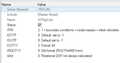
IPRI ; Starter output printout flag
IOUTP ;Output a STY model file flag
OUTYY; STY file output format flag
IROOTYY: STY file name flag
IDROT;Force computation of rotational DOF flag
/SPMD card - SPMD parameters for Hybrid Massively Parallel Program (HMPP) computation
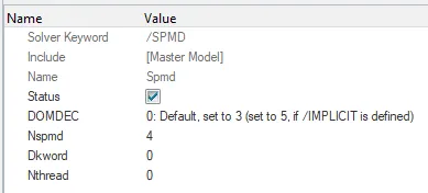
DOMDEC ;Type of domain decomposition for SPMD (single program), multiple data version
Nspmd ;Number of SPMD domains
/TITLE card
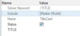
-Title to be displayed
Post Processing
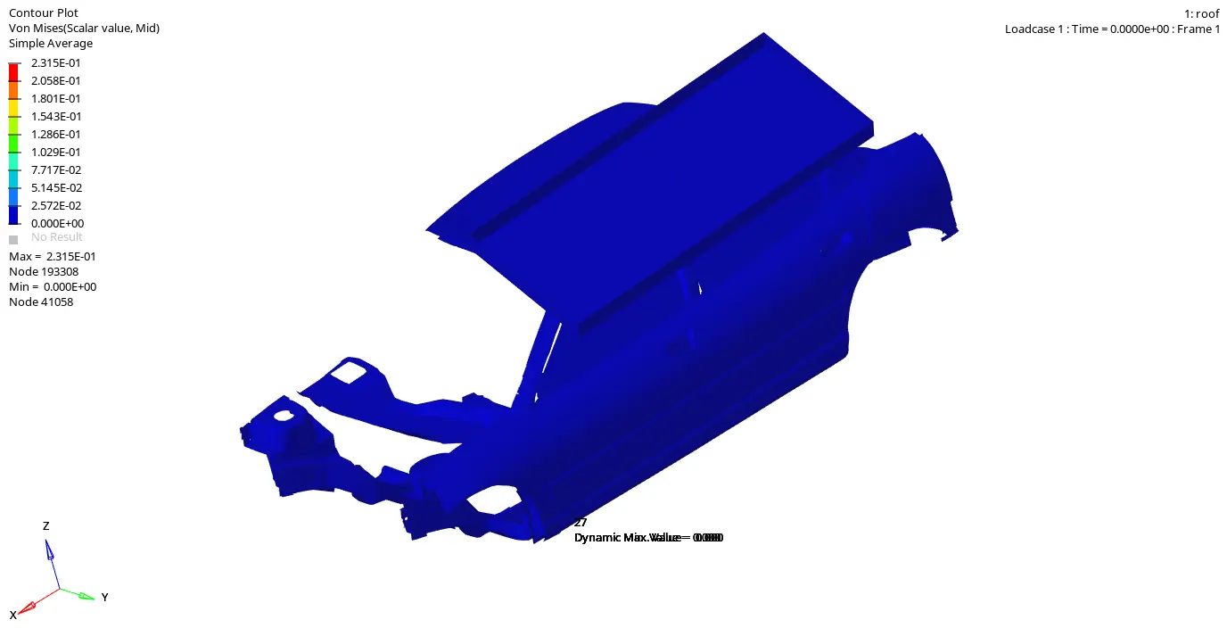
Maximum Vonmises Stress = 0.231Gpa
There are connectivity issues which can be rectified by connecting floating parts using Type 2 Spring
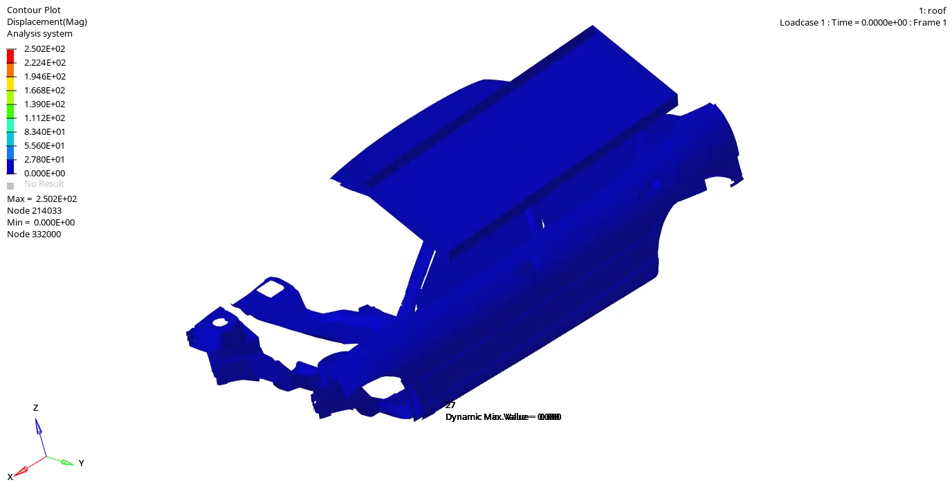
Maximum Displacement =250mm
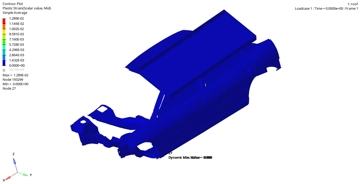
Maximum Plastic Strain = 0.0128
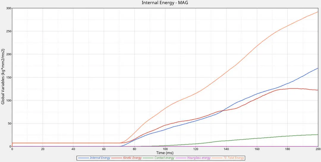
Energies Plot
Inference
- Quasi-static load means the load is applied so slowly that the structure deforms also very slowly (very low strain rate) and therefore the inertia force is very small and can be ignored. A dynamic load, on the other hand, casues a structure to vibrate and the inertia force is big enough and must be considered.
- Initially Kinetic energy can be seen increasing at the point 66ms there was contact of impactor with the roof.
- Maximum Kinetic Energy can be seen at 200ms of 295 kg-mm^2/ms^2 which is quiet high.
- Maximum Internal Energy can be seen at 200ms of 145 kg-mm^2/ms^2 starting from 65ms.
- Contact energy has started from 100ms there was slave node interference and 30kg-mm^2/ms^2 of energy was used.
- Total Energy is the sum of all energies and total energy at 200ms is 295 kg-mm^2/ms^2
Force Vs Displacement
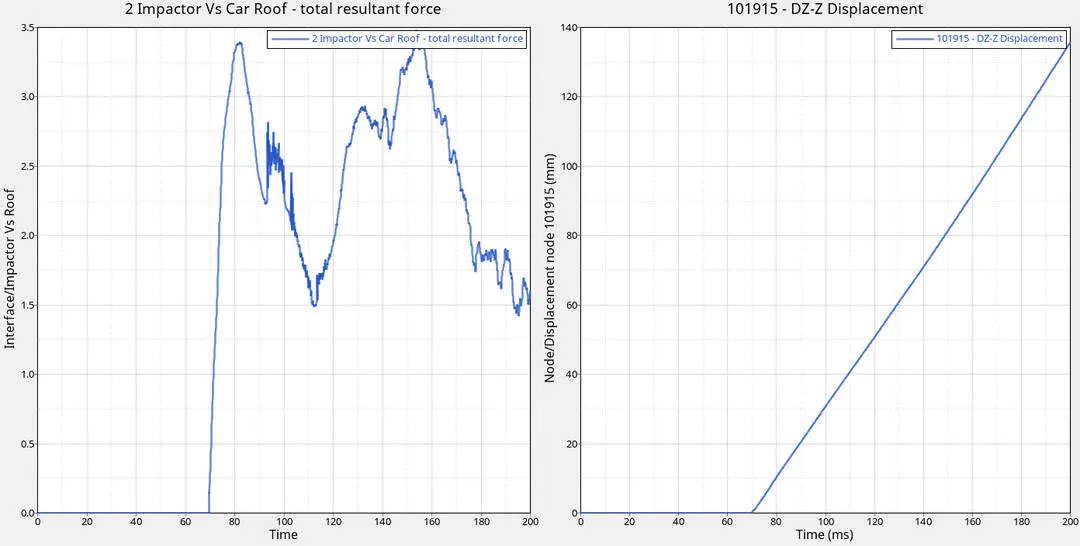
- About 3.4kN of force exerted on roof by the impactor
- The 101915 node has displaced 136mm in the local z-axis since there is clear deformation in the Roof Rail, there might be head injury to the head of occupant based on height
By using Math>Cross Plot Force Vs Displacement curve was generated
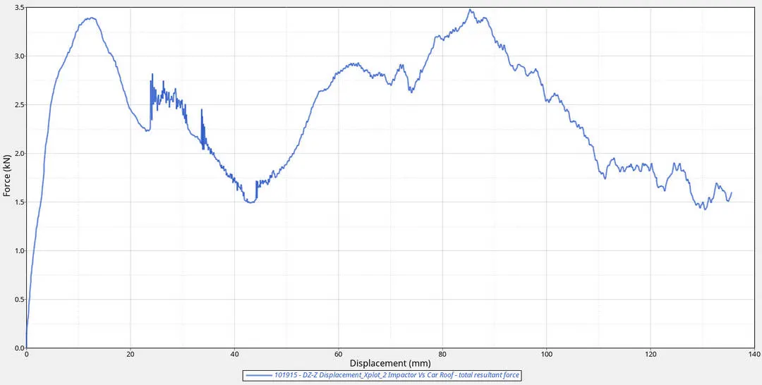
- Maximum Resistive Force is 3.5kN at 140mm of Node 101915
- According to FMVSS 216 Specified strength to weight ratio required a resistance force of 3 times GVW(Gross Vehicle Weight) to Protect the Passengers from the roof crash
- Weight of the model =174.8kg
- R.F = 3*Weight of model * acceleration due to gravity
- R.F= 3*174.8*9.81 =5144.36N = 5.14kN
- From accquired results 3.4kN is less than the calculated resistance force value
- Due to student version constraints unable run whole model as its 300k
- Results vary for Whole body

Results and Conclusion
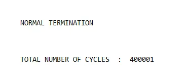
- Energy error and mass error is within acceptable range
- Roof crush was done according FMVSS standard based on student version limitations
- Roof panel strength and stiffness can be improved
- Support panel can be attached for support in way it can endure more damage as to before it reaches occupants
- Attatchments of Roof panel like B -Pillar strength can be increased by using alloys
- Support attatchements can also be given
References
https://web.iitd.ac.in/~achawla/course_pdfs/4.%20MEL736/11-Crash_Safety_practices.pdf
https://designgyan.com/srp457/assets/images/papers/DG_17541091_1_Crash_Book_October_24_2017.pdf
https://www.nhtsa.gov/sites/nhtsa.dot.gov/files/tp214p-01.pdf