Roof challenge
Aim - To design the roof asssembly of a car
About -
Wha is roof assembly?
A car roof is an integral part of the car which provides cover to passangers inside the car from elements of nature like Sunlight in summers, rain, and helps to maintain the temperature inside the car. It is designed keeping in mind various factors like heat distortion criteria, snow loading criteria and vehicle turnover in case of accidents. A car roof is an assembly of number of different components which together constitute a car roof. These are Outer roof panel, Front roof rail, Rear roof rail, bow roofs and centre roof reinforcements. All these components are provided to give strenth to the car roof.
Fig - Roof of a car (Highlighted portion)
Compnents of a car roof -
1. Roof panel
2. Bow
3. Inner side rail
4. Drip rail
5. Front roof rail
6. Rear roof rail
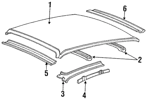
Fig - Components of a car roof
Front roof rail - The deisgn of front roof rail is done keeping in mind various considerations like thickness of wind shield glass, adhesive thickness, sealant thickness along the perimeter of wind shield glass, visibility criteria for the driver and head clearance for comfort.
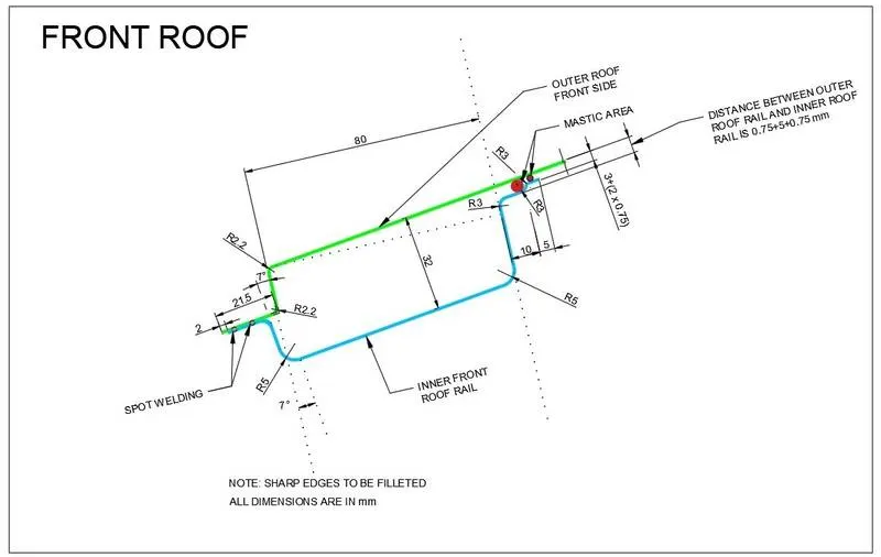
fig - Master section of front roof rail
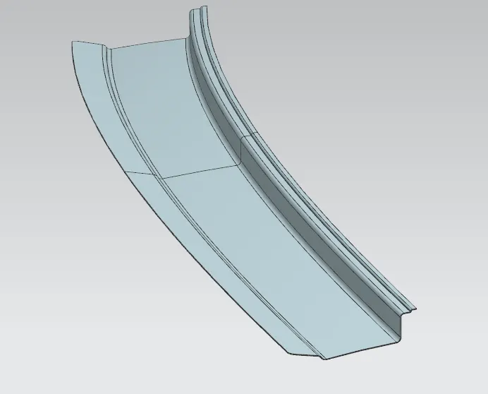
fig - front roof rail CAD model
Rear roof rail - The design of rear roof rail includes factors like rear head clearance , rear visiblity criteria and installation space for back door assembly.
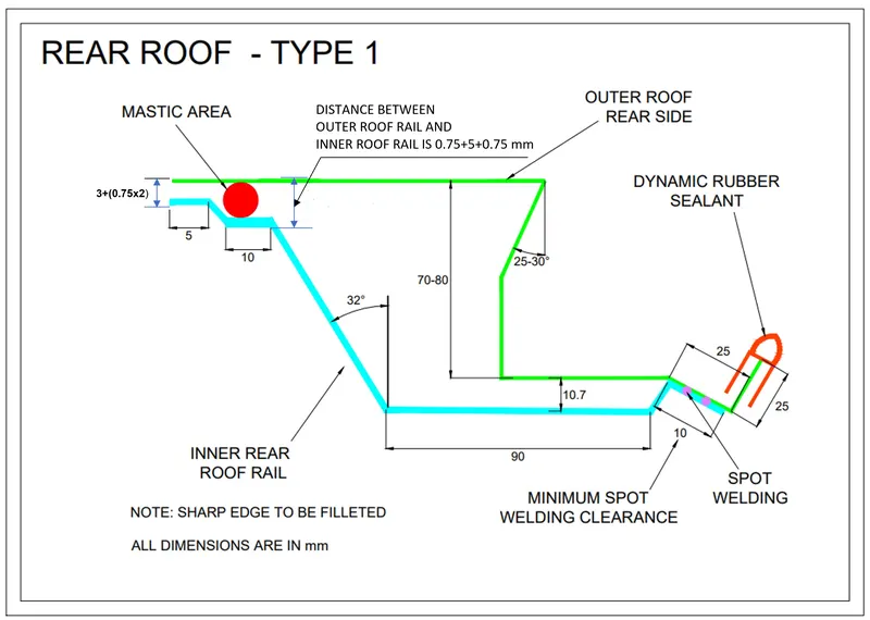
Fig - Rear roof rail master section
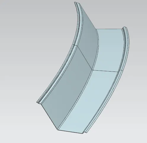
Fig - Rear roof rail CAD model
Bow roofs - Bow roofs have a specific work of adding strength to the roof. These are provided where the area on the roof is flatter, since flatter gemetry has less strength than curvature geometry. for smaller length cars the number of bow roofs vary from 1 to 2, or even sometimes only centre bow roof reinforcemnet is provided which does the work. The longer the car more will be the flatter surface and hence more the number of bow roofs required for strengthening the roof of a car. The connection between bow roof and roof panel is through mastics.
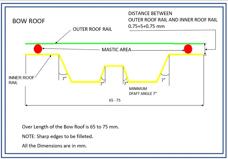
Fig - master section of Bow roof
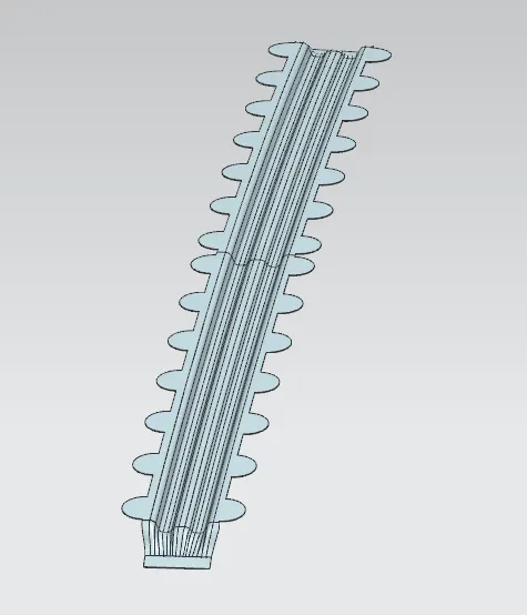
Fig - Bow roof CAD model
Centre roof reinforcement - It serves the same goal as of bow roofs and is wider than bow roof. It is intalled as a bridge on B-Pillars of a car.
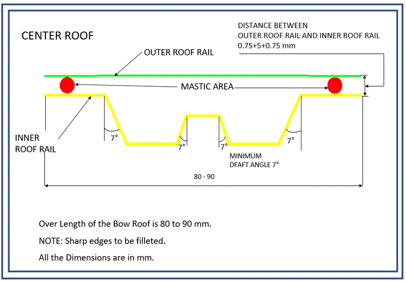
Fig - centre roof master section
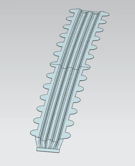
Fig - centre roof CAD model
Assembly of roof -
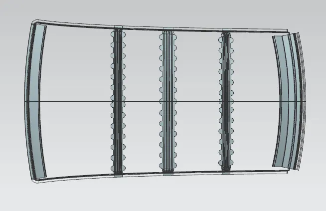
Fig - Roof Assembly
The entire roof assembly after completion of deign and feezing the design is subjected to diffrent design citerias for testing it under different loading and temperature conditions. Here, the roof assembly is subjected to two criterias for testing the design - Heat distorton criteria and Snow loading criteria.
Heat distortion criteria - Roof of a car is exposed to constant and direct sunlight on a sunny day.This leads to increase in temperatures of the material of which the roof is made of. With increase in temperatureundesirable effects like thermal distortion of roof can occur. Thermal distortions can affect the strength of the car roof to withstand loads at different conditions. For this to keep in check , the designed roof assembly is subjected to heat or thermal distortion criteria. It tests the car roof on perimeters which decide if the roof is fit for installation or not. With the help of this study called as curvature study of roof, the positions of bow roofs are decided to provide strength while factoring in thermal distortion condition. Below is the criteria in the form of Bow-roof prediction formula.
W = [1.73 x 10^(-3) x L] + [1.85 x 10^(-8) x (R^2)/t] + [ 1.10x10^(-3) x l] - 2.68
Judgement Condition : OK< 2.7
Where
L = Roof Length in X-Direction[mm](Roof dimension in 0-Y)
R = Roof curvature
R = 2(Rx*Ry)/(Rx+Ry)
Rx = X curvature
Ry = Y curvature
t = Roof plate thickness [mm]
l = Bow Roof Span [mm]
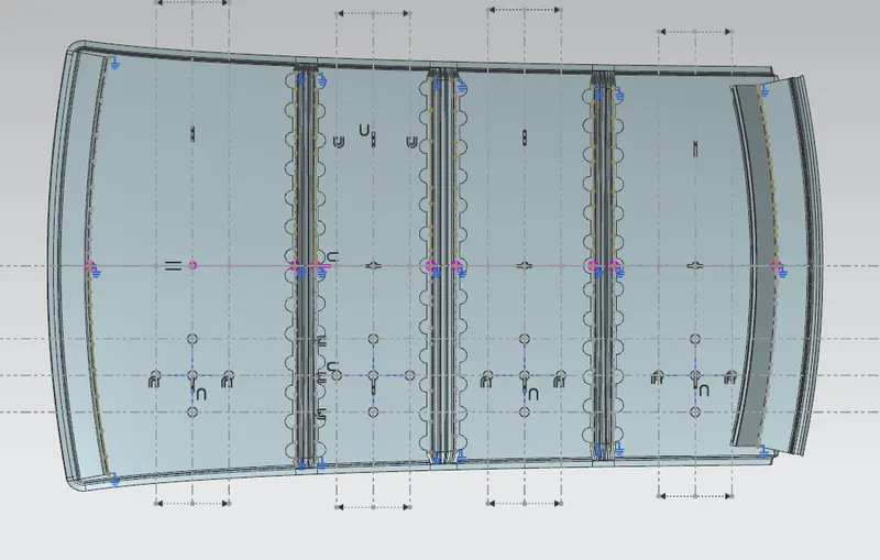
Fig - Sketch for heat distortion criteria
| S.No | Bows | Rx | Ry | R | I | L | t | W | Remark |
| 1 | Fr & 1st | 5671.762 | 3150.607 | 4050.947 | 558 | 2023.42 | 0.75 | 1.8385 | Ok |
| 2 | 1st & centre | 4743.815 | 7116.455 | 5692.812 | 278.185 | 2023.42 | 0.75 | 1.2058 | Ok |
| 3 | centre & 2nd | 3961.279 | 10663.906 | 5776.707 | 319.152 | 2023.42 | 0.75 | 1.9941 | Ok |
| 4 | 2nd & RR | 3260.29 | 14719.838 | 5338.220 | 348.232 | 2023.42 | 0.75 | 1.9059 | Ok |
Snow loading criteria - This condition is imposed on roofs which are subjected to static or dead loads as a result of accumulation of snow on the car roof. For the roof to be able to withstand the dead load of snow, it is tested for this criteria called as Snow load prediction formula.
Qr = [Iy x t2] / [α x s x [(Rx + Ry)/2]2 x 10-8]
Where
α = My x Lx2 x 10-12 , My = Y(Ly-Y)
Judgement condition = Qr ≥ 3.1
250 ≤ s ≤ 380
t = Roof plate thickness [mm]
Ly = Distance between the front and rear roof Rails on the Vehicle along with 0Y[mm]
Length of Roof panel with the center point between Roof rail Front /Rear as the reference point of the front and the rear.
Lx = Distance between the Left and Right end of the roof on the Roof BOW [mm]
Width of the roof panel exposed on the surface.
Y = Distance front Front Roof Rail to Roof BOW[mm]
s = Distance for which Roof BOW bears divided load [mm]
s = L1/2 + L2/2
Iy = Geometrical moment of inertia of Roof BOW (Y cross-section )[mm4]
Rx = Lateral direction curvature radius of roof panel Y cross-section on Roof BOW [mm]
Roof panel curvature Radius of the Length Lx in Front view
Ry = Longitudinal Direction curvature radius of the Roof panel X cross-section on Roof BOW [mm]
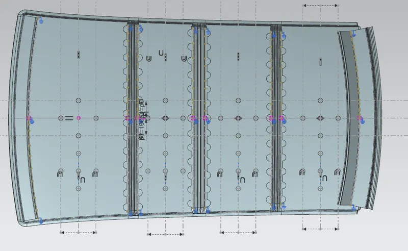
Fig - Sketch of Snow loading criteria
Section inertia anlysis of bows and centre roof -
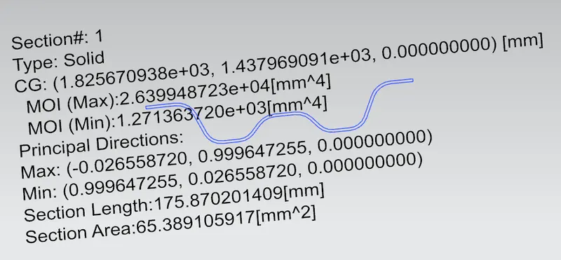
Fig - Bow roof 1 analysis
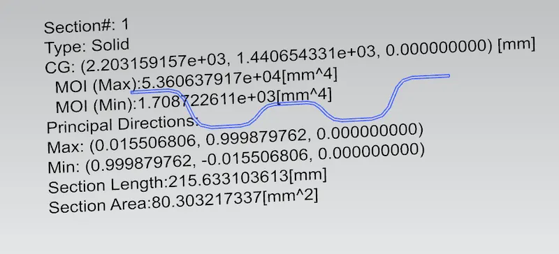
Fig - Centre roof reinforcement analysis
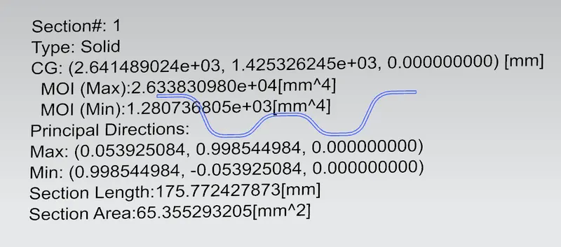
Gig - Bow roof 2 analysis
| S.No | Bows | Iy | My | α | Lx | Ly | y | L1 | L2 | s | Rx | Ry | t | Qr | Remark |
| 1 | Fr & 1st | 1271.263 | 882982.36 | 1.11 | 1121.55 | 2023.42 | 636.777 | 575.761 | 314.468 | 445.114 | 4231.478 | 3103.816 | 0.75 | 10.76 | Ok |
| 2 | 1st &Ctr | 1708.76 | 620846.31 | 0.716 | 1074.61 | 2023.42 | 377.115 | 314.468 | 375.855 | 345.161 | 3835.939 | 7079.27 | 0.75 | 13.05 | Ok |
| 3 | Ctr&2nd | 1280.73 | 694961.05 | 0.771 | 1053.43 | 2023.42 | 438.477 | 375.855 | 445.302 | 410.578 | 4282.895 | 11183.13 | 0.75 | 3.805 | Ok |
Draft Analysis -
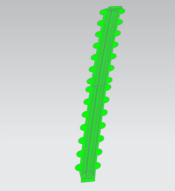
Fig - Bow roof 1
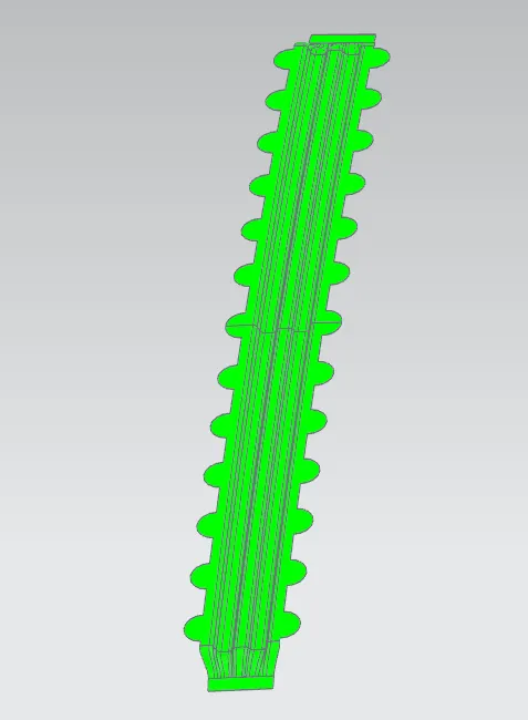
Fig - Bow roof 2
Fig - Centre roof
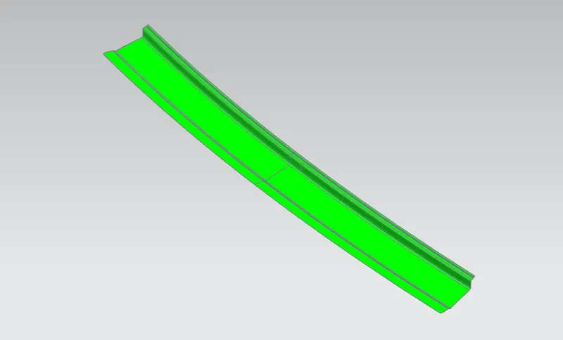
Fig - front roof rail
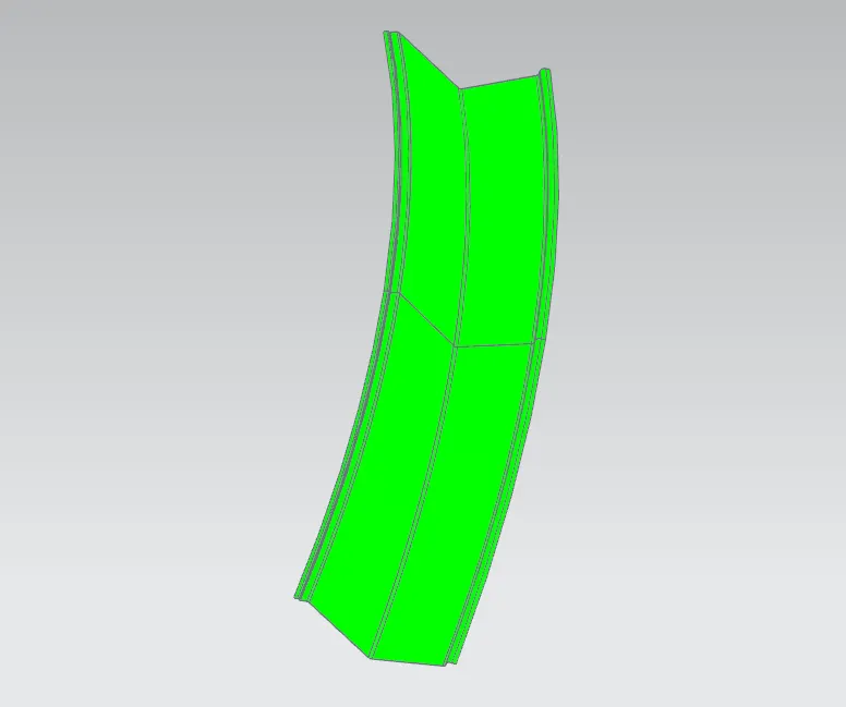
Fig - rear roof rail
Hence, all the components of the roof assembly are drawable with minimum minimum angle of 7 degrees.
Conclusion - Design of roof assembly is done with all necessary design criteria being sattisfied.