Roof challenge
OBJECTIVE:-
- To design a car roof by extracting the styling surface from styling team with essential flanges and reinforcement namely ditch Area, front roof Rail, Rear roof rail, bow roofs, center roof rail.
- Do a curvature study on the roof and perform calculations for heat distortion and snow load criterion to determine and justify the position of the bow-roofs.
- perform draft analysis for Bow roofs, center roof rail, front roof rail, rear roof rail.
INTRODUCTION:-
an automobile root or car top is the portion of an automobile that sits above the passenger compartment, protecting the vehicle occupants from sun, wind, rain, and other external elements. Convertible roofs, roof modules, roof modules, hardtops, sunroofs, T-tops, Targa tops, vinyl roofs are the different variants in an automobile.
DESIGN PROCEDURE:-
He front roof rail and the rear roof rail are the components, where the front and rear sides of the roof are attached, while the other three reinforcement gives enough strength.This assembly includes Roof Outer Panel, Front Roof rail, Rear Roof Rail, Center Roof rail, Bow Roof 1 and Bow Roof 2. while Front roof rail and rear roof rail is designed with the help of given master section.
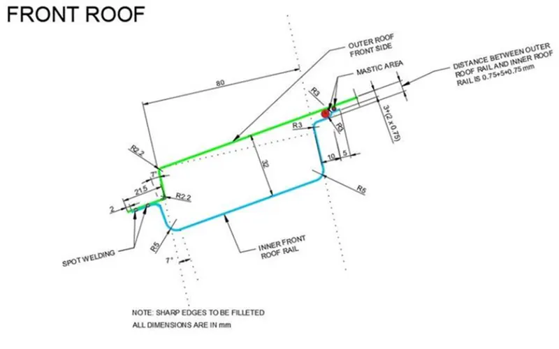
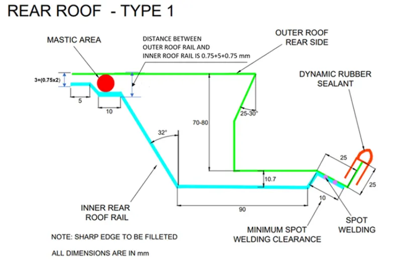
FRONT ROOF RAIL:-
- The front roof rails will be joining the wind shield, body side inner and other panel, so the front roots must be designed to have the visibility clearance for the wind shield.
- By considering the deep drawing of the part the front roof was designed to have the draft value of more than 5 degree.
- The front roof rail has the same offset surface for the ditch area where both will be connected using spot welds.
- The front roof rail was provided with embosses to increase the strength and stiffness of the rail.
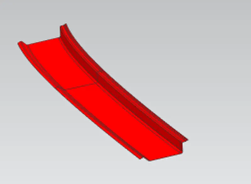
REAR ROOF RAIL:-
- The rear roof rail was designed by taking the back door clearance into consideration since the opening and closing of the back door will effect on the roof.
- The ditch area on the roof was connected with the rear roof by using the mastic sealant or spot welding.
- Spot welding will be used for joining the hinges of the back door with the roof.
- Embosses were added to increase the stiffness were and strength of the rail without affecting the heat room clearance.
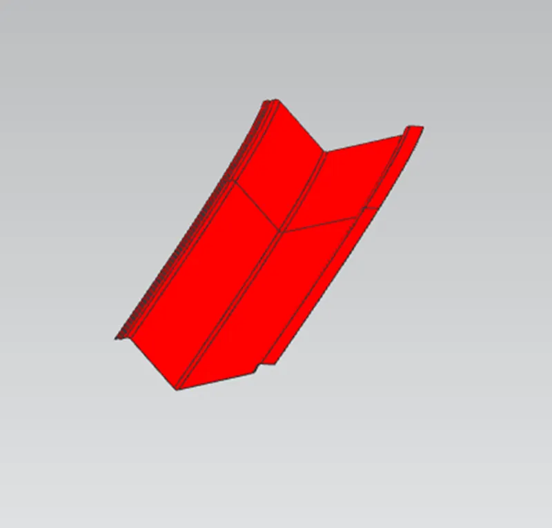
BOW ROOFS 1&2:-
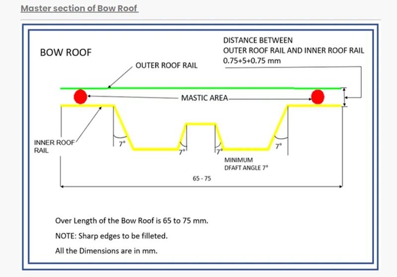
- All the bow roof rails were placed between the front and rear roof rails.
- Bow roof rails were added to increase the stiffness of the roof since it has the large flat surface.
- To increase the curvature result of the roof where it needs to withstand the heat distortion and snow load criteria the bow roofs were positioned as per the standards.
- The bow roofs were provided with mastic points since the joining process will be done using the mastic sealants.
- Spot welds also possible but it will damage the aesthetic appearance of the car roof.
- Embosses were also provided all over the bow roofs to increase the stiffness rapidly.
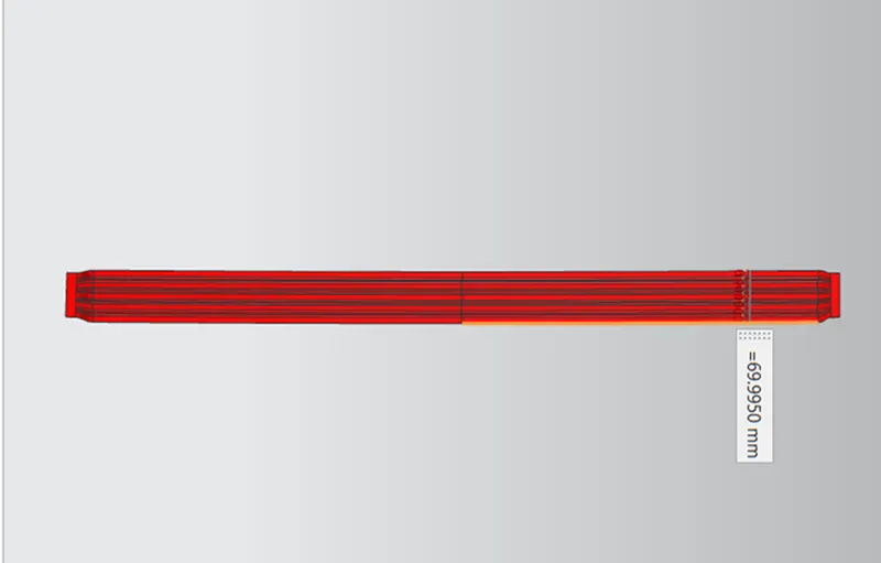
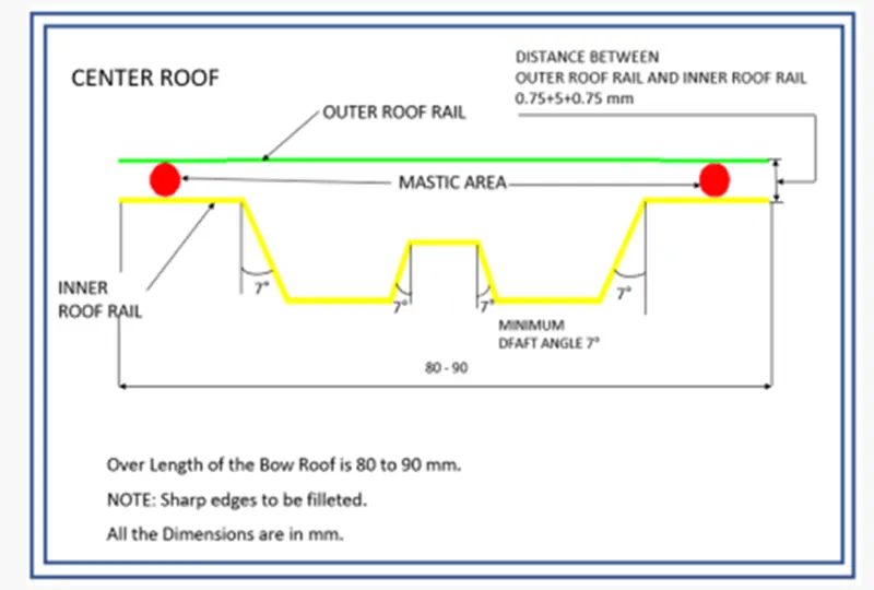
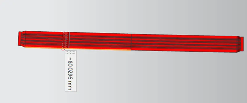
- The bow roof position needs to satisfy the head room clearance and draft analysis for deep drawing.
CENTRA ROOF RAIL:-
Heat Distortion Curvature Study:-
The heat distortion study plays an important role in sheet metal usage. Heat distortion temperature is a temperature limit above which material cannot be used for the structural applications. This study is used to predict the heat distortion temperature at where the material starts to soften when exposed to a fixed load at elevated temperature. In order to avoid bending or damages on the roof, based on the heat distortion temperature, this study will predict the bow roof position temperature, this study will predict the bow roof position which help to strengthen the roof.
Bow–roof prediction Formula
W = [1.73 x 10^(-3) x L] + [1.85 x 10^(-8) x (R^2)/t] + [ 1.10x10^(-3) x l] - 2.68
Judgement Condition: OK< 2.7> 3.1
Where,
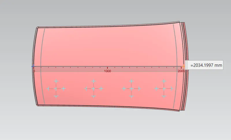
L = Roof Length in X-Direction[mm] (Roof dimension in 0-Y)
R = Roof curvature
R = 2(Rx*Ry)/(Rx+Ry)
Rx = X curvature
Ry = Y curvature
t = Roof plate thickness [mm]
l = Bow Roof Span [mm]
Judgment Condition
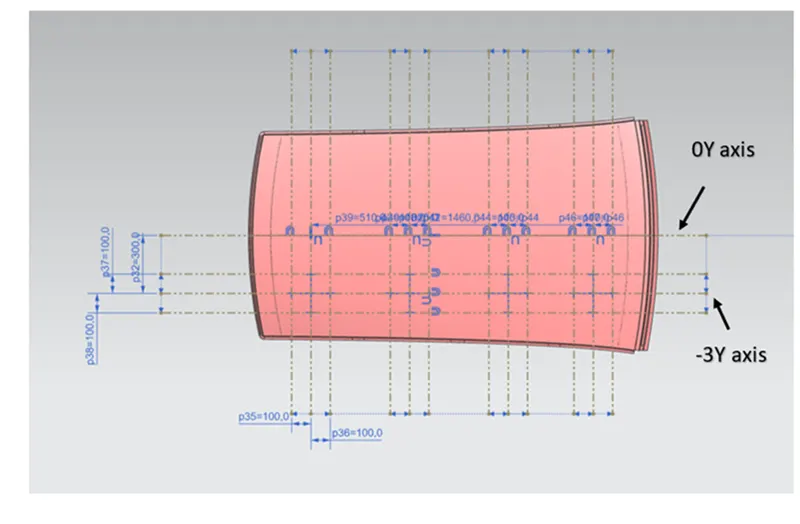
- From O-Y axis, at -3y about distance 300mm is drawn parallel on the perpendicular plane as shown in fig. after that 100 mm lines are offset to either side of -3Y line. Now center lines are drawn between each adjacent roof rail edges respectively. Intersection points are marked on the sketch and exit the sketch. Make all geometry in construction lines except the points.
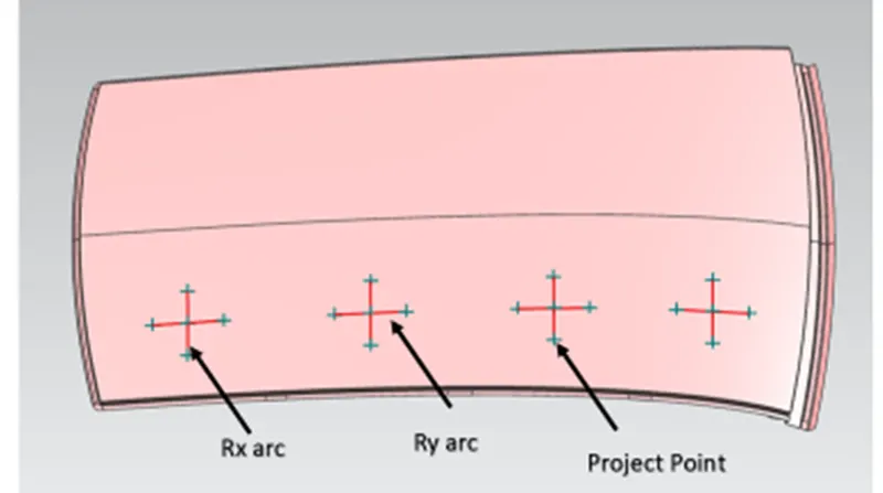
- Project the intersection points in the sketch to roof surface as shown in fig.
- Join the projected curves using arc curve and measure the minimum radius and linear dimension as follow and put into the formula to calculate W.
nY axis and intersection points
Project points on roof for Rx & Ry
Roof Length in X Direction

Snow Load Prediction on the Roof
Snow load prediction formula
Qr =[Iy x t2] / [α x s x [(Rx + Ry)/2]2 x 10-8]
Where,
α = My*Lx2*(10^-12)
My = Y(Ly-Y)
Judgement Condition,
Qr ≥ 3.1
250 ≤ s ≤ 380
t = Roof plate thickness [mm]
Ly = Distance between the front and rear roof Rails on the Vehicle along with 0Y[mm]
Length of Roof panel with the center point between Roof rail Front /Rear as the reference point of the front and the rear.
Lx= Distance between the Left and Right end of the roof on the Roof BOW [mm]
Width of the roof panel exposed on the surface.
Y = Distance front Front Roof Rail to Roof BOW[mm]
s= Distance for which Roof BOW bears divided load [mm]
s = L1/2 + L2/2
Iy = Geometrical moment of inertia of Roof BOW (Y cross-section )[mm4]
Rx = Lateral direction curvature radius of roof panel Y cross-section on Roof BOW [mm]
Roof panel curvature Radius of the Length Lx in Front view
Ry = Longitudinal Direction curvature radius of the Roof panel X cross-section on Roof BOW [mm]

Now since we these values for the snow load values it does not satisfy the condition.
So to make the roof stronger we create embossses on the roof to strengthen the roof.
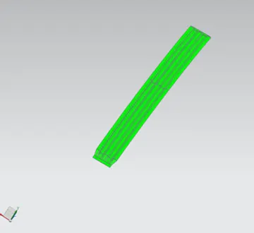
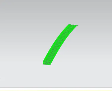
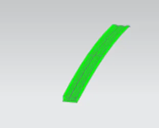
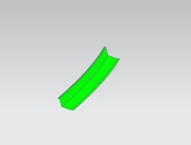
Draft analysis-
FR
1st
Centre
2nd
Rear
Roof Outer
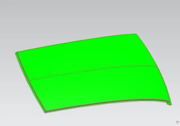
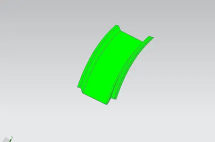
We gave a limit angle of 7 degree.
When the colour is green it means it has a positive draft it means area which are more than 7 degree is shown as green. If it is shwn in yellow that means it has less then 7 degrees and if in blue or red then it means it has negative draft.
CONCLUSION
We were successfully able to design the roof with all the roof rails for better support and strength. We designed it so as to satisfy the norms and regulations by calculating the heat distortion criteria and the snow load critera. While doing this we also understood about the methodology behind designing the roof of the car and what all we take into consideration while designing so.