Roof challenge
ROOF DESIGN CHALLENGE
Aim:
1. For the Given Roof styling, create an assembly by developing the essential flanges for the outer roof and creating the reinforcements.
2. Do a curvature study on the roof and perform calculations to determine the position of the Bow-roofs.
Automotive Roof
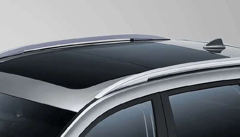
An automobile roof or car top is the portion of an automobile that sits above the passenger compartment, protecting the vehicle occupants from sun, wind, rain, and other external elements. Because the earliest automobiles were designed in an era of horse-drawn carriages, early automobile roofs used similar materials and designs.
Types of Automotive Roofs
1. Hardtops
When we talk about hardtops, we are referring to the common rigid forms of automobile roofs which we see around. In modern-day cars, this type of roof is made from metal or plastic. The fixed hardtop is your traditional car roof and is suitable for all climates and weather. It protects car occupants from the sun and wind when driving. It also offers more sense of privacy and noise-free driving. Many cars designed this way also tend to be more stable and solid than other types of roofs.
2. Sunroofs
This type of roof is also quite popular. A sunroof is an operable type of roof that allows for an opening in the roof of an automobile; say a window in a roof. It can allow either light or air or both to enter the vehicle. They are either operated manually or automatically.
3. Convertibles
Convertibles are passenger cars that can be driven with or without the entire roof in place. They were first introduced as open-air vehicles; no roofs, no sides. But by the end of the 19th century and the early 20th century, car engineers built more powerful engines that could power a folding roof. These were the forerunners of the convertibles that we have today. Convertibles allow an open-air driving experience. But apart from all of that, there are many drawbacks. One of them is noise. You would be exposed to the wind and you might not be able to hear anything else. Others are dust and dirt.
Roof Bow
A Roof Bow is a sheet metal part, usually spot welded to the BIW inner frame, forming the inner structure of the vehicle body. Its primary function is to supporting the roof panel loads, such as Oil Canning and local stiffness.
Automotive Roof Reinforcements Design
1. Roof
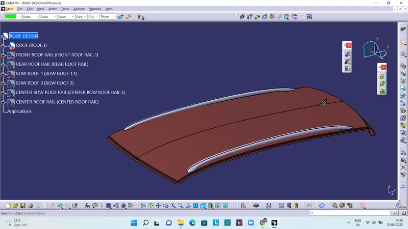
Draft Analysis of Roof
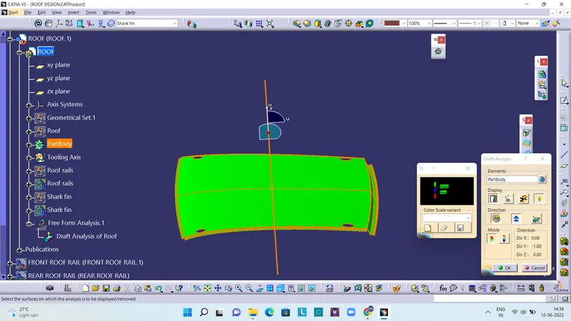
2. Front Roof Rail
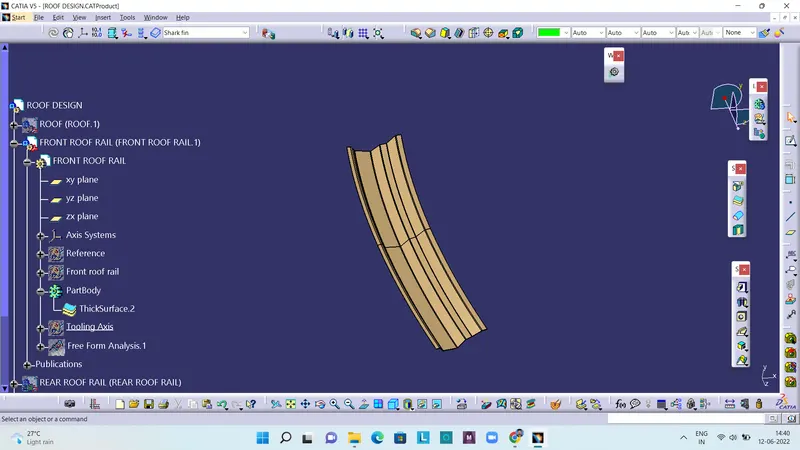
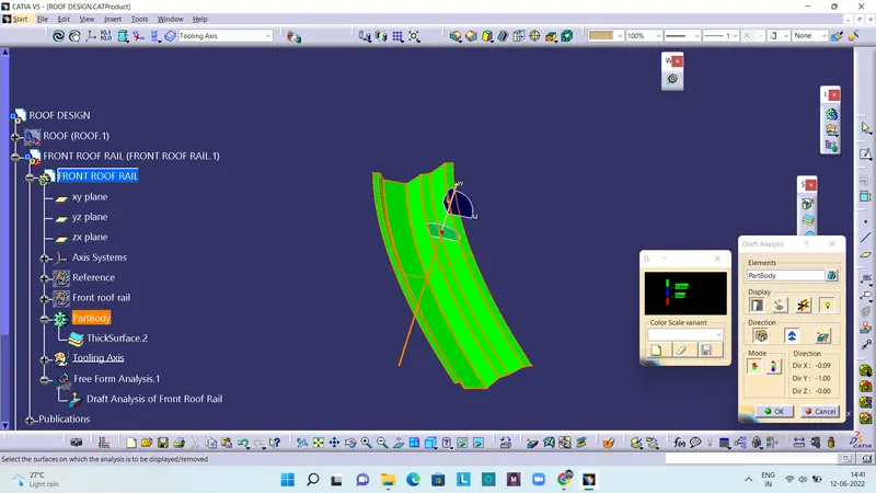
Draft Analysis of Front Roof Rail
Section Inertia Analysis of Front Roof Rail
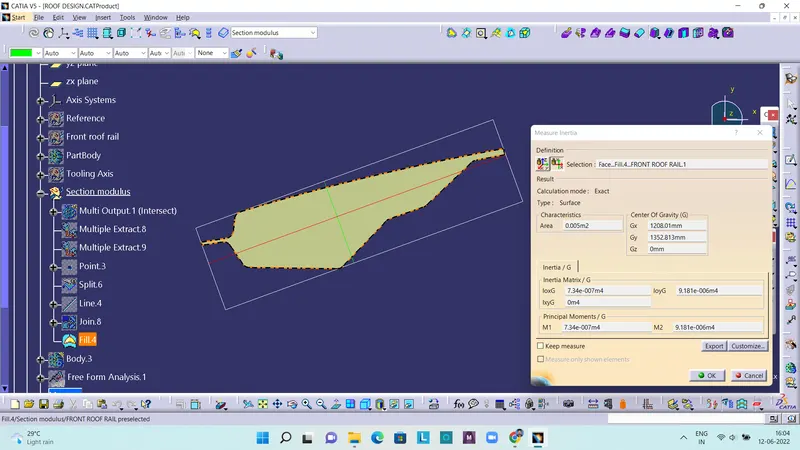
Minimum moment of inertia (I) = 7.34x10^(5) mm^(4)
Distance between the neutral axis and the extreme end of the object (y)= 189.713/2 = 94.8565 mm
Therefore, Section modulus (S)= I/y = (7.34x10^(5)) / 94.8565 = 7738.004 mm^(3)
3. Rear Roof Rail
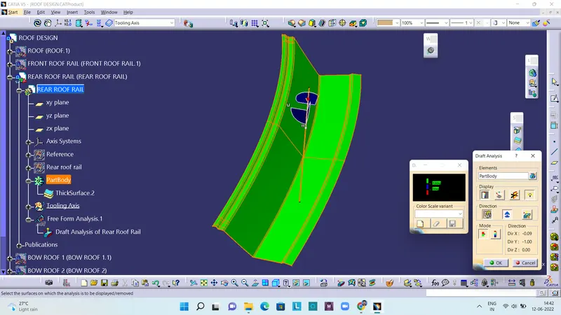
Draft Analysis of Rear Roof Rail
Section Inertia Analysis of Rear Roof Rail
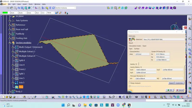
Minimum moment of inertia (I) = 7.067x10^(6) mm^(4)
Distance between the neutral axis and the extreme end of the object (y)= 223.309/2 = 111.6545 mm
Therefore, Section modulus (S)= I/y = (7.067x10^(6)) / 111.6545 = 63293.463 mm^(3)
4. Bow Roof 1
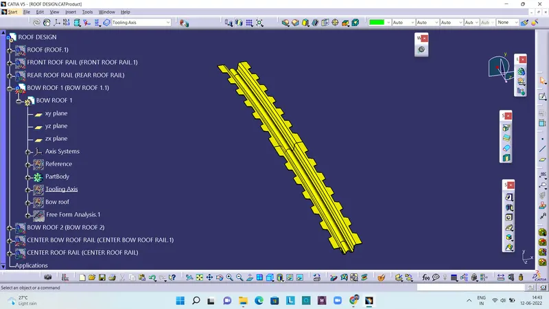
Draft Analysis of Bow Roof 1
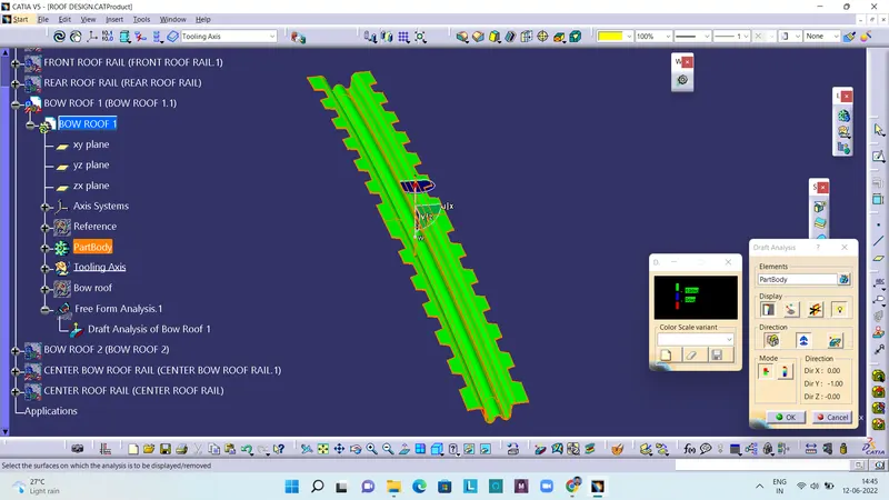
Section Inertia Analysis of Bow Roof 1
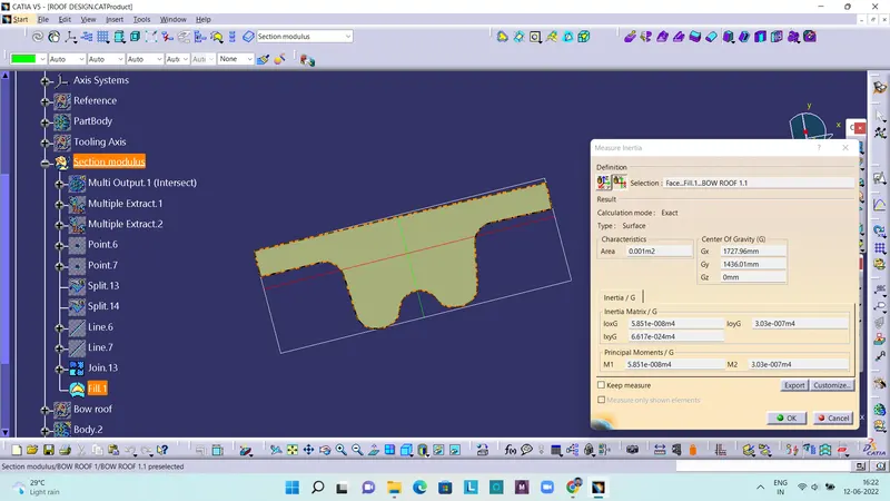
Minimum moment of inertia (I) = 5.851x10^(4) mm^(4)
Distance between the neutral axis and the extreme end of the object (y)= 74.893/2 = 37.4465 mm
Therefore, Section modulus (S)= I/y = (5.851x10^(4)) / 37.4465 = 1562.495 mm^(3)
5. Bow Roof 2
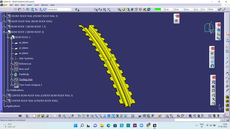
Draft Analysis of Bow Roof 2
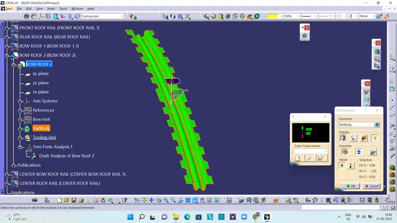
Section Inertia Analysis of Bow Roof 2
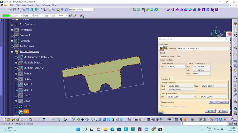
Minimum moment of inertia (I) = 5.878x10^(4) mm^(4)
Distance between the neutral axis and the extreme end of the object (y)= 74.909/2 = 37.4545 mm
Therefore, Section modulus (S)= I/y = (5.878x10^(4)) / 37.4545 = 1569.37 mm^(3)
6. Center Bow Roof Rail
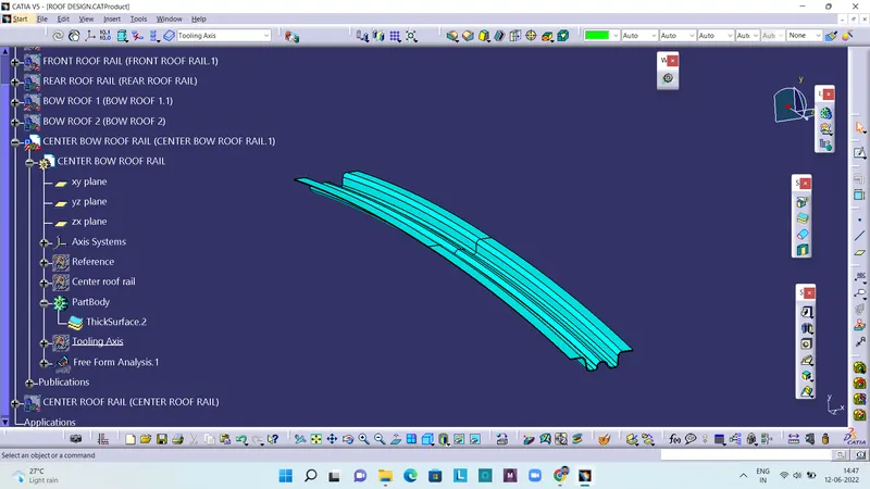
Draft Analysis of Center Bow Roof Rail
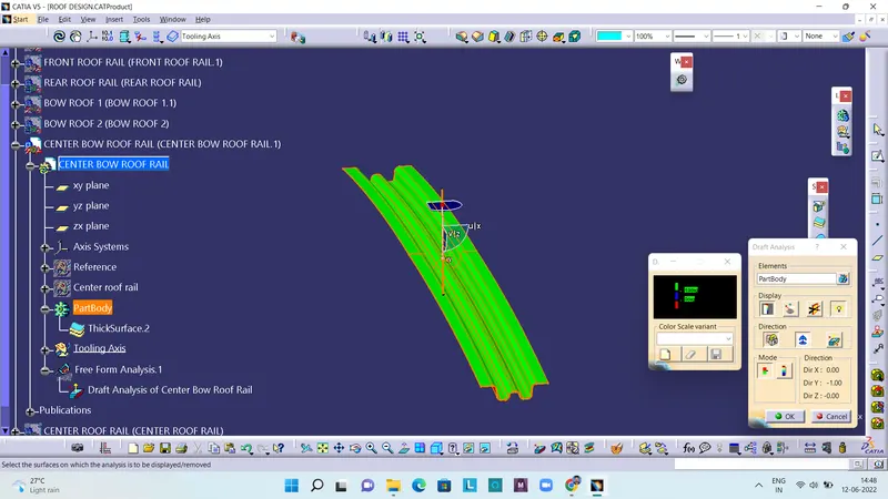
Section Inertia Analysis of Center Bow Roof Rail
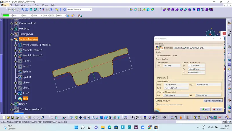
Minimum moment of inertia (I) = 7.803x10^(4) mm^(4)
Distance between the neutral axis and the extreme end of the object (y)= 90.01/2 = 45.005 mm
Therefore, Section modulus (S)= I/y = (7.803x10^(4)) / 45.005 = 1733.807 mm^(3)
7. Center Roof Rail
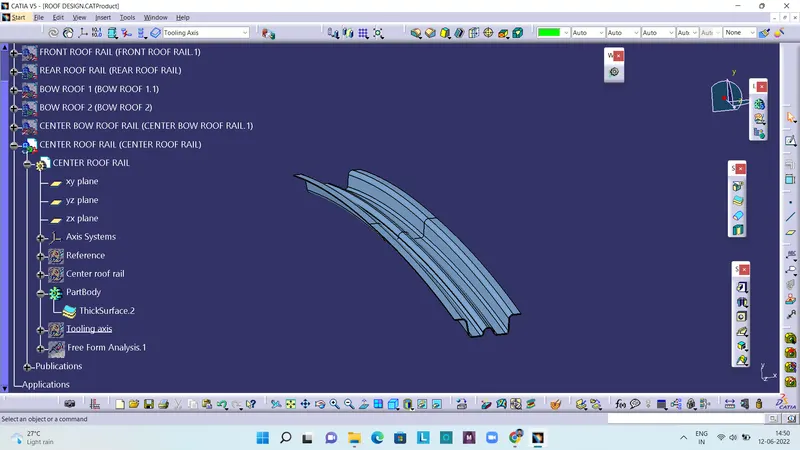
Draft Analysis of Center Roof Rail
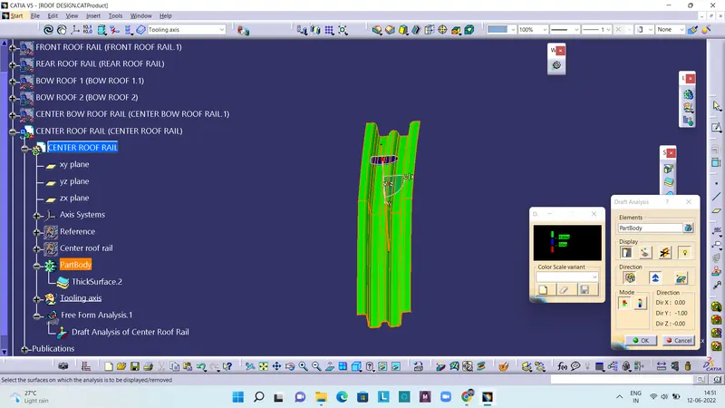
Section Inertia Analysis of Center Roof Rail
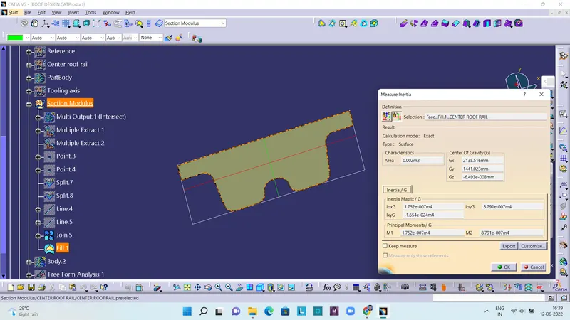
Minimum moment of inertia (I) = 1.752x10^(5) mm^(4)
Distance between the neutral axis and the extreme end of the object (y)= 89.997/2 = 44.9985 mm
Therefore, Section modulus (S)= I/y = (1.752x10^(5)) / 44.9985 = 3893.463 mm^(3)
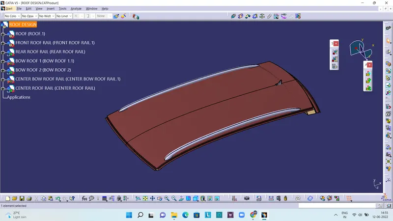
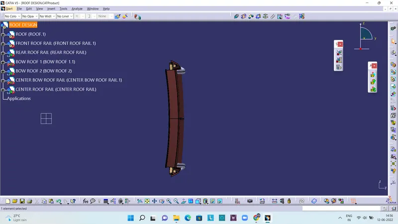
Automotive Roof Assembly
Isometric View:
Front View:
Side View:
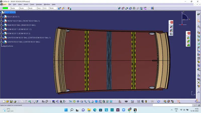
Top View:
Curvature Study
1. Heat Distortion Study
W = [1.73 x 10^(-3) x L] + [1.85 x 10^(-8) x (R^2)/t] + [ 1.10x10^(-3) x l] - 2.68
Where,
L = Roof Length in X-Direction[mm](Roof dimension in 0-Y)
R = Roof curvature
R = 2(Rx*Ry)/(Rx+Ry)
Rx = X curvature
Ry = Y curvature
t = Roof plate thickness [mm]
l = Bow Roof Span [mm]
Judgment Condition: W< 2.7
| Bows | Rx | Ry | R | l | L | t | (R^2)/t | W | OK/NG |
| FRR & BR1 | 5691.004 | 3040.548 | 3963.50 | 379.94 | 2035 | 0.75 | 20945776.33 | 1.645 | OK |
| BR1 & CRR | 4871.898 | 6329.724 | 5505.94 | 324.93 | 2035 | 0.75 | 40420500.38 | 1.945 | OK |
| CRR & BR2 | 4091.856 | 10559.888 | 5898.21 | 368.85 | 2035 | 0.75 | 46385174.94 | 2.10 | OK |
| BR2 & RRR | 3385.253 | 15700.792 | 5569.63 | 389.89 | 2035 | 0.75 | 41361037.78 | 2.03 | OK |
From the above study, we can see that the roof passes the Heat Distortion Criteria.
2. Snow Load Study
Qr = [Iy x t2] / [α x s x [(Rx + Ry)/2]2 x 10-8]
Where,
α = My x Lx2 x 10-12 , My = Y(Ly-Y)
t = Roof plate thickness [mm]
Ly = Distance between the front and rear roof Rails on the Vehicle along with 0Y[mm]
Length of Roof panel with the center point between Roof rail Front /Rear as the front and rear reference point.
Lx = Distance between the Left and Right end of the roof on the Roof BOW [mm]
The width of the roof panel is exposed on the surface.
Y = Distance from Front Roof Rail to Roof BOW[mm]
s = Distance for which Roof BOW bears divided load [mm]
s = L1/2 + L2/2
Iy = Geometrical moment of inertia of Roof BOW (Y cross-section )[mm4]
Rx = Lateral direction curvature radius of roof panel Y cross-section on Roof BOW [mm]
Roof panel curvature Radius of the Length Lx in Front view
Ry = Longitudinal Direction curvature radius of the Roof panel X cross-section on Roof BOW [mm]
Roof panel X curvature radius of length s in Side view
Judgment condition: Qr ≥ 3.1, 250 ≤ s ≤ 380
| Bows | Iy | α | Lx | Ly | Y | s | Rx | Ry | t | Qr | Determination |
| FRR & BR1 | 69540 | 0.8368 | 1154.76 | 1805.27 | 469.96 | 437.894 | 4265 | 3037.60 | 0.75 | 800.70 | OK |
| BR1 & CRR | 19800 | 0.6826 | 1096.364 | 1805.27 | 405.827 | 426.078 | 3788.664 | 6527.42 | 0.75 | 143.93 | OK |
| CRR & BR2 | 69830 | 0.6887 | 1065.589 | 1805.27 | 446.329 | 464.741 | 4216.47 | 10384.06 | 0.75 | 230.27 | OK |
| BR2 & RRR | 0.6998 | 1046.665 | 1805.27 | 483.153 | 4153.088 | 15449.845 | 0.75 | OK |
From the above study, we can see that the roof passes the Snow Load Criteria.