Roof challenge
Objective:
- To create reinforcements and flanges for the given Roof styling component according to given master sections.
- Perform roof curvature analysis and check for the correct position of bow roofs .
Introduction:
Roof of an automobile is the assembly which is at the top of passenger cabin . The primary objective of roof is to protect the passengers from external factors like rain ,sun,snow and protect the passengers in case of a roll over .
Roofs are provided with reinforcements in the front, center and rear by rails . Additional supports called bow roofs are also provided to ensure strength in case of rollovers .
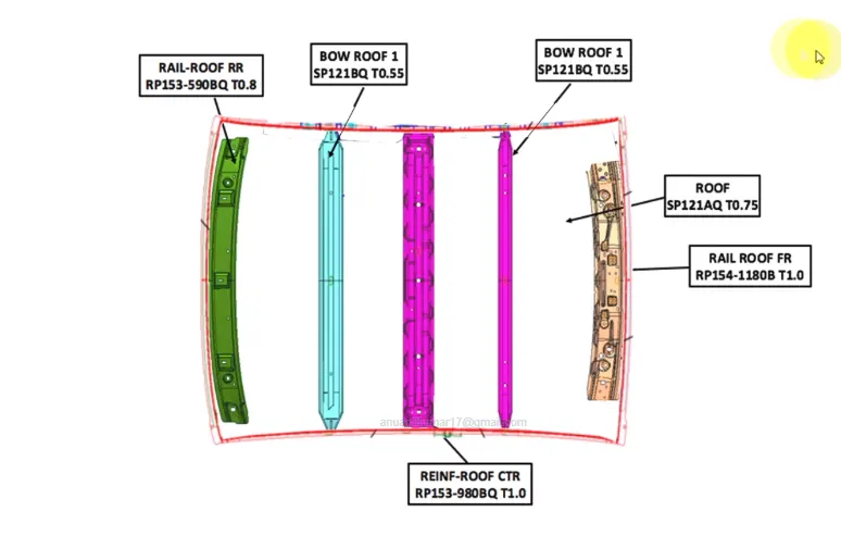
The position and dimension ofroof rails and bow roofs are of utmost importance because it has to clear certain parameters inorder to ensure safety and longer life . There are 2 main criterias used to calculate this
- a) Heat Distortion Criteria
Used to ensure that the vehicle roof withstands thermal expansion in various geographical conditions
- b) Snow Load Criteria
Used to ensure that the vehicle roof withstands loads caused by snowfall in cold regions .
Procedure For creation of ditch area
Step 1: Import the Roof surface file in a product file ,as a new part . Extract on half from top surface of styling component.
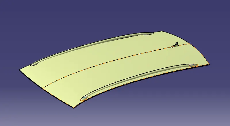
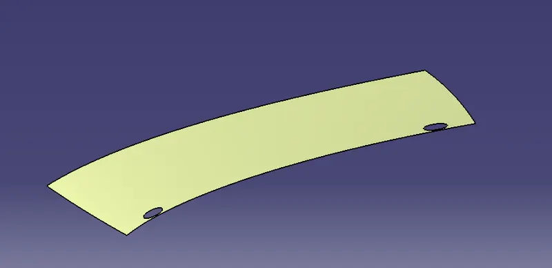
Step 2: extract edges on front left and rear part of roof and cut them near corners using split by plane option .
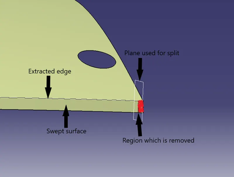
Step3: Create ditch area by using sweep commands and respective draft angle .
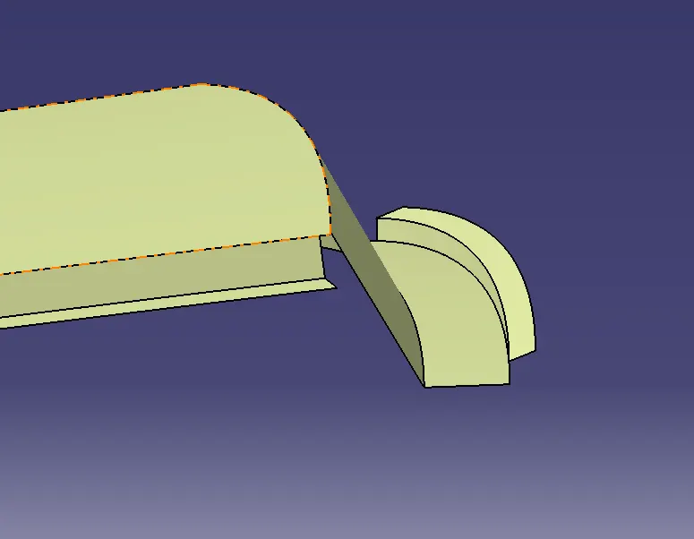
Step 4: Join all surfaces using join command . Apply fillets to all sharp edges .
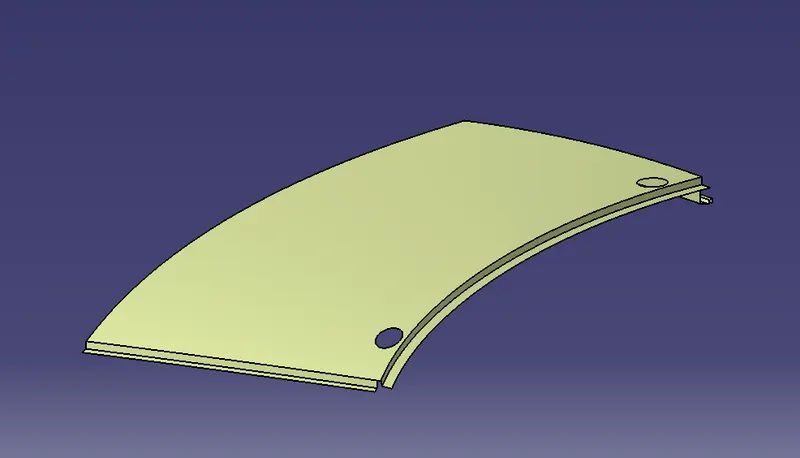
Step 5:Use symmetry option by sleting the correct plane to create the other half of the roof and join them together. use Fillets on all sharp edges.
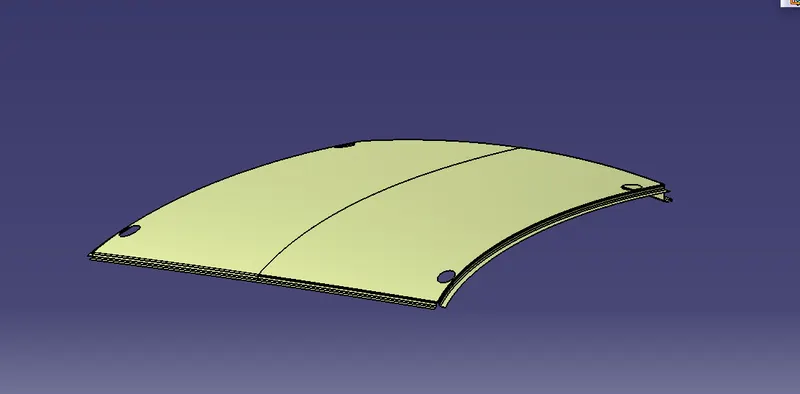
Now we have obtained Roof outer panel component .
Procedure to create front rail:
Given master section
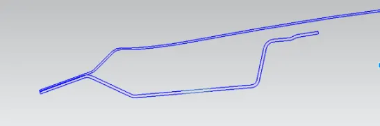
Step 1: Offset the front most surface from the roof outer component . Offset it to a value considering clearance for thickness of both component , direction of thickening .
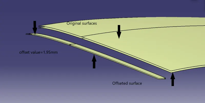
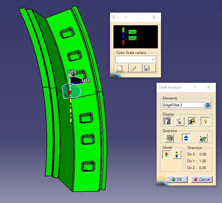
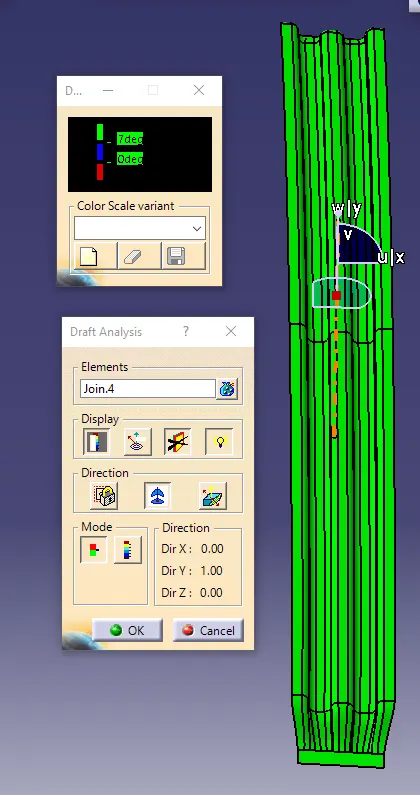
Step 2: Use sweep command and created surfaces applying minimum draft angle of 7 degree in tooling direction to obtain shape of master section.
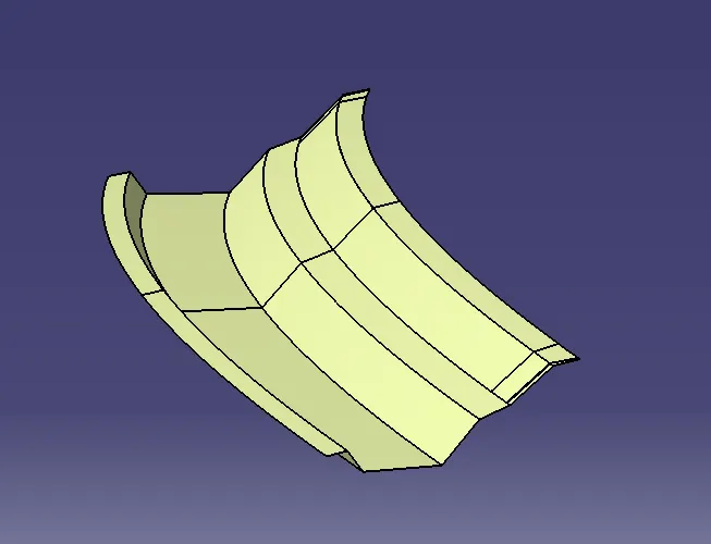
Step3: Apply fillets at all required regions and check master section of this with given master section
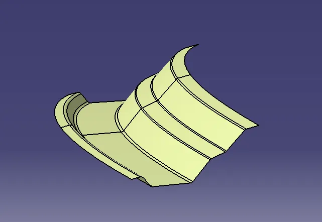
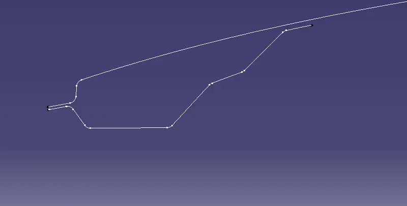
Hence we have created the front roof rail component. Applied thickness and performed draft analysis .
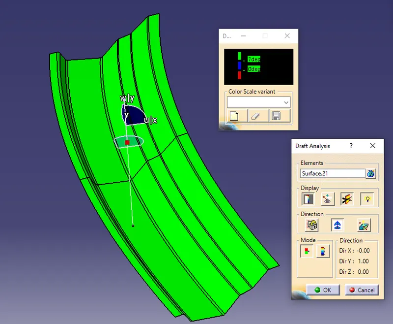
Procedure to create rear roof rail component:
Given master section
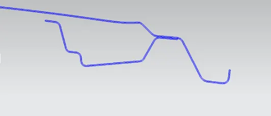
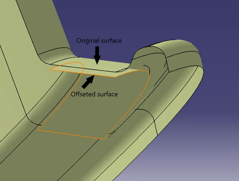
Step 1: Offset one half of the surface from roof outer section parallel to master section of rear roof panel
Step 2: Use sweep command to create surfaces applying required draft angle .
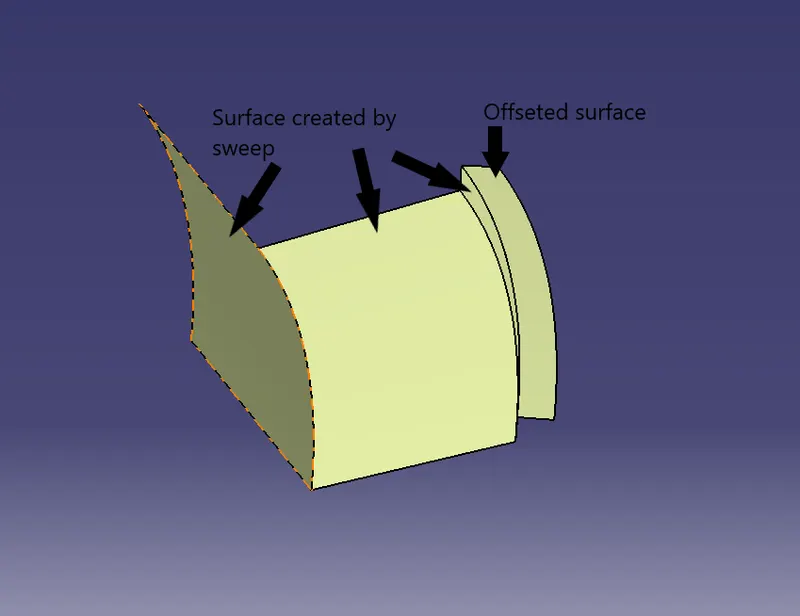
Step 3: Offset the roof outer panel to value taking thickness and clearance into consideration . Use parallel curve option to create 2 curves parallel ro rear edge of styling component. Split the offseted surfaces using these parallel curves . Extrapolate this surface towards the rear and create a surface using sweep applying required draft value . Use multisection surface to create a surface between Swept surfaces .
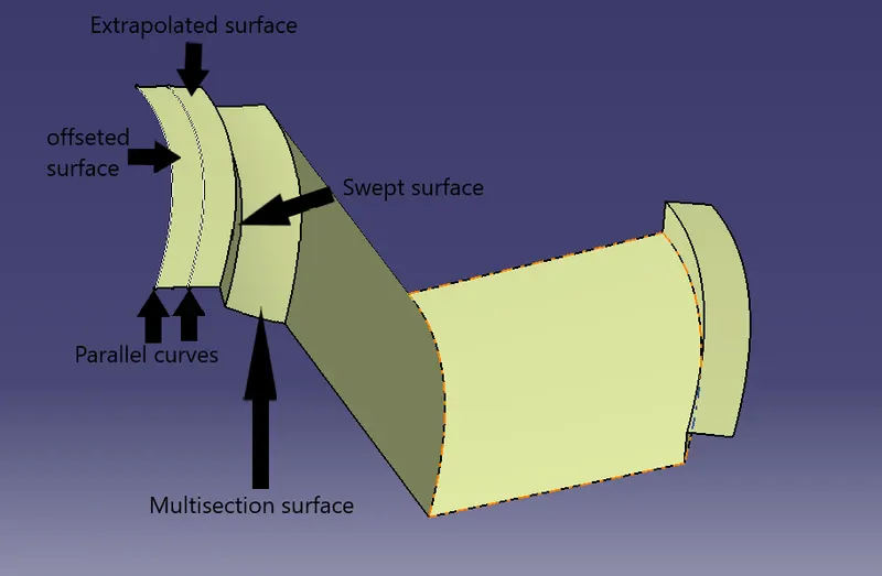
Step 4: Extrapolate the edge at the centre along -z direction and use split by plane (xy) option . Use symmetry to create other half of the rear roof rail . Use join to connect these 2 halves . Apply fillets at sharp edges .
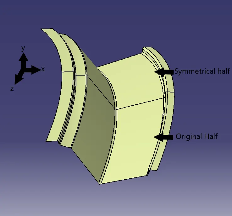
Step 5 : Embosses were created at required locations and draft analysis was performed
Master section of rear roof rail created
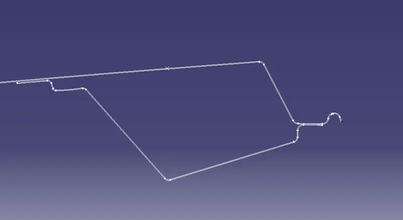
Hence the rear roof rail was created .
Procedure to create reinforcement center:
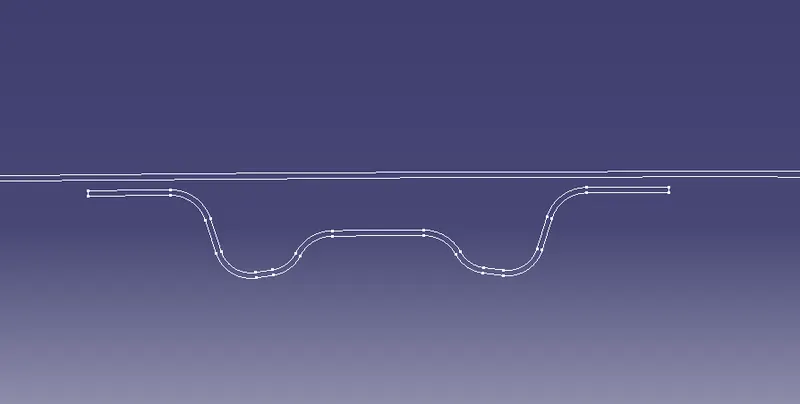
Given master section for roof reinforcement center
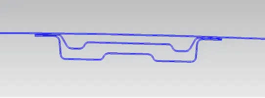
Step 1: Create a point on the extraced surface of Roof outer panel . Create a line along Z direction and project it onto the surface of roof outer panel . Use parallel curve with both sides option and create 3 parallel curves(total 6) in required length from this projected line with distance obtained from master section .
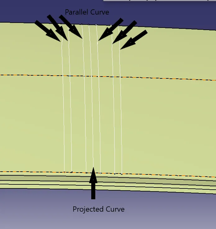
Step2: Split the surface according to these curves and offset to required value .
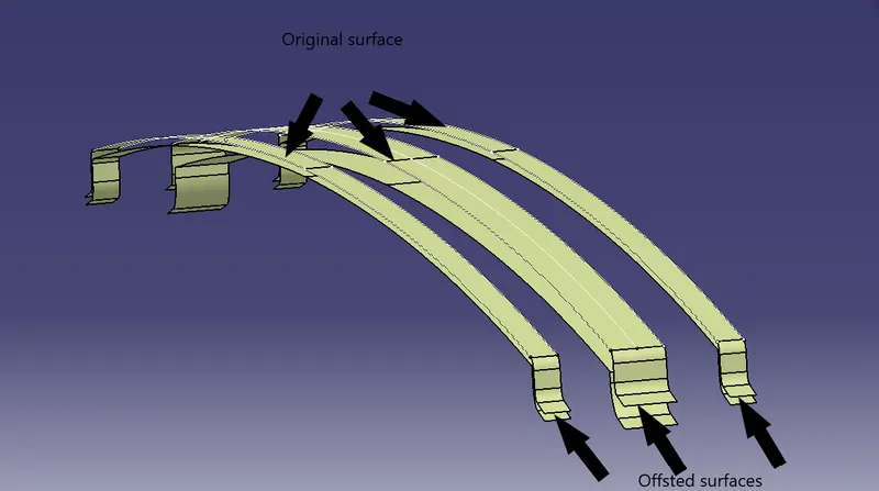
Step3: Use sweep applying required draft and and Multi section surface to create required surface .
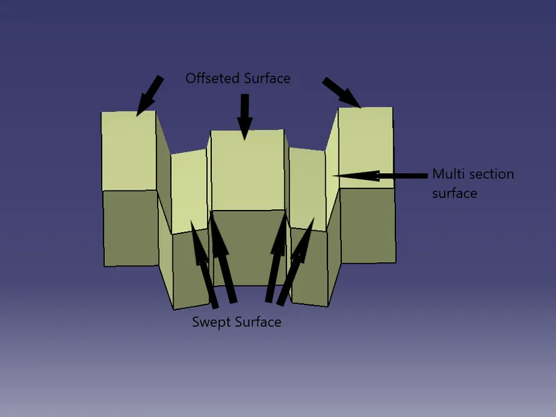
Step 4: Apply fillets at the required locations . Split and Offset the outermost surface to required value . Use connect curves to join these 2 surfaces at the edges
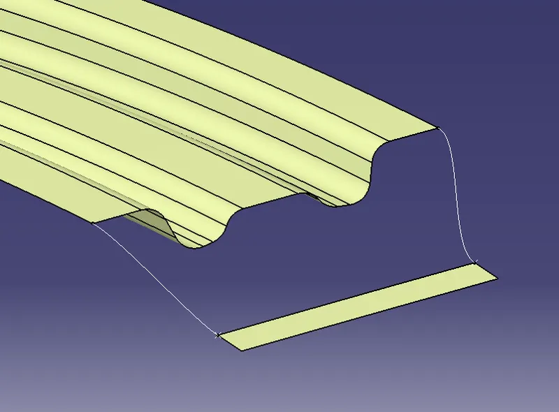
Step 5: Use multisection surface to create surfaces between these 2 surfaces .
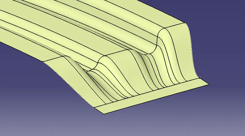
Step 6: Use join to connect these 3 surfaces . Use symmetry option to create the other half of the reinforcement center . Use join to connect these 2 halves .
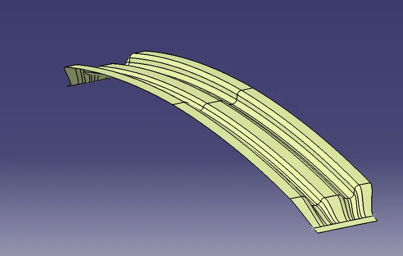
Step 7: Draft analysis was performed on this part . Thickness was applied to this to create required solid .
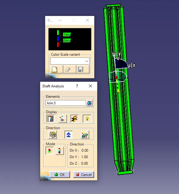
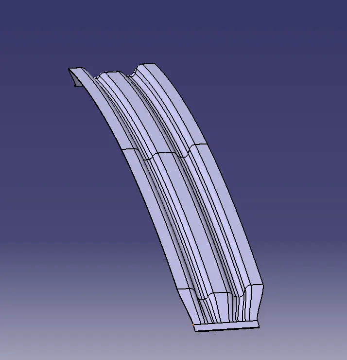
Master section of roof reinforcement center
Hence centre component was created .
Bow roof front and Bow roof rear were created using same procedure as that of reinforcement centre .
Draft analysis and master section of Bow roof front .
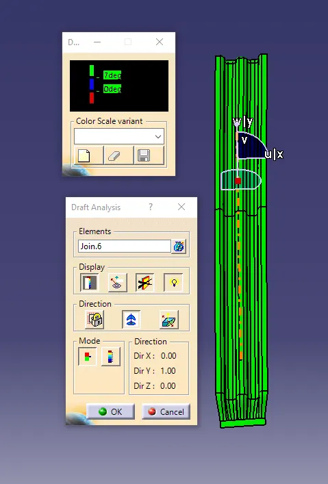
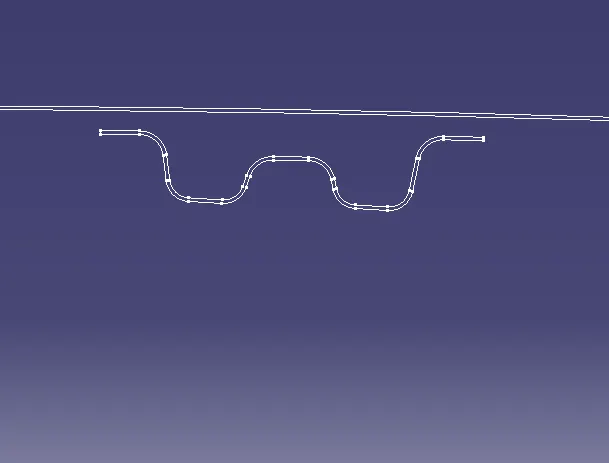
Draft analysis and master section of bow roof rear
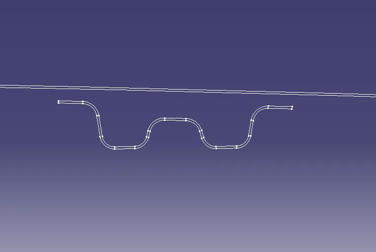
Hence we have created Bow roof front and rear .
Roof Curvature Study:
- Bow roof prediction for heat distortion
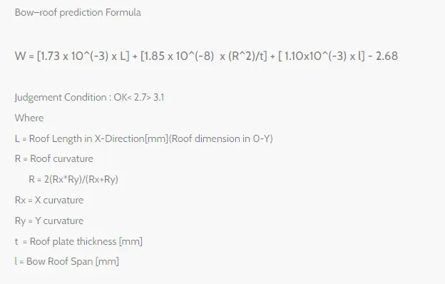
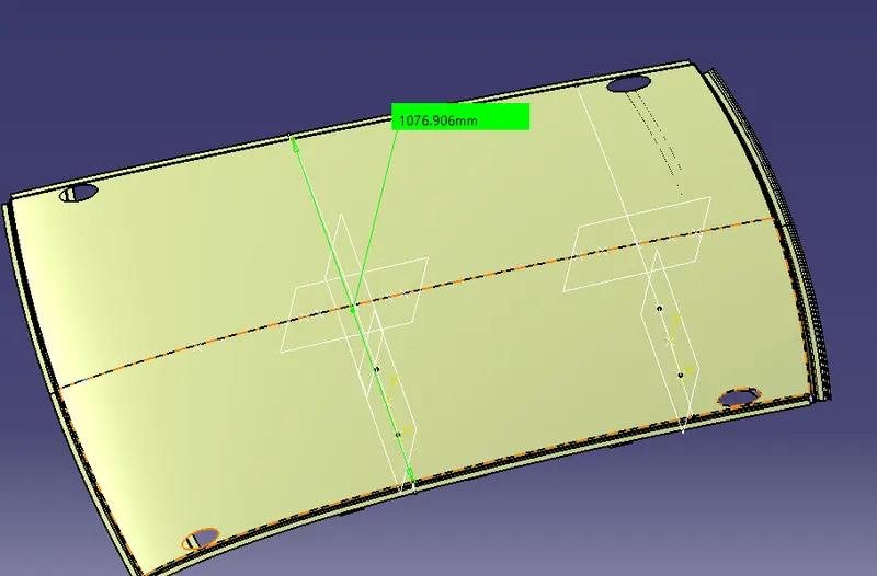
Measurement of L
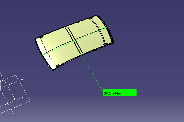
Measurement of l2
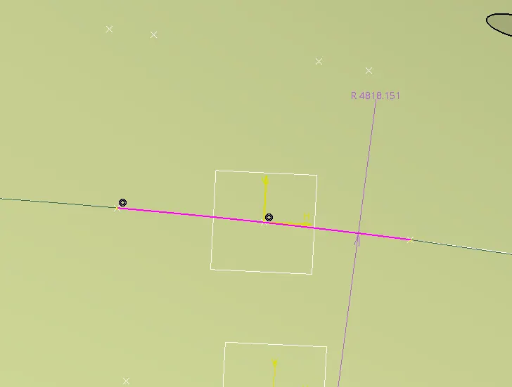
Measurement of Rx2
Measurement of Ry2
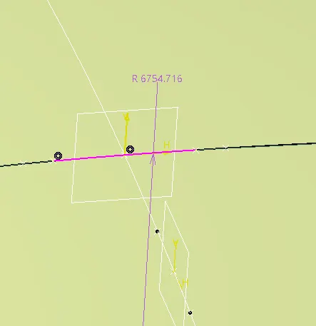
Table for all the values and calculations

All the values for W meets the condition as either <2.7 or < 3.81 . Hence the position of bow roofs are acceptable .
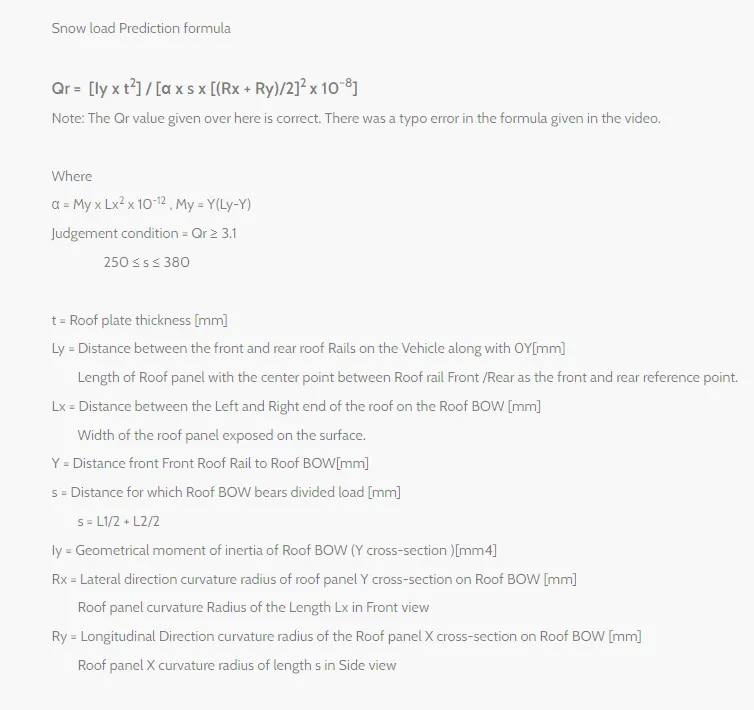
- Snow load prediction formula
Measurement of Lx1
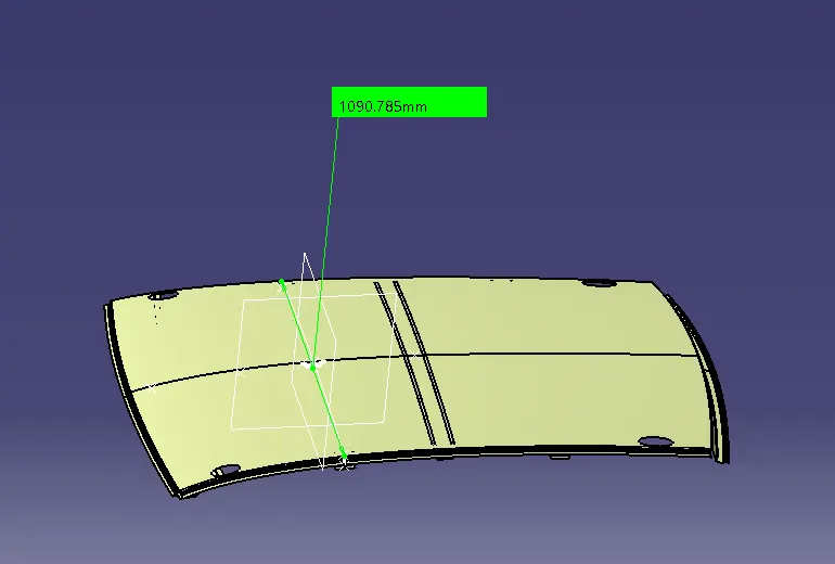
Measurement of Ly
Measurement of Rx2
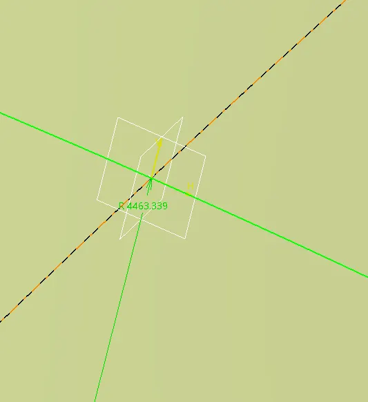
Measurement of Ry2
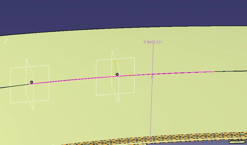
Measurement of Iy1
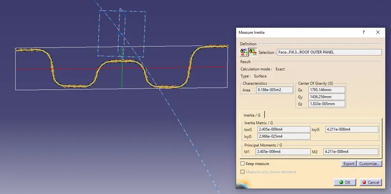
Measurement of L1=y1
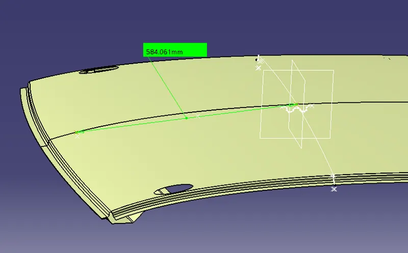
Table for calculations

Here Qr>=3.1 Hence we can deduct that the position of Bow roofs are correct .
Section Modulus Study
Table for section modulus of various components

From the table we can understand that rear roof rail is the most stiff component . This is because of the fact that the rear door is attached to rear roof rail and the component must have enough stiffness to support its weight . Front and rear roof rails are the primary stiffening components of the roof . Additional support is provided by reinforcement center and bow roofs .
Inference
1) The support flanges and reinforcements were created according to master sections .
2) Position of bow roofs were verified using prediction formulas .
3) Section Inertia study was conducted on all components created .