Roof challenge
ROOF DESIGN USING NX CAD
1 INTRODUCTION
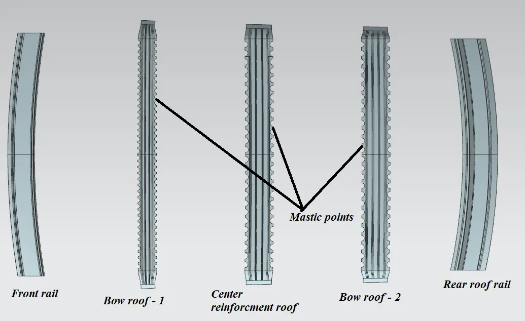
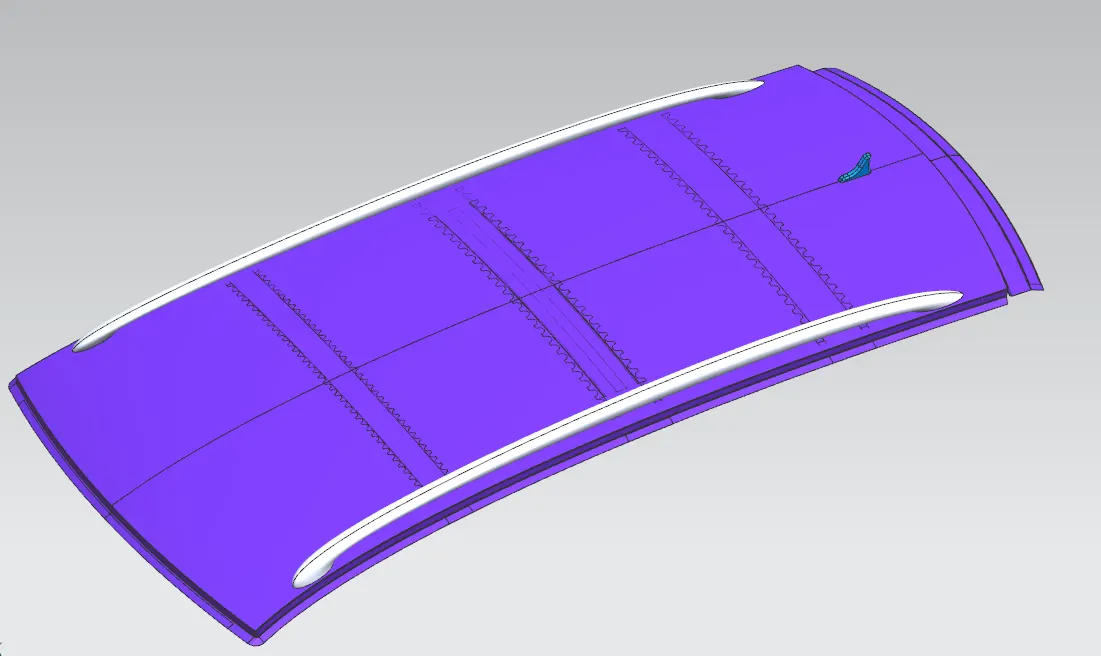
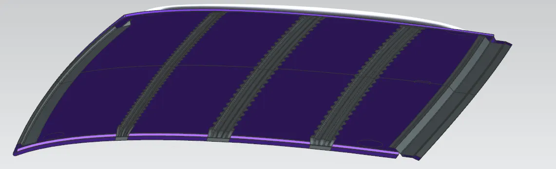
The roof is the top layer of the car, which protects the passengers from the sunlight, rain, and wind. The roof consists of a front roof rail, bow roof, center roof reinforcement, and rear roof rail. The bow roof is used in the flat section of the roof to give the support.
In the present challenge, a roof is modeled in NX CAD. Heat distortion criteria, snow load criteria, draft analysis, and section modulus calculation for different parts and the entire roof is being calculated.
2 PROCEDURE TO MODEL ROOF IN NX CAD
- The parent roof section is obtained from the styling department.
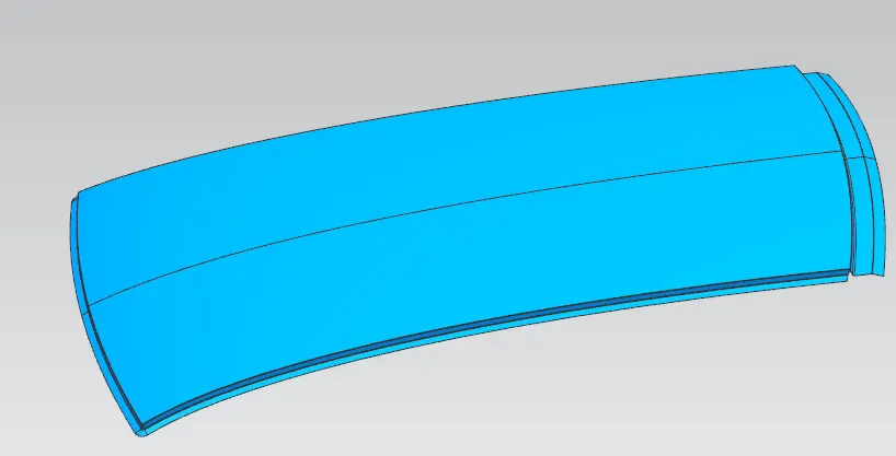
- A copy of the roof is taken to the midsection using OFFSET SURFACE with 0 mm distance and TRIM SHEET using the midplane.
- From the master section of the front roof rail, the front roof is designed precisely to use LAW EXTENSION, OFFSET SURFACE, and TRIM SHEET command. The front flange must be greater than 15 mm to accommodate the spot welding of the sheets.
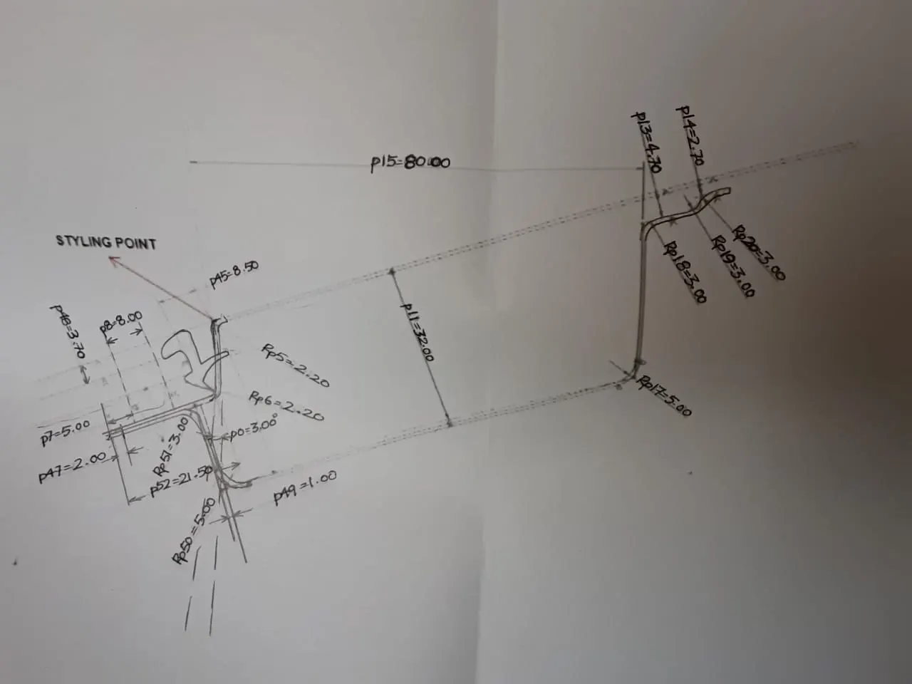
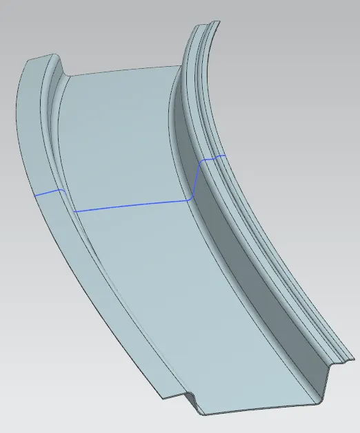
- The bow roof - 1, center roof, and bow roof – 2 is designed as per the master sections using the OFFSET SURFACES, TRIM SHEET, STUDIO SURFACE, BRIDGE CURVES command.
- A gap of 0.5 mm is given between the outer roof and bow roofs for the mastic points.
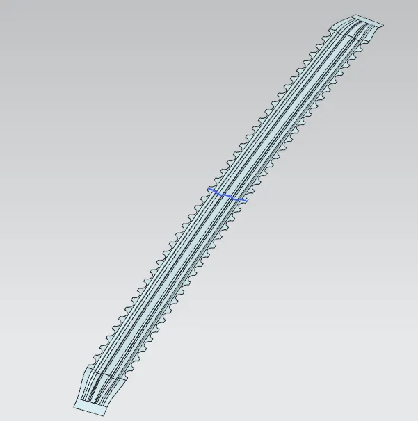
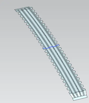
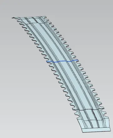
- A rear roof is modeled the same as the master section given.
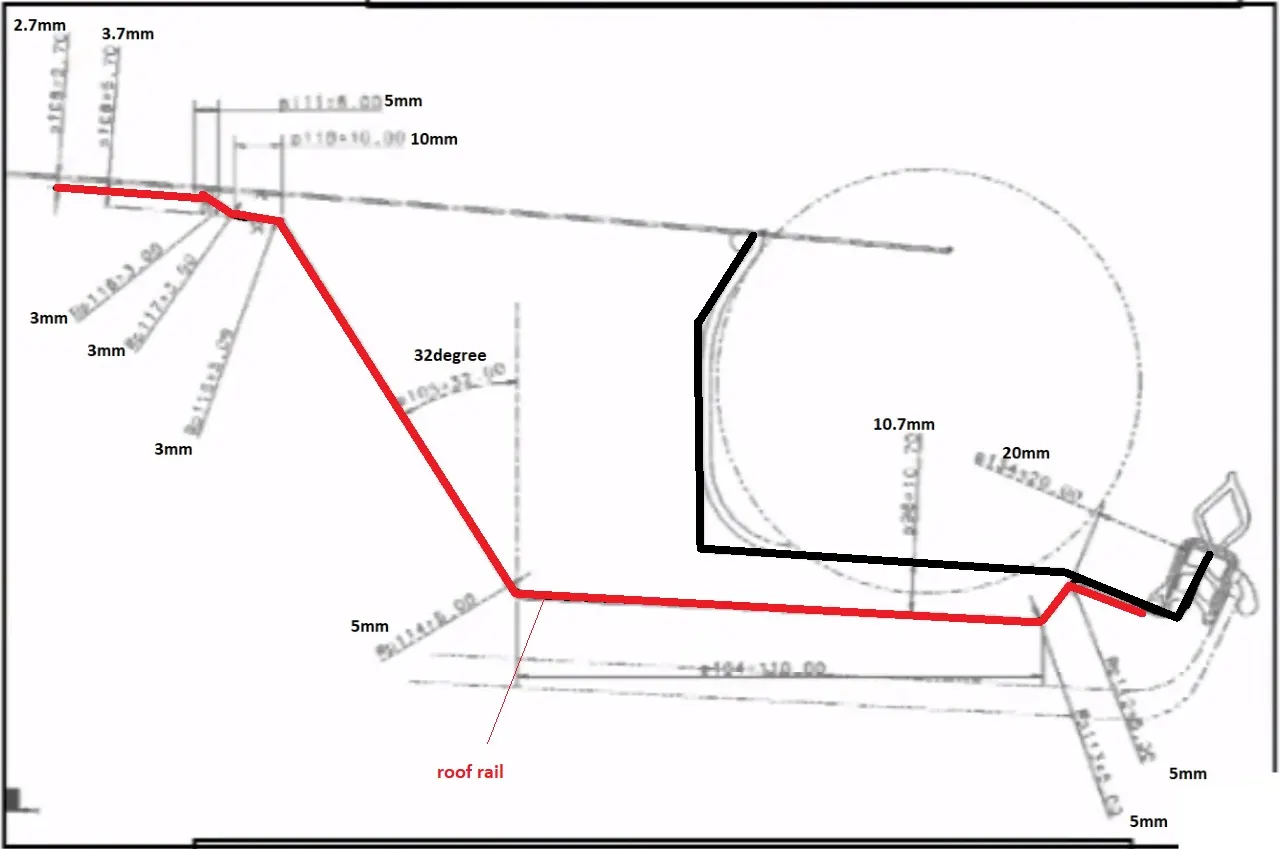
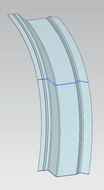
- For all the surfaces, a minimum angle of 7º is maintained for the punching to occur.
- FACE BLEND is used to smooth the faces.
3 DRAFT ANALYSIS
Using the DRAFT ANALYSIS command, the draft analysis is done for all the components. It is observed that the components are in acceptable green color.
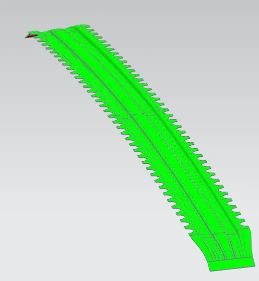 Figure: Bow roof 1
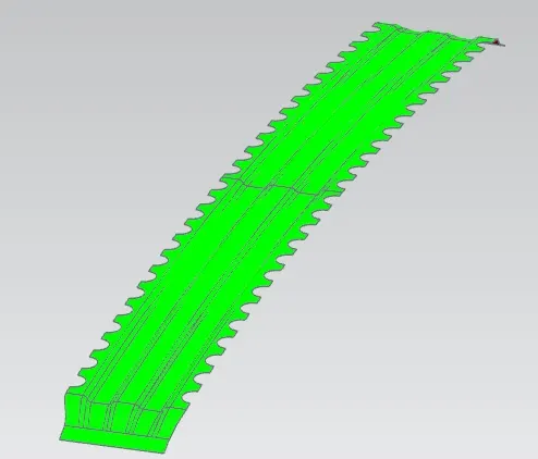 Figure: Bow roof 2
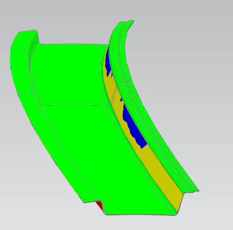 Figure: Front roof rail
The yellow and blue region in the front roof rail suggests that the angle is less than `5^o`. The master section has a `3^o` angle there so it can be considered there.
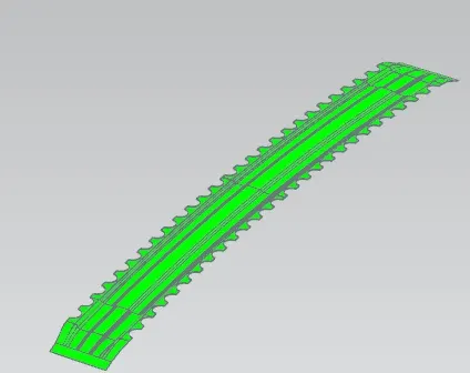 Figure: Center roof reinforcement
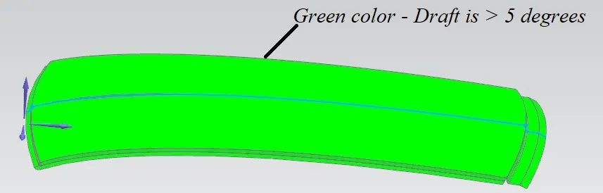 Figure: Outer roof
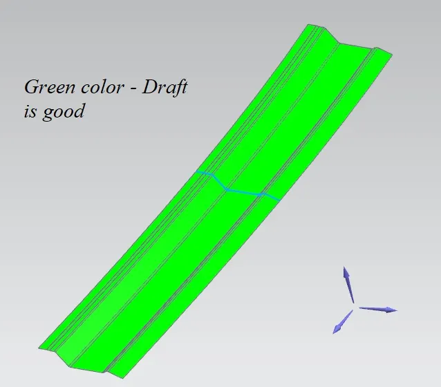 Figure: rear roof rail
4 SECTION MODULUS
Section modulus calculation is done for all the individual parts and the whole roof part.
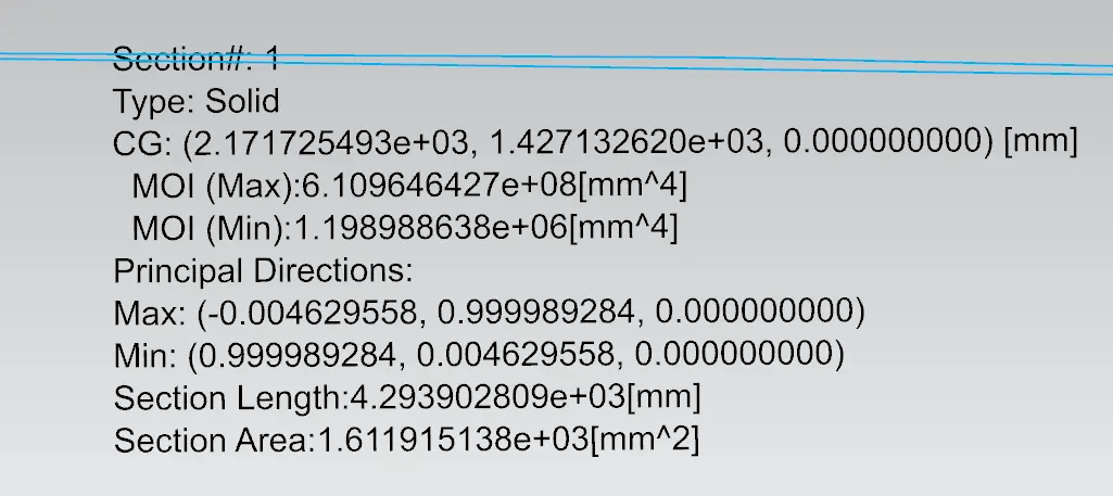 Figure: Outer roof
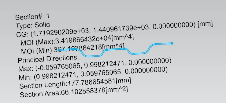 Figure: Bow roof 1
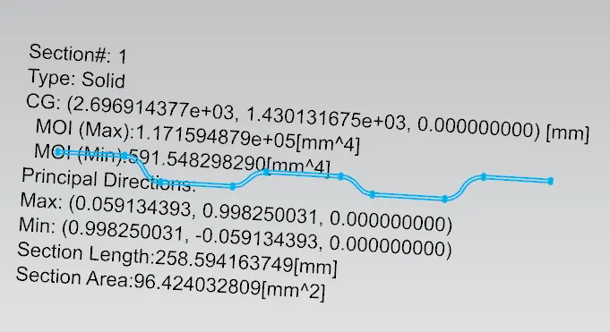 Figure: Bow roof 2
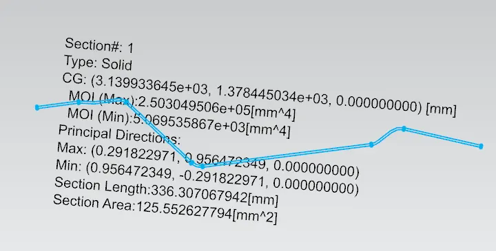 Figure: Rear roof rail
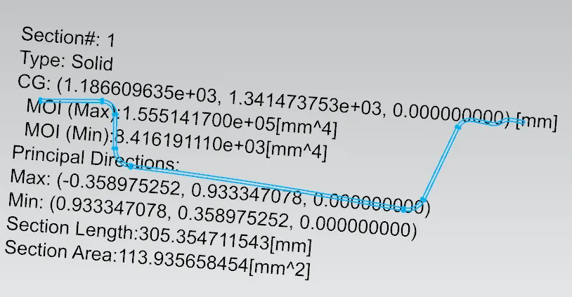 Figure: Front roof
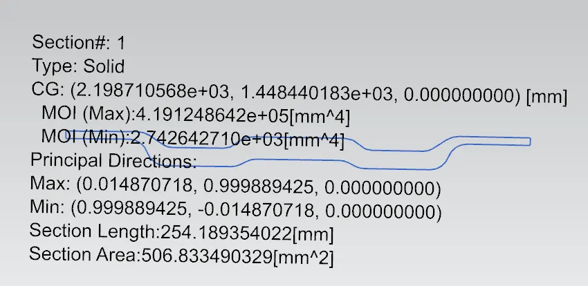 Figure: Mid roof reinforcement
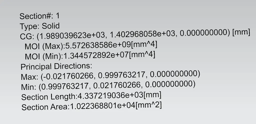 Figure: Entire roof
Table: Section modulus calculation
|
S. No |
Section |
Imax (mm4) |
Imin (mm4) |
y (mm) |
Smax = `I_max/y`(mm3) |
Smin = `I_min/y`(mm3) |
|
1. |
Front roof rail |
1.5551E5 |
8.4161E3 |
114.2 |
1361.73 |
73.694 |
|
2. |
Bow – 1 |
3.41986E4 |
367.197 |
80 |
427.4825 |
0.8399 |
|
3. |
Center roof |
4.19124E5 |
2.74264E3 |
120 |
3492.7 |
22.855 |
|
4. |
Bow – 2 |
1.17159E5 |
591.54 |
120 |
976.325 |
4.9295 |
|
5. |
Rear roof |
2.50304E5 |
5.0695E3 |
149.2 |
1677.64 |
33.977 |
|
6. |
Outer roof |
6.10964E8 |
1.19898E6 |
1989.6 |
307078.80 |
602.623 |
|
7. |
Entire roof |
5.5726E9 |
1.34457E7 |
1989.6 |
2800864.49 |
6757.991 |
5 HEAT DISTORTION CRITERIA
The heat distortion criteria give the bow placement position on the roof. The formula to calculate heat distortion criteria is
1. `R_y` Calculation:
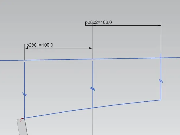 Figure: Front rail to Bow 1
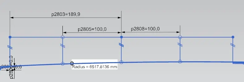 Figure: Bow 1 to Centre roof
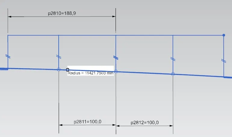 Figure: Center roof to Bow 2
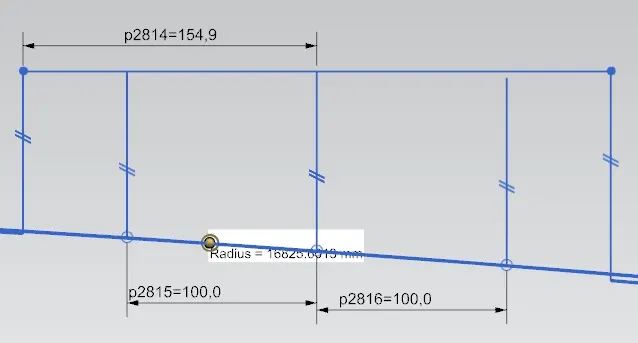 Figure: Bow 2 to Rear roof
2. `R_x` Calculation:
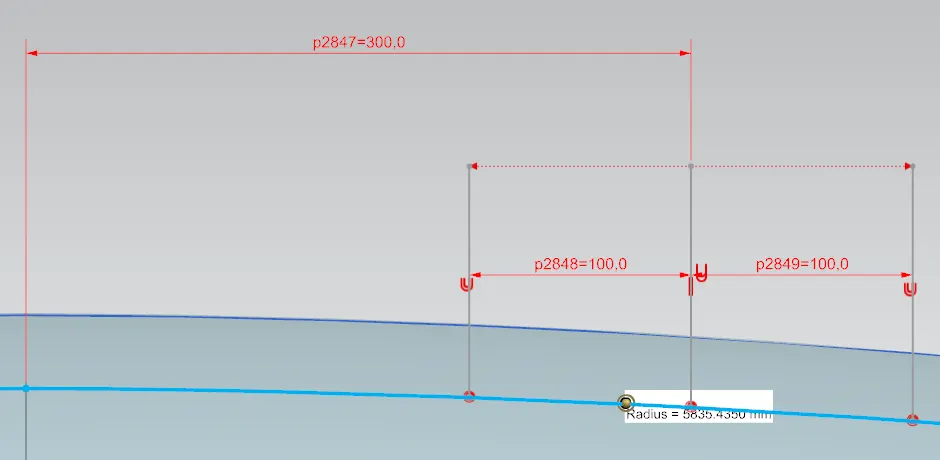 Figure: Front rail to Bow 1
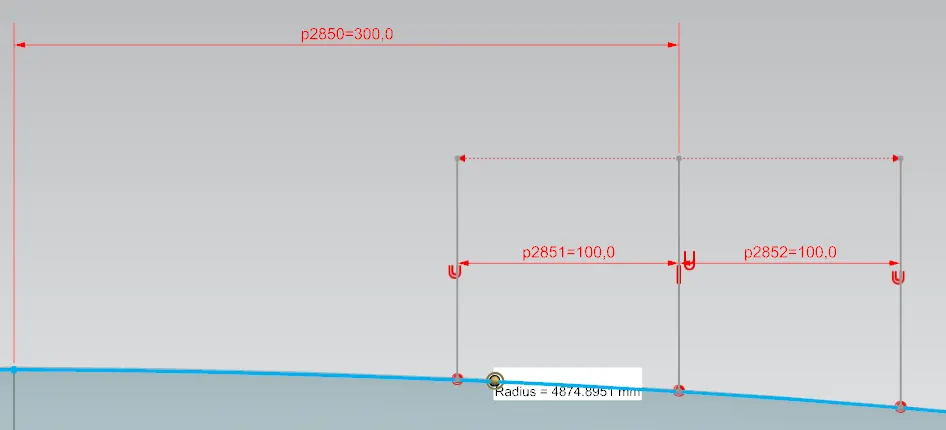 Figure: Bow 1 to Centre roof
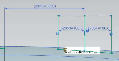 Figure: Center roof to Bow 2
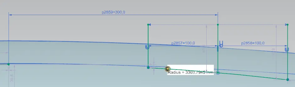 Figure: Bow 2 to Rear roof
2. `L_y` :

3. Formula
`W=(1.73*10^-3*L)+(1.85*10^-8*R^2/t)+(1.10*10^-3*l)-2.68`
Judgment condition must be `ok<2.7>3.1(NG)`
Where L = Length of the roof in the x-direction (o-y)
R = Roof curvature = `=(2*(R_x*R_y))/(R_x+R_y)`
t = roof thickness (mm)
l = Bow roof span (mm)
Table: Heat distortion criteria calculation
| S.No | Section | L (mm) | Rx (mm) | Ry (mm) | R (mm) | t (mm) | l (mm) | W | Ok/NG |
| 1 | FR-Bow1 | 1990.22 | 5835.43 | 2778.98 | 3764.981 | 0.75 | 440.9 | 1.597723 | Ok |
| 2 | Bow1-CR | 1990.22 | 4874.89 | 6517.81 | 5577.889 | 0.75 | 379.8 | 1.948311 | Ok |
| 3 | CR-Bow2 | 1990.22 | 4004.93 | 11421.75 | 5930.415 | 0.75 | 377.9 | 2.046293 | Ok |
| 4 | Bow2-Rear | 1990.22 | 3303.79 | 16825.6 | 5523.093 | 0.75 | 309.7 | 1.856196 | Ok |
From Table 2, it is observed that the 'W' is in OK condition for all the sections, so the present roof model is acceptable.
6 SNOW LOAD CRITERIA
The snow load criteria are calculated using the following formula
`Q_r=(l_y*t^2)/(alpha*s*((R_x+R_y)/2)^2*10^-8`
Where `alpha=M_y*L_x^2*10^-2`
`M_y=y(L_y-y)`
Judgement condition = Qr ≥ 3.1
250 ≤ s ≤ 380
t = Roof plate thickness [mm]
Ly = Distance between the front and rear roof Rails on the Vehicle along with 0Y[mm]
Length of Roof panel with the center point between Roof rail Front /Rear as the reference point of the front and the rear.
Lx = Distance between the Left and Right end of the roof on the Roof BOW [mm]
Width of the roof panel exposed on the surface.
Y = Distance front Front Roof Rail to Roof BOW[mm]
s = Distance for which Roof BOW bears divided load [mm]
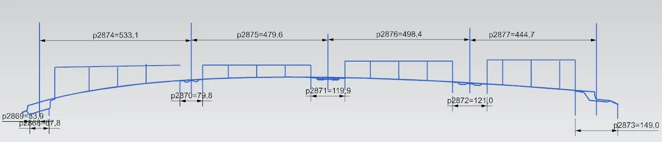
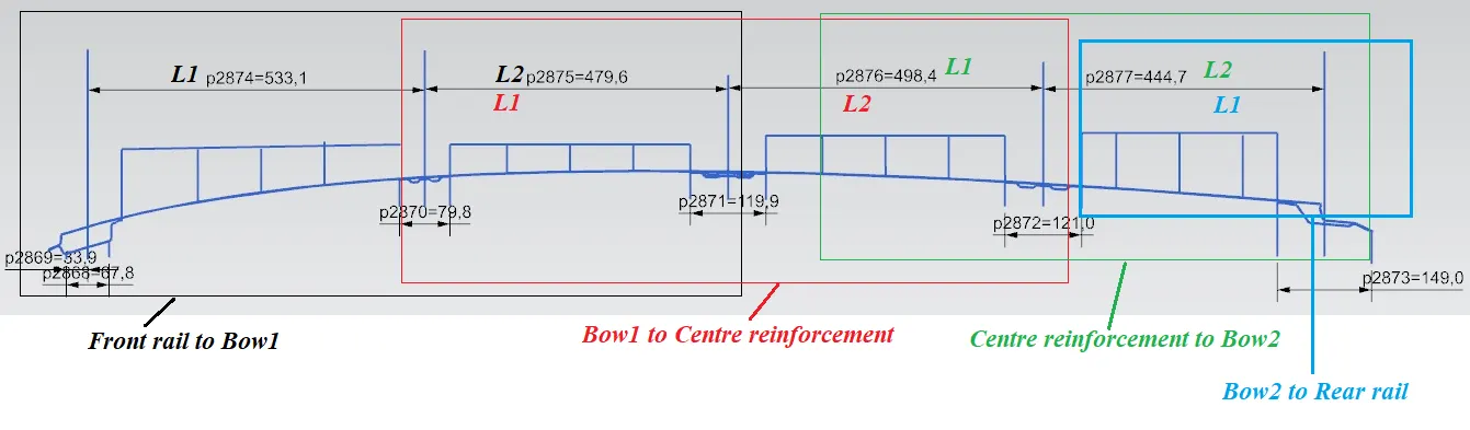
s = L1/2 + L2/2
Iy = Geometrical moment of inertia of Roof BOW (Y cross-section )[mm4]
Rx = Lateral direction curvature radius of roof panel Y cross-section on Roof BOW [mm]
Roof panel curvature Radius of the Length Lx in Front view
Ry = Longitudinal Direction curvature radius of the Roof panel X cross-section on Roof BOW [mm]
Roof panel X curvature radius of length s in Side view
1. Ry

2. Rx
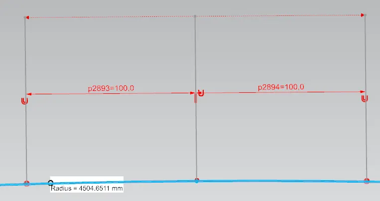 Figure: Front rail to Bow 1
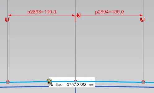 Figure: Bow 1 to Centre roof
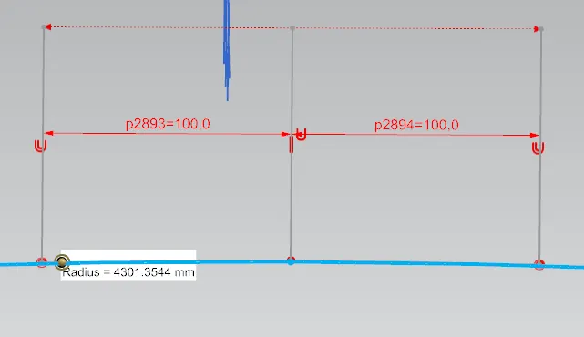 Figure: Center roof to Bow 2
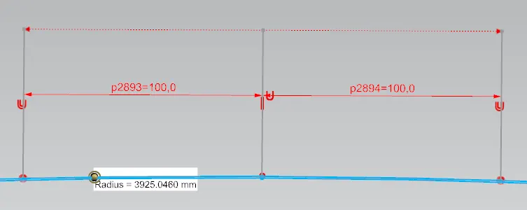 Figure: Bow 2 to Rear roof
3. S
4. Lx
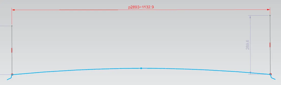 Figure: Front rail to Bow 1
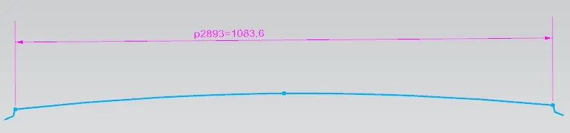 Figure: Bow 1 to Centre roof
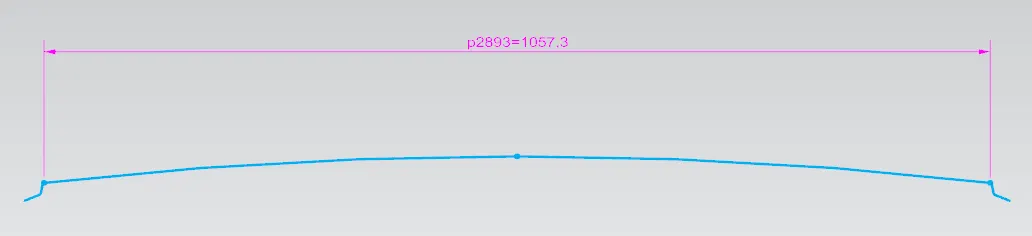 Figure: Center roof to Bow 2
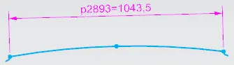 Figure: Bow 2 to Rear roof
5. Ly
From Table 3, the snow load criteria are calculated and it is observed that the results of Qr are in OK condition.
| S.No | Section | ly (mm^4) | t (mm) | Ly (mm) | y (mm) | Lx (mm) | My | alpha | L1 (mm) | L2 (mm) | s | Rx | Ry | Qr | Ok/NG |
| 1 | FR-Bow1 | 3.67E+02 | 0.75 | 1990.22 | 440.9 | 1132.87 | 683095.2 | 0.876681 | 533.1 | 479.6 | 506.35 | 4504.65 | 2592.34 | 3.695226 | Ok |
| 2 | Bow1-CR | 2.74E+04 | 0.75 | 1990.22 | 379.8 | 1083.57 | 611637.5 | 0.718138 | 479.6 | 498.4 | 489 | 3797.33 | 6475.41 | 166.5182 | Ok |
| 3 | CR-Bow2 | 5.92E+02 | 0.75 | 1990.22 | 377.9 | 1057.28 | 609295.7 | 0.681096 | 498.4 | 444.7 | 471.55 | 4301.35 | 11386 | 4.156285 | Ok |
| 4 | Bow2-Rear | 0.00E+00 | 0.75 | 1990.22 | 309.7 | 1043.5 | 520457 | 0.566722 | 444.7 | 0 | 222.35 | 3925.04 | 367805.6 | 0 |
7 CONCLUSION
The roof is designed in NX CAD. The use of commands is studied. The calculation of heat distortion criteria and snow load criteria is done. All the snow load and heat distortion criteria results for the current roof are in OK condition. So the present roof is acceptable.