Roof challenge
ROOF DESIGN:
INTRODUCTION:
Roof is the unit was available in above the passenger car.
It was there to protect from heat, snow, rain and from external elements.
To protect the passengers at the time roll over accidents.
It is the important unit available in the vehicle and act like as head of the passenger car.
Look will change depends of the vehicle like SUV, sedan, luxury, etc..
We can carry the load over the roof top to move from one place to other place.
OBJECTIVE:
To design a passenger car roof by using the inputs given by the smart stylish team with surface model.
Material and thickness will fix depends on the standard regulations.
Aesthetic look need to improve at the time of final stage.
DESIGN CONSIDERATION:
These criteria has to be follow to get perfect roof.
- Visibility criteria
- Head clearance
- Curvature study
- Heat distortion study
- Snow load study
- Process constraints.
PART DETAILS:
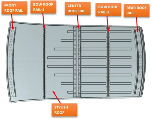
FRONT ROOF RAIL:
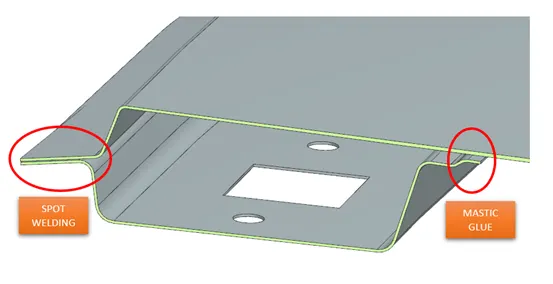
It is available in front side and while designing we need to consider the visibility criteria and front windshield gluing.
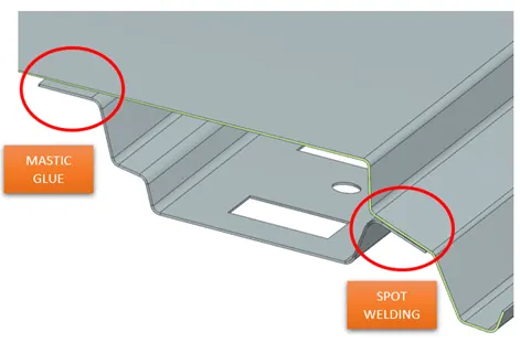
It will join with the roof by spot welding on one side and mastic glue on other side.
Mastic glue process is available to avoid welding impression on smart stylist roof top while welding.
BOW ROOF RAIL-1:
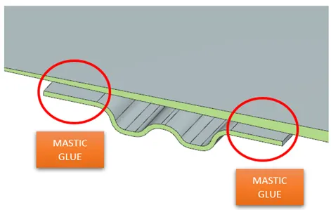
It is the unit available in between front roof railand centre roof rail.
It was acting like a stiffener and giving strength to the roof.
It will join with the roof by using mastic glue instead of spot welding to avoid the weld impression.
CENTER ROOF RAIL:
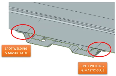
It is the unit available in center of the roof assy.
This very much important part available in the roof assy.
It consists of two roof rail for the purpose of extra safety.
Inner center roof rail need to spot welding with roof assy.
Outer centre roof rail need to do the mastic glue with inner center roof rail.
BOW ROOF RAIL-2:
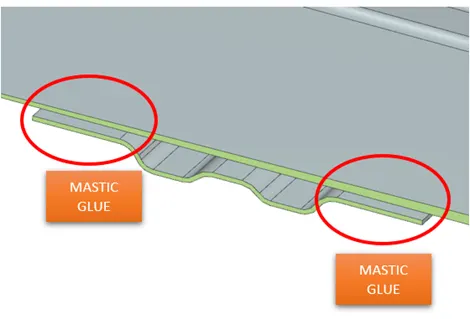
It is the unit available in between centre roof rail and rear roof rail.
It was acting like a stiffener and giving strength to the roof.
It will join with the roof by using mastic glue instead of spot welding to avoid the weld impression.
REAR ROOF RAIL:
It is the unit available at rear side.
Rear door activities need to take while designing.
Total rear door unit weight will withstand at this location only.
It will join with the roof by spot welding on one side and mastic glue process on other side.
FINAL DESIGN OUTPUT:
ADDITIONAL INFORMATION:
- Emboss provided to improves aesthetic look and increase the strength of the smart stylish roof.
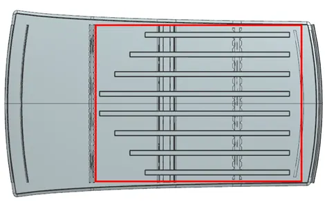
- Cut-out added in the roof rails to decrease the part weight.
- Holes is available in the roof rails for the headliner assembly purpose.
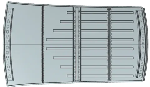
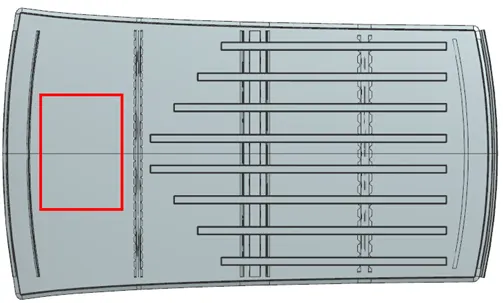
- We can make a cut-out as per below image to assemble the sun roof assy. If required as per standard regulations.
DRAFT ANALYSIS:
- ROOF TOP.
Input given: Limit angle = 5°
Result: Found Ok (Two location found yellow colour and it was conditionally accepted)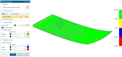
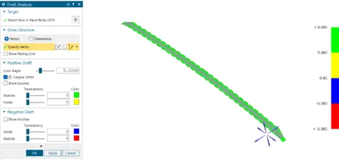
- BOW ROOF-1
Input given: Limit angle = 5°
Result: Found Ok
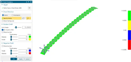
- BOW ROOF-2
Input given: Limit angle = 5°
Result: Found Ok
- FRONT ROOF RAIL
Input given: Limit angle = 5°
Result: Found Ok
Remarks: Default vector found not ok then the vector changed w.r.t the part then found ok.
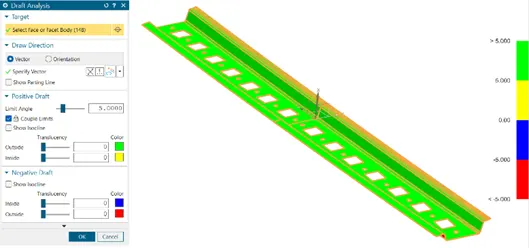
- CENTRE ROOF RAIL TOP
Input given: Limit angle = 5°
Result: Found Ok
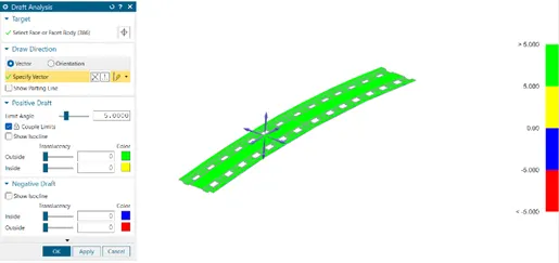
- CENTRE ROOF RAIL BOTTOM
Input given: Limit angle = 5°
Result: Found Ok
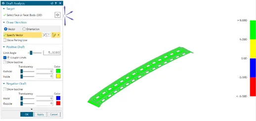
- REAR ROOF RAIL
Input given: Limit angle = 5°
Result: Found Ok
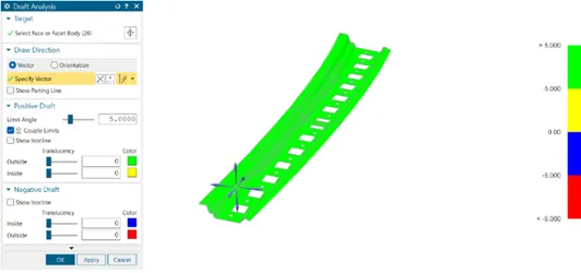
OUTPUT PROFILE:
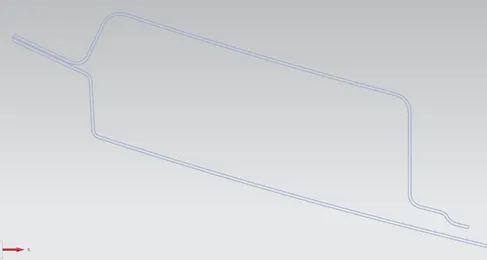
- FRONT ROOF RAIL:
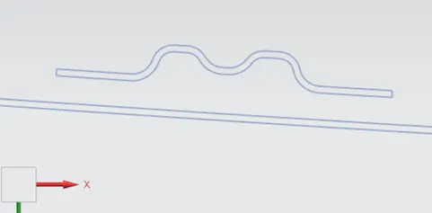
- BOW ROOF-1:
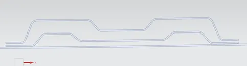
- CENTRE ROOF RAIL:
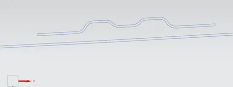
- BOW ROOF-2:
- REAR ROOF RAIL:
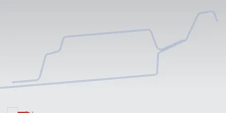
SECTION MODULUS:
- FRONT ROOF RAIL:
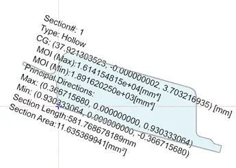
By using output design, we got the value of
MOI (Max) (I Max) = 1.614e+04 mm4
MOI (MIN) (I Min) = 1.891e+03 mm4
Section Length = 581.768 mm
Section Area = 11.635 mm2
Cut Section total length = 124.6 mm
Y = Cut section total length/2 = 124.6/2 = 62.3 mm
S= I Max/Y = 16140/62.3 = 259.069 mm3
S= I Min/Y = 1891/62.3 = 30.35 mm3
- BOW ROOF-1:
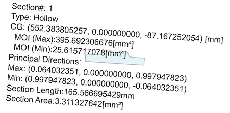
By using output design, we got the value of
MOI (Max) (I Max) = 395.692 mm4
MOI (MIN) (I Min) = 25.615 mm4
Section Length = 165.566 mm
Section Area = 3.311 mm2
Cut Section total length = 35 mm
Y = Cut section total length/2 = 35/2 = 17.5 mm
S= I Max/Y = 385.692/17.5 = 22.039 mm3
S= I Min/Y = 25.615/17.5 = 1.463 mm3
- CENTRE ROOF RAIL TOP:
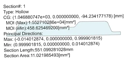
By using output design, we got the value of
MOI (Max) (I Max) = 1.552e+04 mm4
MOI (MIN) (I Min) = 458.625 mm4
Section Length = 551.099 mm
Section Area = 11.021 mm2
Cut Section total length = 125 mm
Y = Cut section total length/2 = 125/2 = 62.5 mm
S= I Max/Y = 1.552e+04 /62.5 = 248.32 mm3
S= I Min/Y = 458.625/62.5 = 7.338 mm3
- CENTRE ROOF RAIL BOTTOM:
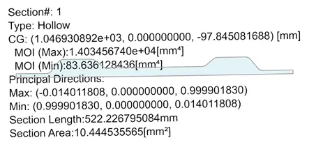
By using output design, we got the value of
MOI (Max) (I Max) = 1.403e+04 mm4
MOI (MIN) (I Min) = 83.63 mm4
Section Length = 522.226 mm
Section Area = 10.444 mm2
Cut Section total length = 125 mm
Y = Cut section total length/2 = 125/2 = 62.5 mm
S= I Max/Y = 1.403e+04 /62.5 = 224.48 mm3
S= I Min/Y = 83.63/62.5 = 1.338 mm3
- BOW ROOF-2:
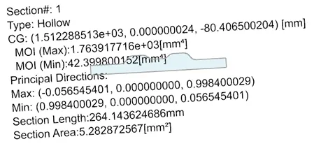
By using output design, we got the value of
MOI (Max) (I Max) = 1.763e+03 mm4
MOI (MIN) (I Min) = 42.399 mm4
Section Length = 264.143 mm
Section Area = 5.282 mm2
Cut Section total length = 60 mm
Y = Cut section total length/2 = 60/2 = 30 mm
S= I Max/Y = 1.763e+03 /30 = 58.766 mm3
S= I Min/Y = 42.399/30 = 1.413 mm3
- REAR ROOF RAIL:
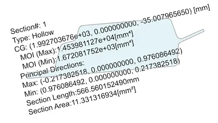
By using output design, we got the value of
MOI (Max) (I Max) = 1.453e+04 mm4
MOI (MIN) (I Min) = 1.672e+03 mm4
Section Length = 566.56 mm
Section Area = 11.331 mm2
Cut Section total length = 120.2 mm
Y = Cut section total length/2 = 120.2/2 = 60.1 mm
S= I Max/Y = 1.453e+04 /60.1 = 241.763 mm3
S= I Min/Y = 1.672e+03/60.1 = 27.82 mm3
ROOF BOW CALCULATION:
HEAT DISTORTION CALCULATION:
To find the heat distortion by using below formula.
W=[1.73x10˄(-3)xL]+[1.85x10˄(-8)x(R˄2)/t]+[1.10x10˄(-3)xl]-2.68
Judgement condition: OK<2.7>3.1
Where,
L = Roof length in “X” direction (mm)
R = Roof curvature (R = 2(Rx*Ry)/(Rx+Ry)
Rx = “X” curvature
Ry = “Y” curvature
t = Roof plate thickness (mm)
l = Bow roof span (mm)
Rx & Ry can be measured from the design
PROCEDURE:
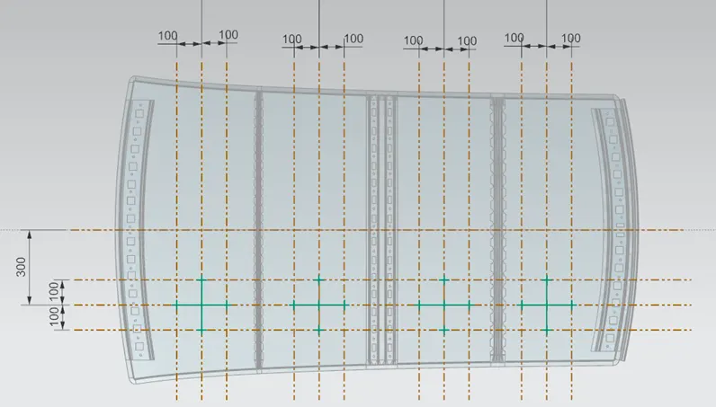
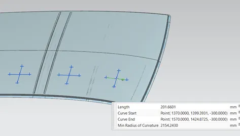
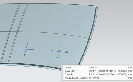
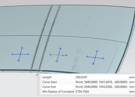
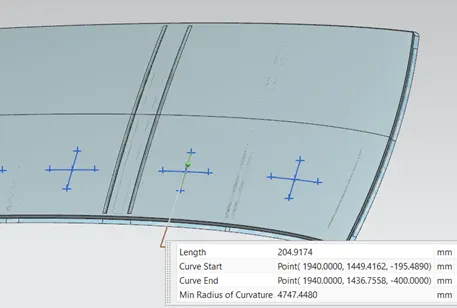
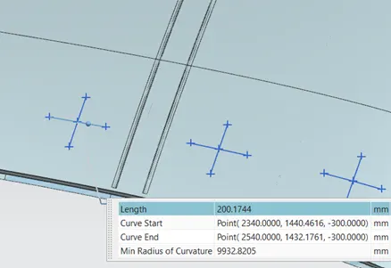
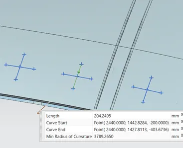
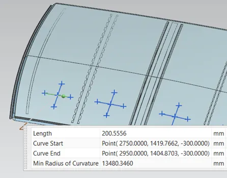
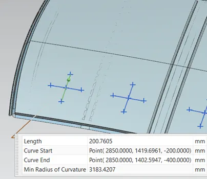
- From centre line draw line below of 300mm and named as “Cx”.
- From Cx draw line above and below of 100mm.
- Draw a centre line vertically in-between roof rails and named as “Cy”.
- From Cy draw line vertically in left and right of 100mm.
- Create a point on intersection of both horizontal and vertical line.
- Create a curve by using intersection points.
- Project the curve on surface to find out the radius.
FROM FRONT RAIL TO BOW ROOF RAIL-1:
Rx = 2154.243 mm
Ry = 5541.596 mm
FROM BOW ROOF RAIL-1 TO CENTRE ROOF RAIL:
Rx = 5704.792 mm
Ry = 4747.448 mm
FROM CENTRE ROOF RAIL TO BOW ROOF RAIL-2:
Rx = 9932.82 mm
Ry = 3789.265 mm
FROM BOW ROOF RAIL-2 TO REAR ROOF RAIL:
Rx = 13480.346 mm
Ry = 3183.42 mm
HEAT DISTORTION RESULT:
|
SL. NO. |
ROOF RAILS |
Rx |
Ry |
R |
t |
l |
L |
W |
RESULT |
|
1 |
FR TO BR-1 |
2154.24 |
5541.59 |
3102.44 |
0.75 |
445.9 |
2094 |
1.67 |
OK |
|
2 |
BR-1 TO CR |
5704.79 |
4747.44 |
5182.27 |
0.75 |
414.5 |
2094 |
2.06 |
OK |
|
3 |
CR TO BR-2 |
9932.82 |
3789.26 |
5485.76 |
0.75 |
372.7 |
2094 |
2.10 |
OK |
|
4 |
BR-2 TO RR |
13480.34 |
3183.42 |
5150.52 |
0.75 |
391.1 |
2094 |
2.03 |
OK |
L = Total length of top roof = 2094.3mm
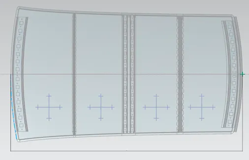
l = Length between roof rails individually
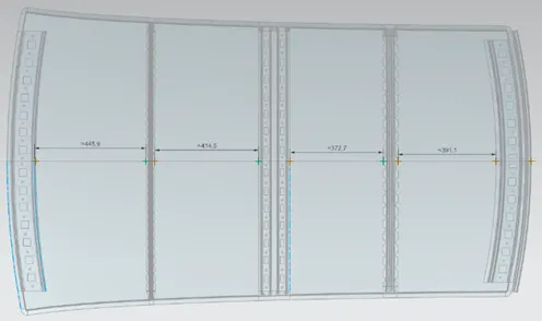
REMARKS:
As per result the value of “W” found ok and comes within the judgement condition.
SNOW LOAD CALCULATION:
It is the calculation to check how much load it was withstanding at the time of snow fall.
Qr=[Iy x t²]/[a x s x [(Rx+Ry)/2]² x 10⁻⁸]
Where,
a = My x Lx² x 10⁻¹²
My = Y(Ly-Y)
Judgement Condition=Qr ≥ 3.1
250 ≤ s ≤ 380
t = Roof plate thickness
Ly = Distance between front and rear roof rails in “Y” direction.
Ly = Distance between left and right end of roof bow.
Y = Distance between the front roof rail to row bow (mm).
s = Distance for which roof bow divided load (mm).
s = (L1/2) + (L2/2)
Iy = Geometrical moment of inertia of the roof bow (“Y” direction cut section) (mm4).
Rx = Curvature radius towards “X” direction (mm).
Ry = Curvature radius towards “Y” direction (mm).
PROCEDURE:
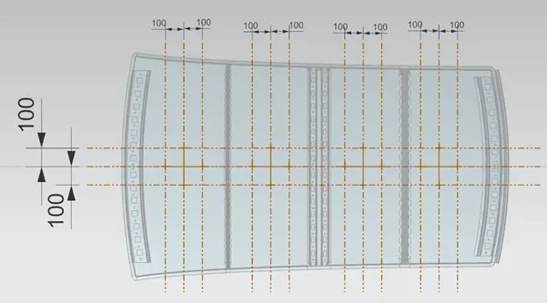
- From Centre line draw a line above and below of 100mm.
- Draw a centre line vertically in-between roof rails and named as “Cy”.
- From “Cy” draw line vertically in left and right of 100mm.
- Create a point on intersection of both horizontal and vertical line.
- Create a curve by using intersection points.
- Project the curve on surface to find out the radius.
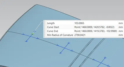
FROM FRONT RAIL TO BOW ROOF RAIL-1:
Rx = 2188.022 mm
Ry = 2790.042 mm
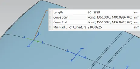
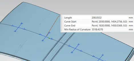
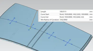
FROM BOW ROOF RAIL-1 TO CENTRE ROOF RAIL:
Rx = 5518.437 mm
Ry = 3162.095 mm
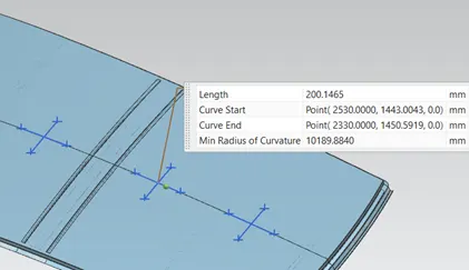
FROM CENTRE ROOF RAIL TO BOW ROOF RAIL-2:
Rx = 10189.884 mm
Ry = 4173.395 mm
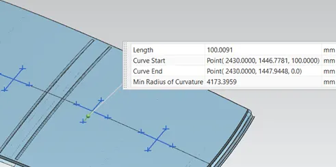
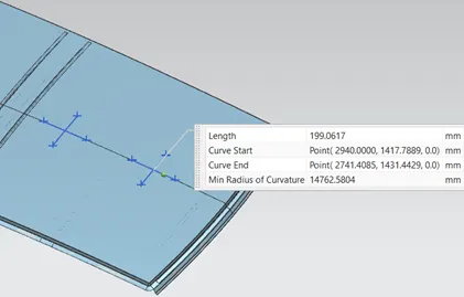
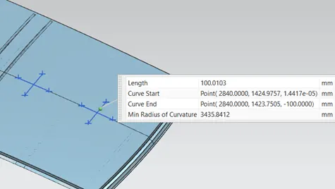
FROM BOW ROOF RAIL-2 TO REAR ROOF RAIL:
Rx = 14762.580 mm
Ry = 3435.841 mm
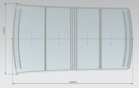
Lx = 2094.6 mm
Ly = 1232.7 mm
BOW ROOF RAIL-1:
Iy = MOI min = 25.615 mm4
CENTRE ROOF RAIL:
Iy = MOI min = 458.625 mm4
ROOF RAIL-2:
Iy = MOI min = 83.63 mm4
VALUE OF L1:
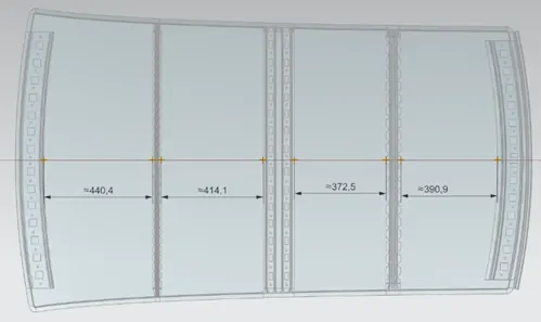
VALUE OF L2:
RESULT:
|
SL. NO. |
ROOF RAILS |
Rx |
Ry |
Iy |
t |
s |
a |
Qr |
"Qr" RESULT |
"s" RESULT |
|
1 |
FR TO BR-1 |
2188.02 |
2790.04 |
25.61 |
0.75 |
443.15 |
1.53 |
426.56 |
OK |
NOT OK |
|
2 |
BR-1 TO CR |
5518.43 |
3162.09 |
458.62 |
0.75 |
414.3 |
1.48 |
4823.20 |
OK |
NOT OK |
|
3 |
CR TO BR-2 |
10189.88 |
4173.39 |
83.63 |
0.75 |
372.6 |
1.40 |
625.25 |
OK |
OK |
REMARKS:
As per result of snow load criteria for “Qr” judgment condition found ok and “s” judgment condition found not ok for Bow roof-1 and centre roof rail.
We need to inform to stylish team to redesign the both roof rails to get ok with the judgement condition.