Roof challenge
AIM:
To Design and Develop a Reinforcements for the given Roof Design submitted by the styling team as per the master sections and parameters.
AGENDA:
- To design the Reinforcements and Flanges for the given roof design.
- To perform curvature study and calculate the position for the Bow Roof Rail.
- To determine the Head distorsion creteria of the car's roof.
- To determine the section modulus along the 0-Y section of the Roof.
- To determine the Snow load criteria of the Roof.
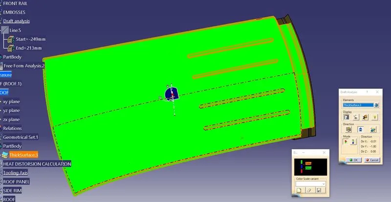
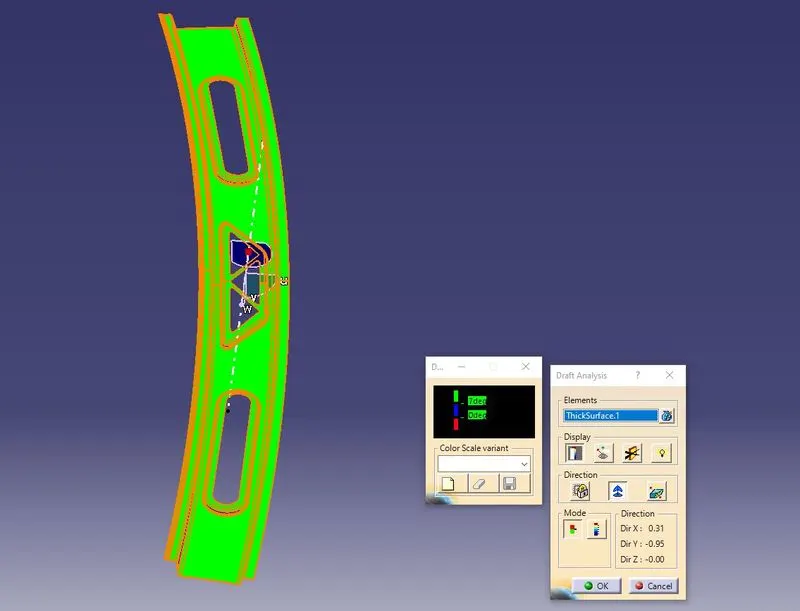
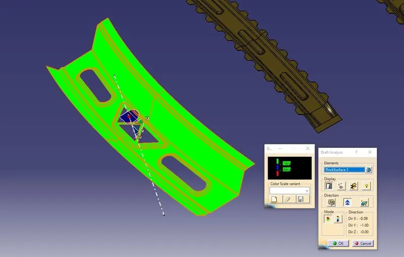
- To perform Draft Analysis on the the components developed.
THESIS:
An automobile roof or car top is the portion of an automobile that sits above the passenger compartment, protecting the vehicle occupants from sun, wind, rain, and other external elements. Because the earliest automobiles were designed in an era ofHorse drawn, early automobile roofs used similar materials and designs.
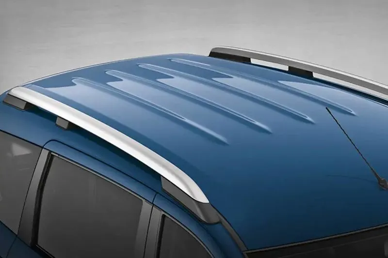
Types of car roofs:
- Convertible roofs.
- Hardtops.
- Sunroofs.
- T-tops.
- Targa tops.
- Vinyl roofs.
Roof Strength Metrics:
Because performance in the FMVSS 216 test has not been shown to affect injury risk, it is not
clear that a baseline SWR within 5 inches of plate displacement better predicts injury outcome than other
strength metrics that can be calculated from the same test data. The energy absorbed by the roof may be
more relevant to injury risk than the peak force it can withstand, or the roof’s performance over a plate
displacement other than 5 inches could better predict injury risk. The contribution of vehicle mass to
rollover crashworthiness also is unknown.
In the present study the following metrics were evaluated: peak force, SWR, energy absorbed,
and equivalent drop height. SWR is peak force divided by vehicle curb weight, and equivalent drop
height is energy divided by curb weight converted to inches. The term “equivalent drop height” is used
because this metric can be considered the height from which the vehicle could be dropped on its roof to
produce the same level of crush as observed in the test (under an ideal condition where the roof deforms
identically in the dynamic and quasi-static conditions). Each of the metrics was calculated within 2, 5,
and 10 inches of plate displacement. Two inches was chosen based on the highly linear characteristic of
the force-deflection curves up to this displacement. Ten inches represented the maximum deflection in 10
of the 11 tests.
Because there were 11 tested roof designs, the evaluations using peak force and energy
absorption had 11 available values for comparison. The use of curb weight for calculating SWR and
equivalent drop height produced many more unique values. Corporate twins were separated where curb
weights differed, and two-wheel drive vehicles were separated from four-wheel drive versions due to their
lower weights and varying SSF values. These 31 vehicles produced 28 unique values of SWR and
equivalent drop height. Table 1 lists the vehicle test data used in the analysis. Appendix A reports the
other metrics for these vehicles as well as the other models for which these data can be applied. The
results for the 1996-2001 Ford Explorer and Mercury Mountaineer reflect the use of averaged values
obtained from two tests. The Mitsubishi Montero Sport was omitted from the 10-inch displacement
evaluations because NHTSA’s test of this vehicle did not continue beyond 7.4 inches. This omission did
not substantially affect the results; the Montero Sport had the smallest exposure of all vehicles in the
study.
Design considerations:
- Visibility criteria
- Head clearance
- Heat distortion
- Snow load criteria
- Draft analysis
- Section Modulus
Recieved Inputs:
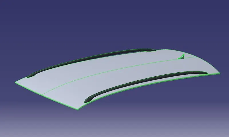
we have recieved inputs of the Class-A surface of the roof along with master sections, which has to be converted into a fully functional component according to the FMVSS-216 standards.
Class-A image:
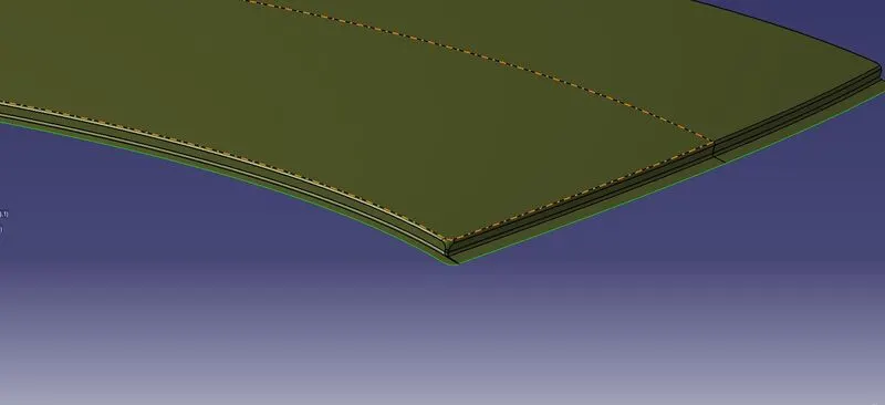
Creation of Ditch area:
Creation of Front Roof Rail.
The front roof rail has to be created according to the given Master section received from the Styling Department.
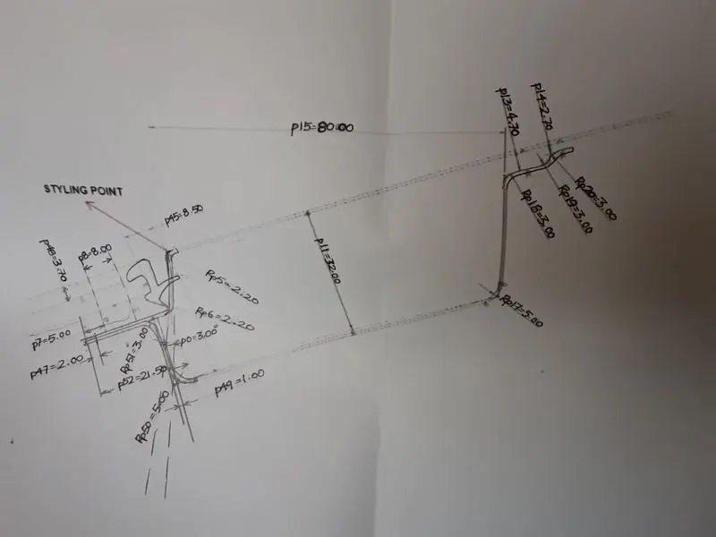
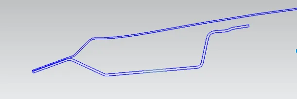
Created Front roof Rail:
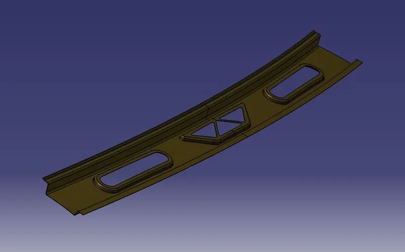
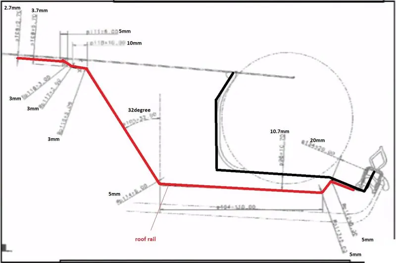
Creation of Rear Roof Rail:
The rear Roof Rail also has to be created according to the master sections received from the styling department:
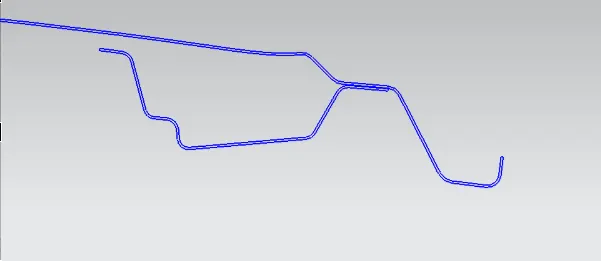
Created Rear Roof Rail:
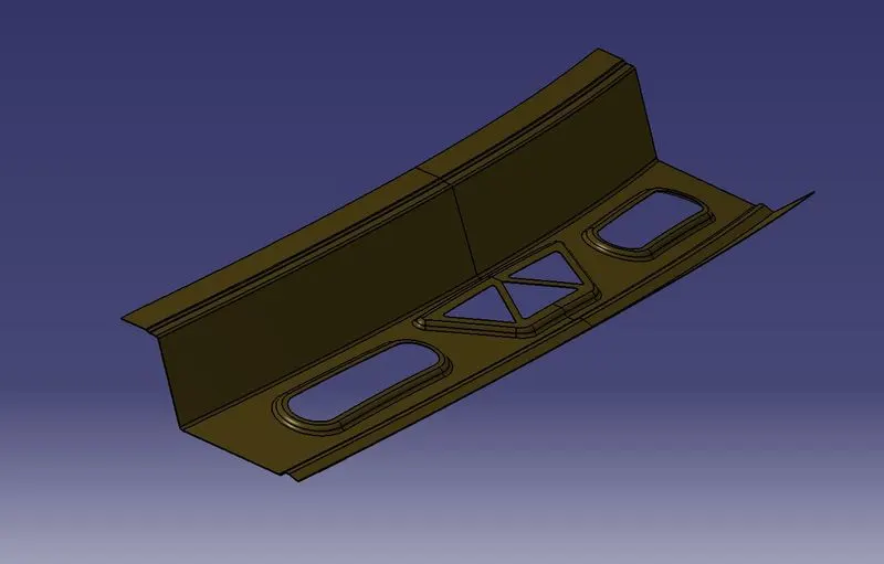
Creation of the Center roof rail:
The center roof rail has a free use of dimensions within the allowed limtis until it follows the Master section received from the Styling Department.
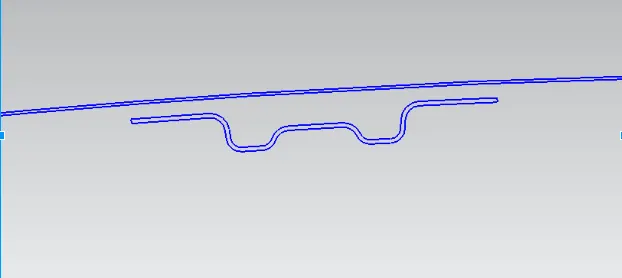
Created Center Roof Rail:
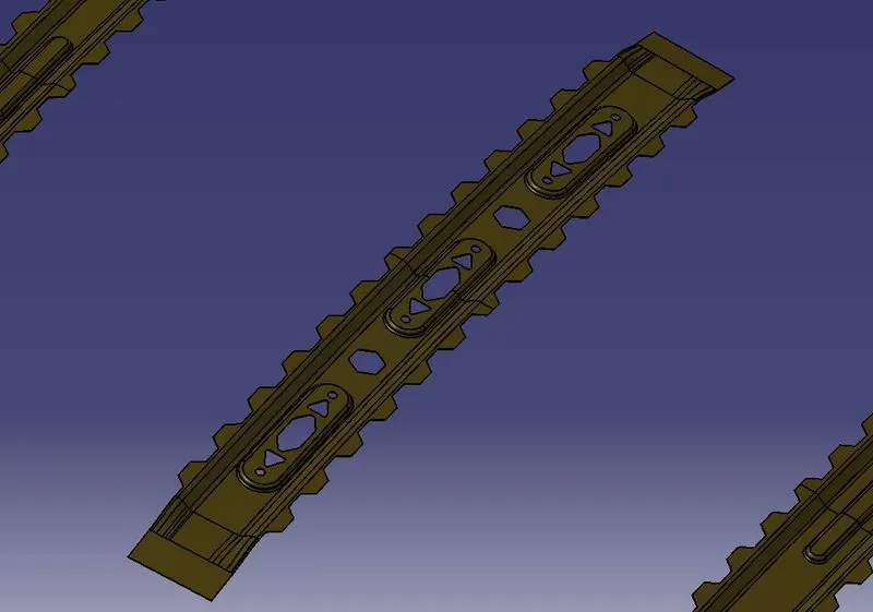
Creation of Bow Roof Rails:
The bow roof rails have to be designed according to the FMVSS 216 standards inorder to meet the Snow load criteria. as long as the roof meets the safety standards, the design of the bow Roof rails is free upon to the choice of the design within the parameters in this case.
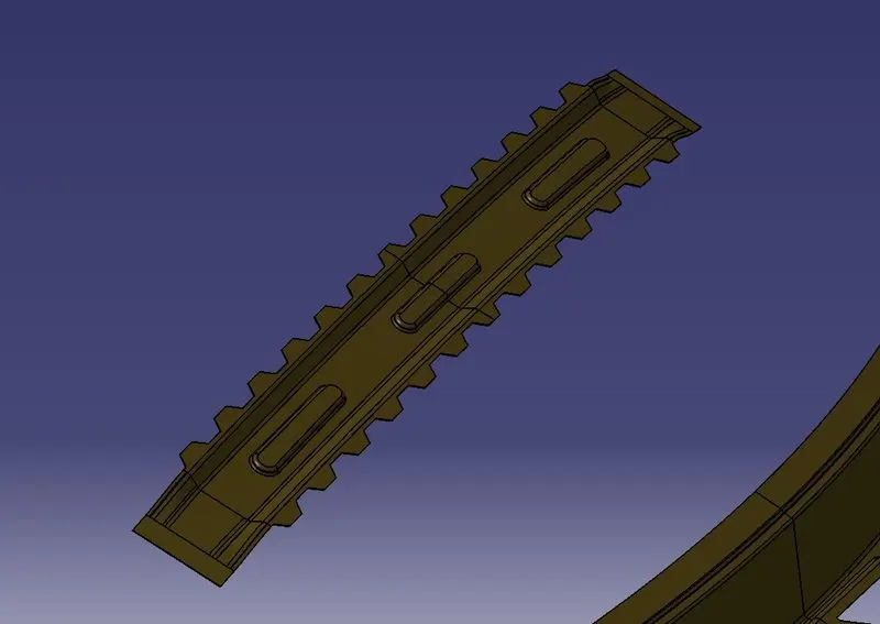
Bow Roof Rail 1:
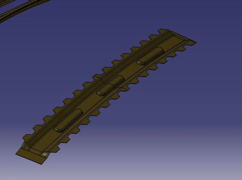
Bow Roof Rail 2:
Calculations for Heat Distorsion:
The heat deflection temperature or heat distortion temperature (HDT, HDTUL, or DTUL) is the temperature at which a material sample deforms under a specified load.
W = [1.73 x 10^(-3) x L] + [1.85 x 10^(-8) x (R^2)/t] + [ 1.10x10^(-3) x l] - 2.68
Judgement Condition : OK< 2.7> 3.1
Where
L = Roof Length in X-Direction[mm](Roof dimension in 0-Y)
R = Roof curvature
R = 2(Rx*Ry)/(Rx+Ry)
Rx = X curvature
Ry = Y curvature
t = Roof plate thickness [mm]
l = Bow Roof Span [mm]

Snow load Criteria:
The maximum snow load of your roof depends on several factors, but the average roof can support about 20 pounds of snow per square inch. However, some areas of the U.S. that are prone to lots of snow may have roofs that support a heavier snow load. If the roof holds more weight than this, it can cause damage.
Qr = [Iy x t2] / [α x s x [(Rx + Ry)/2]2 x 10-8]
Note: The Qr value given over here is correct. There was a typo error in the formula given in the video.
Where
α = My x Lx2 x 10-12 , My = Y(Ly-Y)
Judgement condition = Qr ≥ 3.1
250 ≤ s ≤ 380
t = Roof plate thickness [mm]
Ly = Distance between the front and rear roof Rails on the Vehicle along with 0Y[mm]
Length of Roof panel with the center point between Roof rail Front /Rear as the front and rear reference point.
Lx = Distance between the Left and Right end of the roof on the Roof BOW [mm]
Width of the roof panel exposed on the surface.
Y = Distance front Front Roof Rail to Roof BOW[mm]
s = Distance for which Roof BOW bears divided load [mm]
s = L1/2 + L2/2
Iy = Geometrical moment of inertia of Roof BOW (Y cross-section )[mm4]
Rx = Lateral direction curvature radius of roof panel Y cross-section on Roof BOW [mm]
Roof panel curvature Radius of the Length Lx in Front view
Ry = Longitudinal Direction curvature radius of the Roof panel X cross-section on Roof BOW [mm]
Roof panel X curvature radius of length s in Side view

Draft Analysis:
Draft Analysis of the Roof Outer panel:
Draft Analysis of the Front Roof Rail:
Draft Analysis of the Rear Roof Rail:
Draft analysis of the Center Roof Rail:
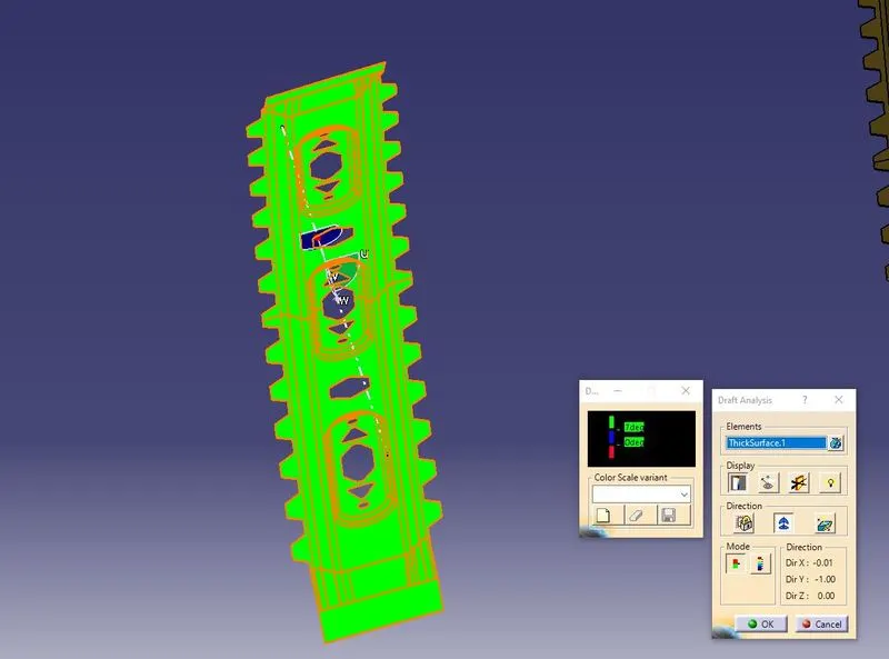
Draft Analysis of the Bow Roof 1:
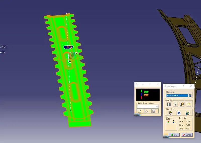
Draft Analysis of the Bow Roof 2:
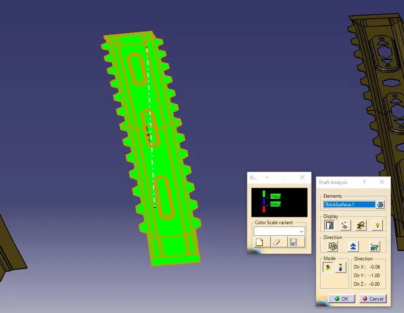
Section Moduli of the Components of the Roof:
Section Modulus of the Front Roof Rail:
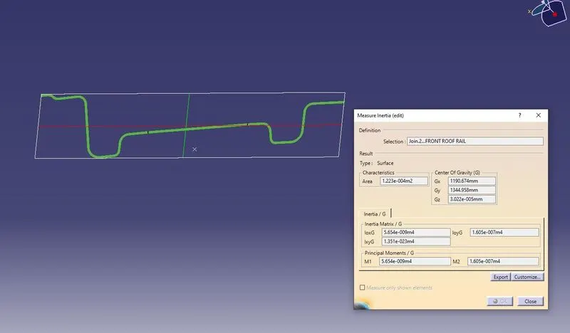
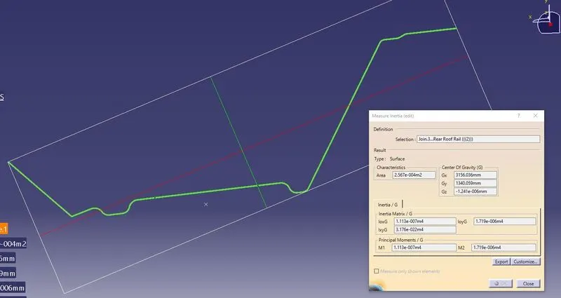
Section Modulus of the Rear Roof Rail:
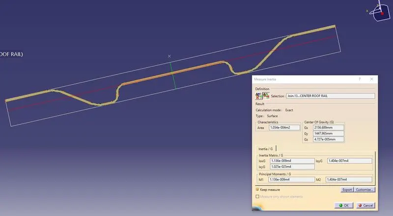
Section Modulus of the Center Roof Rail:
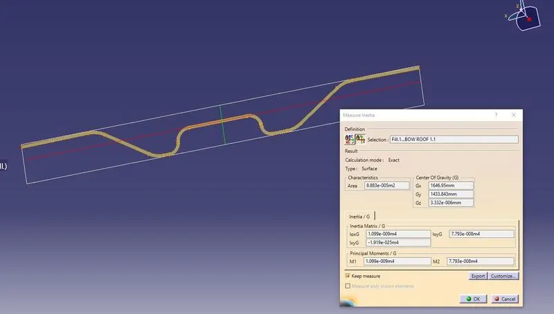
Section Modulus of the Bow Roof Rail 1:
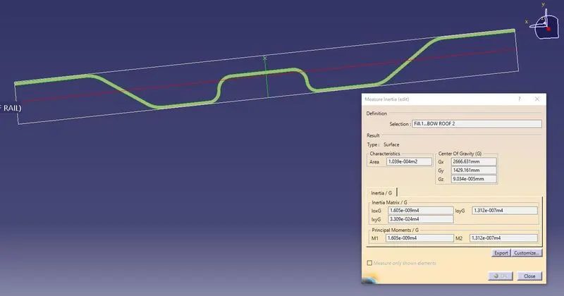
Section Modulus of the Bow Roof Rail 2:
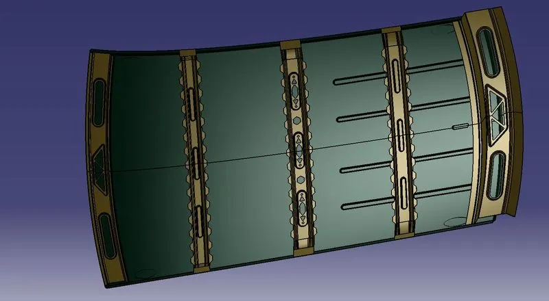
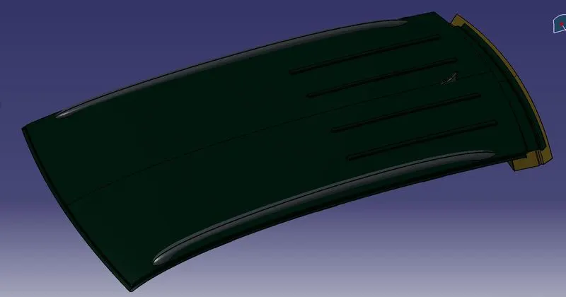
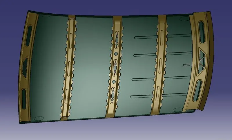
Final Images of the Complete Roof assembly:
CONCLUSION:
The Class-A design submitted by the Styling Department was created into a fully functional component complying with the various FMVSS 216 standards. the component has passed all the design considerations and is ready for Analysis after which it can be further send for manufacturing.