Roof challenge
Objective:
- For the Given Roof styling, develop the essential flanges and reinforcements.
- Creation of Roof ditch area with tool opening angle of 3 degree.
- Provide appropriate dimensions and validate for Draft analysis.
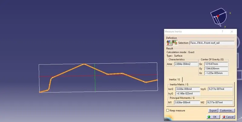
- Section modulus study on 0-Y section for the Master sections created for Front roof rail, Rear roof rail, and Bow Roof Rails.
- Perform curvature study on the roof and calculations to determine the position of the Bow-roof.
Theory:
Roof or car top is the portion of an automobile that sits above the passenger compartment, protecting the vehicle occupants from sun, wind, rain, and other external elements. Car Roof consists of Roof panel with reinforcements like front Roof rail, Rear Roof rail, Bow roof rails.
Front Roof rail joins the roof panel with Windshield glass and body side panel and also this Front roof rail used for the bracket map lamp and room lamp mountings where as Rear Roof rail joins the Backdoor and body side panel of the car.
Bow Roofs provides the additional strength to the Roof panel in order to withstand the forces acts on the Roof, Bow Roofs joins with the Roof outer panel and the body side panels and these Bow Roofs positioned in the most flat areas of the outer roof panel.
Below mentioned are some of the famous Roof Types in the Market:
- Hard Tops:A rigid form of Roof, typically constructed from metal.
- Sunroofs: An operable window in a Roof, which allows light or fresh air into the car
- Convertible: Allows an open-air driving experience, with the ability to provide a roof when required.
Design Considerations:
Thickness and manufacturing requirements:
- Thickness of Roof panel: 0.75mm
- Reinforcement Thickness = 0.75mm
- Tool opening angle 3 degree
- Emboss depth should not exceed 6mm.
- Minimum filet radius should be more than the 3+thickness
- No sharp corners inside the component
Functional requirements:
- Provide adequate clearance for the windshield glass joining for joining with Roof at Front
- Visibility criteria of windshield glass at front Roof rail
- Rear visibility criteria for Rear Roof Rail
- Head impact zone or head room clearance based on the trim parts.
- Mastic clearance to join the reinforcements.
Procedure:
- Roof Outer Panel:
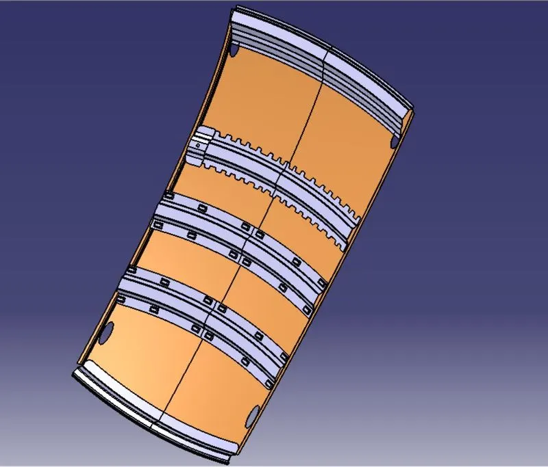
By taking the input styling surface of roof panel then first created the flanges or the ditch area at the four sides with the required open angle of 3 degree. At the front end of the roof panel we have given the flange length of 21.5mm to provide the enough clearance for the windshield and its associated components like rubber sealant. The rear end also created the flanges with the required length and opening angle to allow the joining for the backdoor .Additional beads created on the top of roof panel to increase the strength of the panel.
- Front Roof Rail:
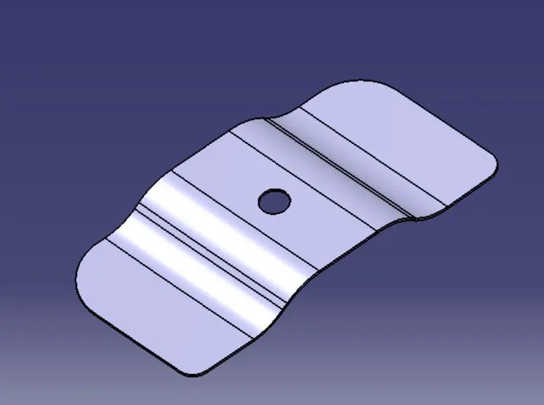
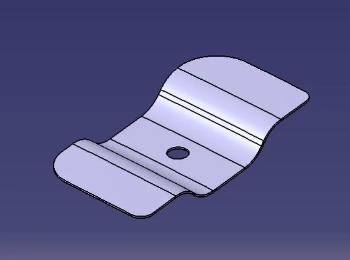
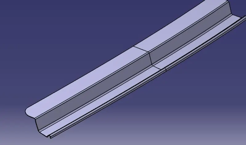
Front Roof rail is the reinforcement for the roof outer panel and as well as it joins the Roof panel with the Windshield glass and body side panel and also supports the bracket map lamp and room lamp mounting. Front roof rail created based on the master section which is developed with above mentioned functional requirements of tool opening angle, required clearance for to join with the windshield glass, visibility criteria, the deepness based on the head room clearances and the clearance mastic joining. See the below master section used for the Front Roof Rail and the Front roof rail design based on the master section. - Rear Roof Rail:
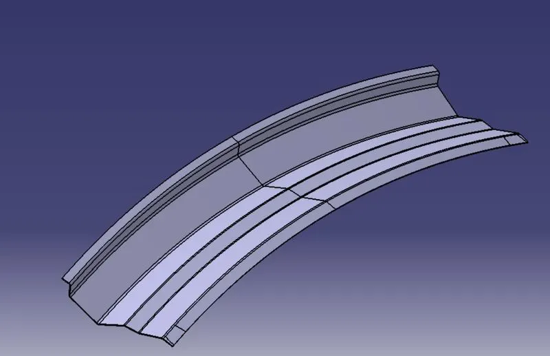
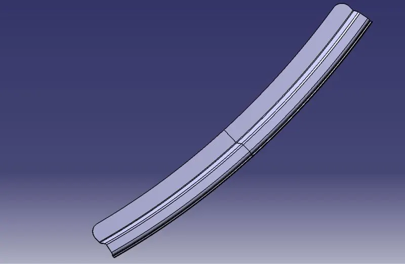
Rear Roof rail is also the reinforcement for the outer panel and it joins the backdoor and the body side outer. For designing the Rear roof rail also we have developed a master section based on the functional requirements which are Rear visibility criteria, Rear head room clearance, Tool opening and mastic clearance. See the below image of Rear Roof rail design. - Bow Roof Rails at Centre, Front and Rear:
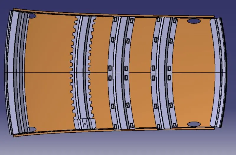
Bow Roof Rails are also the reinforcements of outer panel and are used to strengthen the roof panel and these joins to the Roof panel with the help of mastic sealant to the roof panel and connects to the body side using the spot welding technique. These are designed based on the developed master sections developed using the criteria of Visibility and the head room clearance. And the position of these Bow roofs are mostly recommend to place at the flat portions of the Roof outer panel.
Draft Analysis of Roof Design:
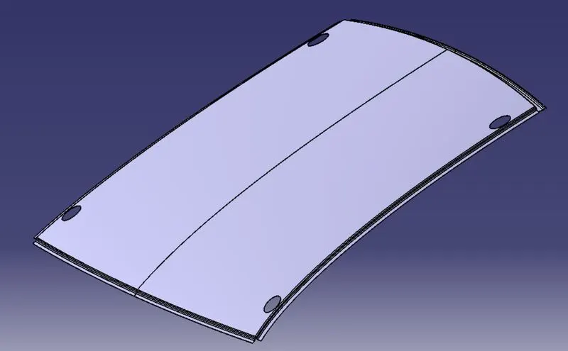
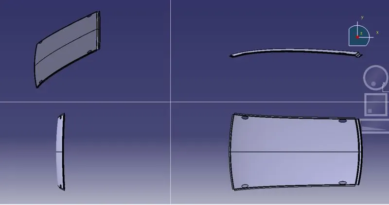
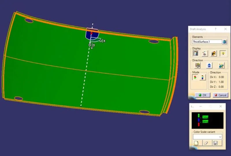
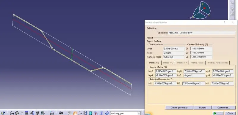
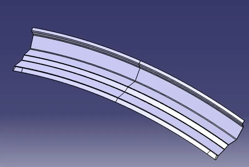
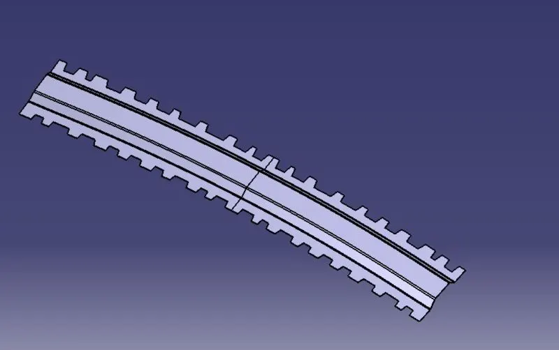
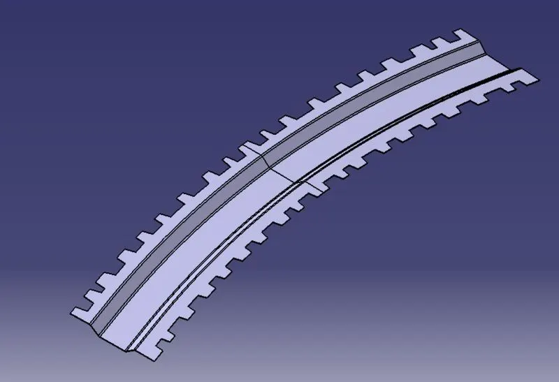
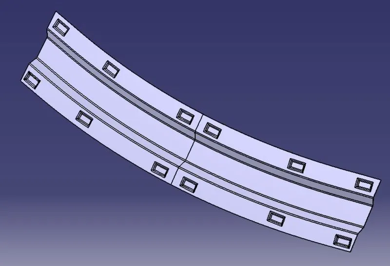
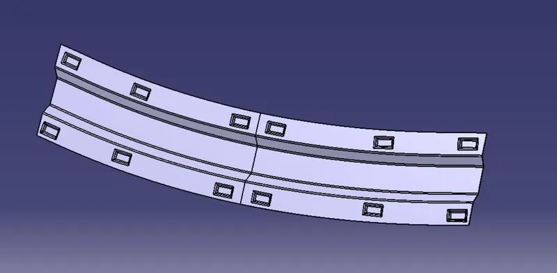
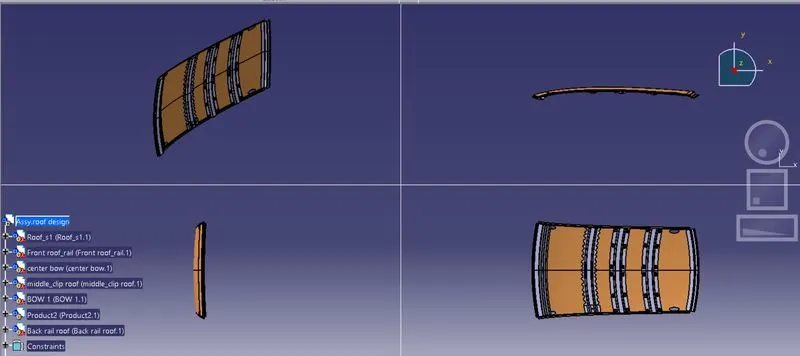
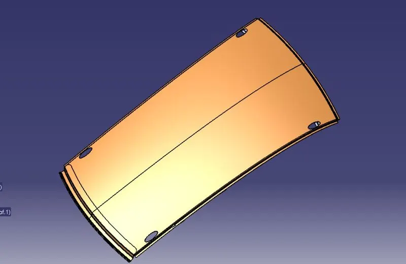
To check for draft analysis, used the Draft analysis command in the Catia. For this created one line in the Tooling direction and placed the compass in the tooling direction and locked the orientation and selected part. Then the draft analysis result is green for all parts with 3degree angle as shown below so the design of of all parts are staisfied as per the draft analysis. See the below images for your reference.
CALCULATING HEAT DISTORTION CRITERIA
W = [1.73 x 10^(-3) x L] + [1.85 x 10^(-8) x (R^2)/t] + [ 1.10x10^(-3) x l] - 2.68
Judgement Condition : OK< 3.1
Where
L = Roof Length in X-Direction[mm](Roof dimension in 0-Y)
R = Roof curvature
R = 2(Rx*Ry)/(Rx+Ry)
Rx = X curvature
Ry = Y curvature
t = Roof plate thickness [mm]
l = Bow Roof Span [mm]
CALCULATIONS:
1. FOR FRONT RAIL ROW TO BOW ROW 1
W = [1.73 x 10^(-3) x L] + [1.85 x 10^(-8) x (R^2)/t] + [ 1.10x10^(-3) x l] - 2.68
L = 2033.705mm
t = 0.75mm
Rx = 2803.388mm (by measuring the X-direction arc )
Ry = 5759.619mm (by measuring the Y-direction arc)
l = 313.199mm (distance between extreme ends of front rail row and bow row 1)
R = 2(Rx*Ry)/(Rx+Ry)
= 2(2803.388*5759.619)/(2803.388+5759.619)
= 3771.209mm
(R^2)/t = (3771.209^2)/0.75
= 18962689.762
W = [1.73 x 10^(-3) x 2033.705] + [1.85 x 10^(-8) x 18962689.762] + [1.10 x 10^(-3) x 313.199] - 2.68
= 1.532
so the value is less than 3.1
Judgement Condition : OK< 3.1
2. BOW ROOF 1 & CENTRE REINFORCEMENT
W = [1.73 x 10^(-3) x L] + [1.85 x 10^(-8) x (R^2)/t] + [ 1.10x10^(-3) x l] - 2.68
L = 2033.705mm
t = 0.75mm
Rx = 4946.194mm (by measuring the X-direction arc )
Ry = 6306.001mm (by measuring the Y-direction arc)
l = 329.33mm (distance between extreme ends of bow row 1 & centre reinforcement)
R = 2(Rx*Ry)/(Rx+Ry)
= 2(4946.194*6306.001)/(4946.194+6306.001)
= 5543.932mm
(R^2)/t = (5543.932^2)/0.75
= 40980245.774
W = [1.73 x 10^(-3) x 2033.705] + [1.85 x 10^(-8) x 40980245.774] + [1.10 x 10^(-3) x 329.33] - 2.68
= 1.958
so the value is less than 3.1
Judgement Condition : OK< 3.1
3. CENTRE REINFORCEMENT & BOW ROOF 2
W = [1.73 x 10^(-3) x L] + [1.85 x 10^(-8) x (R^2)/t] + [ 1.10x10^(-3) x l] - 2.68
L = 2033.705mm
t = 0.75mm
Rx = 4012.304mm (by measuring the X-direction arc )
Ry = 10436.981mm (by measuring the Y-direction arc)
l = 329.37mm (distance between extreme ends of centre reinforcement & bow roof 2)
R = 2(Rx*Ry)/(Rx+Ry)
= 2(4012.304*10436.981)/(4012.304+10436.981)
= 5796.320mm
(R^2)/t = (5796.320^2)/0.75
= 44796434.910
W = [1.73 x 10^(-3) x 2033.705] + [1.85 x 10^(-8) x 44796434.910] + [1.10 x 10^(-3) x329.37] - 2.68
= 2.006
so the value is less than 3.1
Judgement Condition : OK< 3.1
- BOW ROOF 2 & REAR ROOF ROW
W = [1.73 x 10^(-3) x L] + [1.85 x 10^(-8) x (R^2)/t] + [ 1.10x10^(-3) x l] - 2.68
L = 2033.705mm
t = 0.75mm
Rx = 3324.853mm (by measuring the X-direction arc )
Ry = 14407.706mm (by measuring the Y-direction arc)
l = 315.32mm (distance between extreme ends of bow roof 2 &rear roof row)
R = 2(Rx*Ry)/(Rx+Ry)
= 2(3324.853*14407.706)/(3324.853+14407.706)
= 5402.886mm
(R^2)/t = (5402.886^2)/0.75
= 38921575.302
W = [1.73 x 10^(-3) x 2033.705] + [1.85 x 10^(-8) x 38921575.302] + [1.10 x 10^(-3) x315.32] - 2.68
= 1.904
so the value is less than 3.1
Judgement Condition : OK< 3.1
Table for all the values of Heat distortion criteria:
|
POSITIONS |
Rx (mm) |
Ry (mm) |
R (mm) |
l (mm) |
L (mm) |
t (mm) |
R^2/t |
W |
OK/NG |
||
|
FRR & BR1 |
5759.619 |
2803.388 |
3771.209 |
313.199 |
2033.705 |
0.75 |
18962689.762 |
1.532 |
OK |
||
|
BR1 & CR |
4946.194 |
6306.001 |
5543.932 |
329.33 |
2033.705 |
0.75 |
40980245.774 |
1.958 |
OK |
||
|
CR & BR2 |
4012.304 |
10436.981 |
5796.320 |
329.37 |
2033.705 |
0.75 |
44796434.910 |
2.006 |
OK |
||
|
BR2 & RRR |
3324.853 |
14407.706 |
5402.886 |
315.32 |
2033.705 |
0.75 |
38921575.302 |
1.904 |
OK |
||
CALCULATING SNOW LOAD CRITERIA
Snow load Prediction formula
Qr = [Iy x t2] / [α x s x [(Rx + Ry)/2]2 x 10-8]
Where
α = My x Lx2 x 10-12 , My = Y(Ly-Y)
Judgement condition = Qr ≥ 3.1
250 ≤ s ≤ 380
t = Roof plate thickness [mm]
Ly = Distance between the front and rear roof Rails on the Vehicle along with 0Y[mm]
Length of Roof panel with the center point between Roof rail Front /Rear as the reference point of the front and the rear.
Lx = Distance between the Left and Right end of the roof on the Roof BOW [mm]
Width of the roof panel exposed on the surface.
Y = Distance front Front Roof Rail to Roof BOW[mm]
s = Distance for which Roof BOW bears divided load [mm]
s = L1/2 + L2/2
Iy = Geometrical moment of inertia of Roof BOW (Y cross-section )[mm4]
Rx = Lateral direction curvature radius of roof panel Y cross-section on Roof BOW [mm]
Roof panel curvature Radius of the Length Lx in Front view
Ry = Longitudinal Direction curvature radius of the Roof panel X cross-section on Roof BOW [mm]
Roof panel X curvature radius of length s in Side view
CALCULATIONS
- FOR FRONT RAIL AND BOW ROW 1
Qr = [Iy x t2] / [α x s x [(Rx + Ry)/2]2 x 10-8]
α = My x Lx2 x 10-12
My = Y(Ly-Y)
s = L1/2 + L2/2
Where
Rx = 4419.102mm
Ry = 2828.46mm
Lx = 1135.145mm
Ly = 2033.705mm
Y = 454.763mm
t = 0.75mm
Iy = 1.23 x 10^4
My = 454.763(2033.705-454.763)
= 718044.400mm
α = 718044.400 x (1135.145)^2 x 10^-12
= 0.925
s = L1/2 + L2/2
L1 = 454.763mm
L2 = 489.459mm
s = (454.763/2) + (489.459/2)
= 472.111mm
Qr = [1.23 x 10^4 x 0.75^2] / [0.925 x 472.111 x[(4419.102+2828.46)/2]^2 x 10^-8
= 120.649
Judgement condition = Qr ≥ 3.1
The Qr value is greater than 3.1
- FOR BOW ROOF 1 AND CENTRE REINFORCEMENT
Qr = [Iy x t2] / [α x s x [(Rx + Ry)/2]2 x 10-8]
α = My x Lx2 x 10-12
My = Y(Ly-Y)
s = L1/2 + L2/2
Where
Rx = 3770.72mm
Ry = 6218.89mm
Lx = 1089.304mm
Ly = 2033.705mm
Y = 489.459mm
t = 0.75mm
Iy = 2.206 x 10^5
My = 489.459(2033.705-489.459)
= 755845.102mm
α = 755845.102 x (1089.304)^2 x 10^-12
= 0.896
s = L1/2 + L2/2
L1 = 489.459mm
L2 = 483.168mm
s = (489.459/2) + (483.168/2)
= 486.313mm
Qr = [2.206 x 10^5 x 0.75^2] / [0.896 x 486.313 x[(3770.72+6218.89)/2]^2 x 10^-8
=1141.485
Judgement condition = Qr ≥ 3.1
the value is greater than 3.1
- CENTRE REINFORCEMENT & BOW ROOF 2
Qr = [Iy x t2] / [α x s x [(Rx + Ry)/2]2 x 10-8]
α = My x Lx2 x 10-12
My = Y(Ly-Y)
s = L1/2 + L2/2
Where
Rx = 4265.151mm
Ry = 10901.41mm
Lx = 1062.38mm
Ly = 2033.705mm
Y = 483.168mm
t = 0.75mm
Iy = 1.27 x 10^4
My = 483.168(2033.705-483.168)
= 749169.861mm
α = 749169.861 x (1062.38)^2 x 10^-12
=0.845
s = L1/2 + L2/2
L1 = 483.168mm
L2 = 487.446mm
s = (483.168/2) + (487.446/2)
=485.307mm
Qr = [1.27 x 10^4 x 0.75^2] / [0.845 x 485.307 x[(4265.151+10901.41)/2]^2 x 10^-8
= 30.294
Judgement condition = Qr ≥ 3.1
the value is greater than 3.1
table for all the values of snow load criteria
|
S. NO |
POSITION |
Rx (mm) |
Ry (mm) |
Lx (mm) |
Ly (mm) |
t (mm) |
Y (mm) |
My = Y(Ly-Y) (mm) |
α = My x Lx2 x 10-12 |
L1(mm) |
L2 (mm) |
s = L1/2 + L2/2 |
Iy (mm^4) |
Qr |
OK/NG |
|
1 |
FRR & BR1 |
4419.102 |
2828.46 |
1135.145 |
2033.705 |
0.75 |
454.763 |
718044.400 |
0.925 |
454.763 |
489.459 |
472.111 |
1.23*10^4 |
120.64 |
OK |
|
2 |
BR1 & CR |
3770.72 |
6218.89 |
1089.304 |
2033.705 |
0.75 |
489.459 |
755845.102 |
0.896 |
489.459 |
483.168 |
486.313 |
2.206*10^5 |
1141.48 |
OK |
|
3 |
CR & BR 2 |
4265.151 |
10901.41 |
1062.38 |
2033.705 |
0.75 |
483.168 |
749169.861 |
0.845 |
483.168 |
487.446 |
485.307 |
1.27*10^4 |
30.294 |
OK |
|
4 |
BR2 & RRR |
4058.865 |
16142.957 |
1047.891 |
2033.705 |
0.75 |