Design And Analysis of Automotive Roof
Objective:
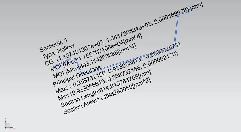
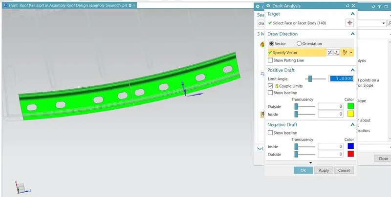
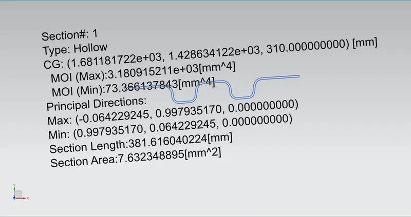
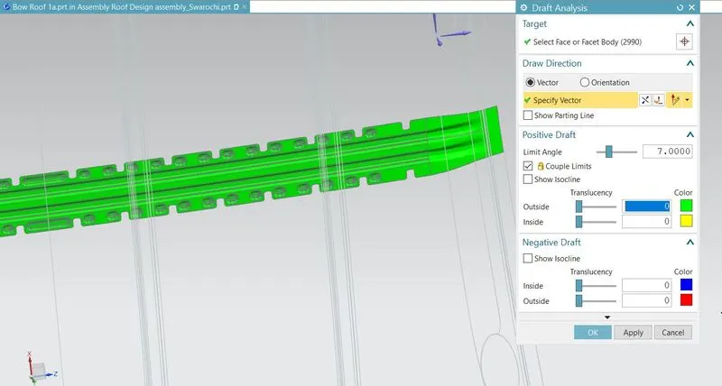
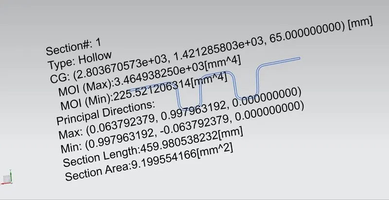
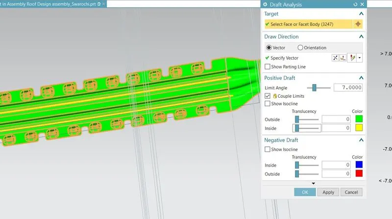
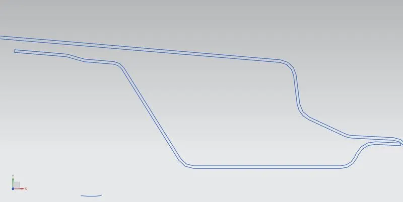
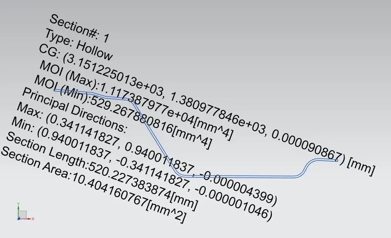
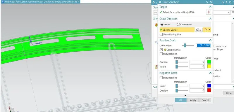
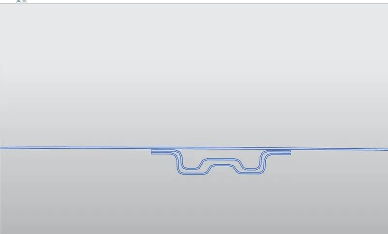
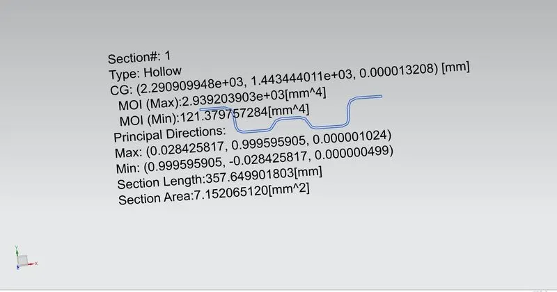
- For the Given Roof styling, Develop the essential flanges and reinforcements, Provide appropriate dimensions and check for Draft analysis, and submit your Section Inertia report on the 0-Y section
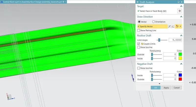
- Starting with the creation of a roof ditch area the tool opening angle is only 3 degrees. Performing curvature study on the roof and perform calculations to determine the position of the Bow-roof
Roof:
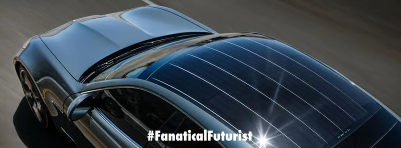
- An automobile roof or car top is the portion of an automobile that sits above the passenger compartment, protecting the vehicle occupants from sun, wind, rain, and other external elements.
Design Considerations:
- Visibility Criteria
- Drip Area
- Head Clearance
- Curvature Study
- Heat Distortion And Snow Load Criteria
- Material Thickness
Ditch Area:
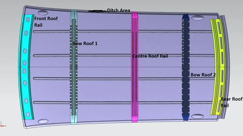
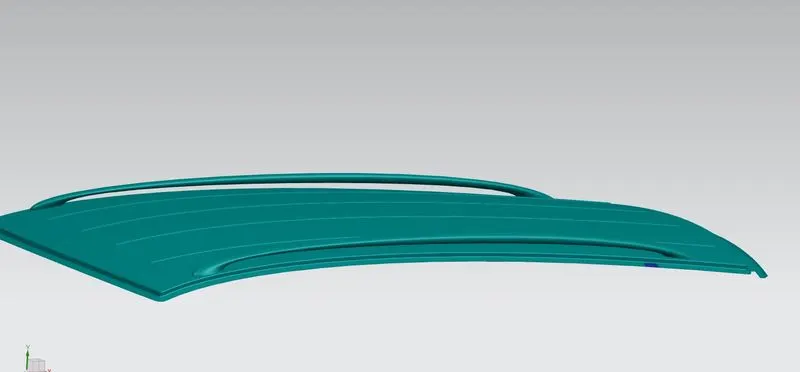
- A roof ditch area extending in a generally longitudinal direction of a vehicle is fixedly coupled to a body member and forms a longitudinal water management channel on a lateral side portion of the roof of the vehicle. It is a styling orient part, so it is produced in-house only. The ditch area may or may not having embossed at the top.
Design Models and Draft Analysis:
Front Roof Rail:
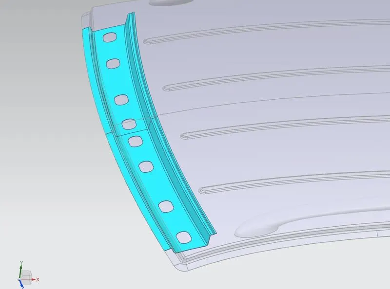
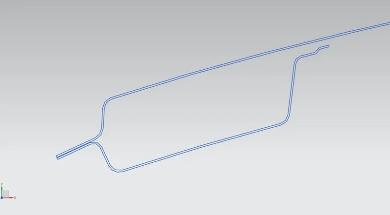
- Front roof rails are used in the assembly of a roof in which it provides mounting provisions to windshield glasses and the changes in the front roof rail influences the frontal visibility of the passenger. The major design factor considered is headroom clearance. The front roof rail also provides provisions for mounting the inside rearview mirror.
Bow Roof:
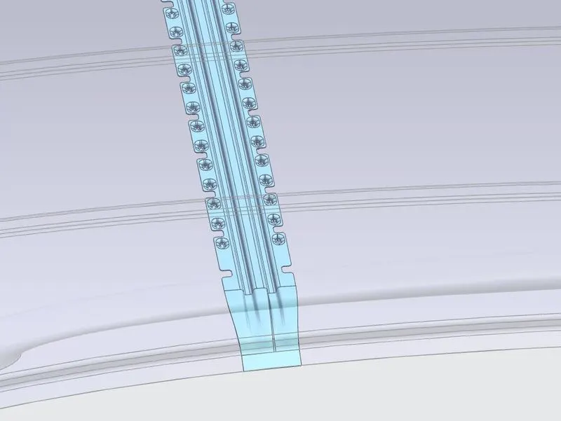
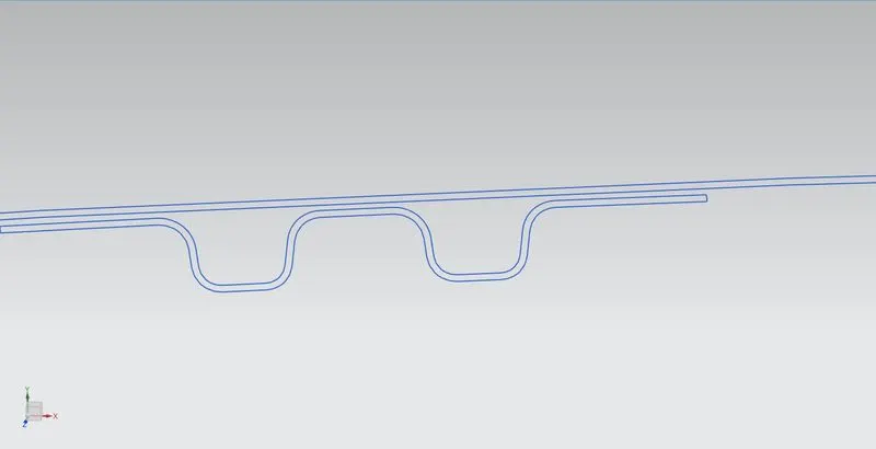
- The bow roof, which is placed under the roof to provide strength to the roof. The number of Bow roofs placed depends upon the length of the car. which is used to make attached to the roof with mastic seals. This mastic seal influences over 60 to 80mm around it. Bow roof can be placed by two methods. One method of placing bow roof between the front and rear roof rail and reinforcement center or it is placed on most flatten surface in the roof. This flattened surface can be found by two methods depends on heat and snow condition
Bow Roof 2:
Rear roof rail
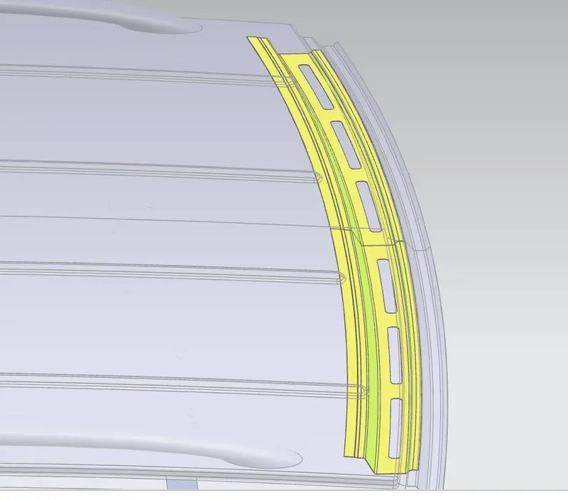
- It is also an additional reinforcement part, which is placed at the rear end of the roof. While designing this part we have to consider rear headroom clearance and rear visibility criteria. Rear headroom clearance is a minimum of 80mm, which depends on the car to car and region to the region.
Cente Roof Rail(Reinforcement):
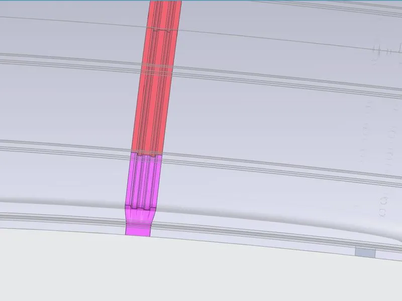
- The reinforcement center is used as a cross-link between bodyside LH & RH respectively. In some cases, the reinforcement center is not joined with the roof and in some other cases, it is made to join in both roof and bodyside. The reinforcement center and BOW roof are joined with either spot weld or mastic sealants.
Heat Distortion Curvature study:
- The heat distortion study plays an important role in sheet metal usage. Heat distortion is a temperature limit above which the material cannot be used for structural applications. This study is used to predict the heat distortion temperature at where the material starts to soften when exposed to a fixed load at elevated temperature. In order to avoid bending/damages on the roof, based on heat distortion temperature. the study helps in positioning of BowRoofs
Bow–roof prediction Formula
W = [1.73 x 10^(-3) x L] + [1.85 x 10^(-8) x (R^2)/t] + [ 1.10x10^(-3) x l] - 2.68
Judgement Condition : OK< 2.7> 3.1
Where
L = Roof Length in X-Direction[mm](Roof dimension in 0-Y)
R = Roof curvature
R = 2(Rx*Ry)/(Rx+Ry)
Rx = X curvature
Ry = Y curvature
t = Roof plate thickness [mm]
l = Bow Roof Span [mm]

SNOW LOAD CRITERIA:
- This evaluation is performed in cold regions where snow occurs. roof design must pass through these calculations to ensure that it has sufficient stiffness to withstand the load due to the accumulation of snow over the roof
Snow load Prediction formula
Qr = [Iy x t2] / [α x s x [(Rx + Ry)/2]2 x 10-8]
Where
α = My x Lx2 x 10-12 , My = Y(Ly-Y)
Judgement condition = Qr ≥ 3.1
250 ≤ s ≤ 380
t = Roof plate thickness [mm]
Ly = Distance between the front and rear roof Rails on the Vehicle along with 0Y[mm]
Length of Roof panel with the center point between Roof rail Front /Rear as the front and rear reference point.
Lx = Distance between the Left and Right end of the roof on the Roof BOW [mm]
The width of the roof panel is exposed on the surface.
Y = Distance front Front Roof Rail to Roof BOW[mm]
s = Distance for which Roof BOW bears divided load [mm]
s = L1/2 + L2/2
Iy = Geometrical moment of inertia of Roof BOW (Y cross-section )[mm4]
Rx = Lateral direction curvature radius of roof panel Y cross-section on Roof BOW [mm]
Roof panel curvature Radius of the Length Lx in Front view
Ry = Longitudinal Direction curvature radius of the Roof panel X cross-section on Roof BOW [mm]
Roof panel X curvature radius of length s in Side view

Conclusion:
The section modulus study for the Master sections and creation for the Front roof rail, Rear roof rail, Bow Roof Rail, and Rear Roof Rail, Ditch area, draft analysis is carried out.