Roof challenge
AIM
To design and assemble the car roof with the reinforcements and perform a curvature study of the same roof to depict the heat distortion and snow loading criteria.
INTRODUCTION
What is roof?
An Automobile roof can be defined as the part of an automobile that covers and protects the passengers from sun, wind, rain and other external elements. In earlier days the roof was made up of Vinyl similar to that used in the horse carriages, but in late 1930’s the companies started adopting the roof to be of steel as it provides better strength and aesthetics to the automobile.
Types of Roofs
- Convertible roofs.
- Hard tops
- Sunroofs
- T-tops.
- Targa tops.
- Vinyl roofs.
DESIGN CONSIDERATIONS
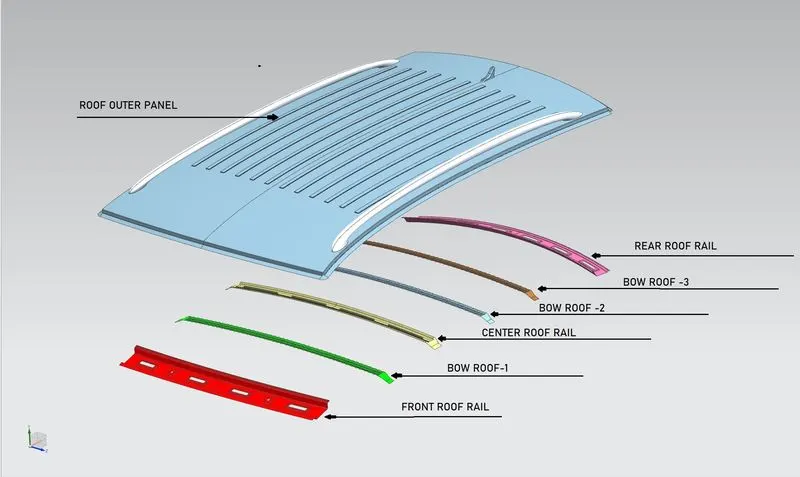
In this project we need to design the front roof rail, rear roof rail along with the roof strengthening components that are bow roof and center roof rail where the styling surface is provided and is used as a reference. The assembly of the roof includes following parts
- Roof Outer Panel
- Front Roof Rail
- Rear Roof Rail
- Center Reinforcement
- 3 Bow Roofs
While designing the reinforcements for the roof there are several design considerations that should be taken into account.
- Material Selection
- Visibility criteria
- Head room Clearance
- Drawability
- Weight and Strength
- Positioning of reinforcements
- Material Selection
Material for every part in the automobile structure plays an important role as it provides the required strength to the structure. The material should be selected keeping in mind the tensile stresses, bending, torsional, static and dynamic loadings. Also, the NVH is a key factor while considerations. Materials used for the components are mentioned below:
- Front Roof Rail: SP783AJQ
- Rear Roof Rail: SP783AJQ
- Center Roof Rail: SP153-980PQ
- Bow Roof: SP121BQ
- Visibility criteria
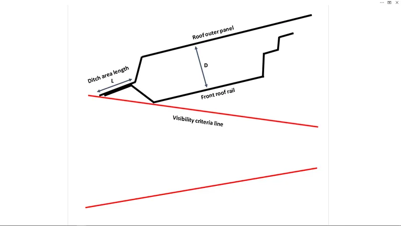
Visibility criteria is one of the most important factors that is considered while designing a roof. The roof should be designed in such a manner that it does not decreases the driver’s visibility of roof.so in order to maintain the visibility the ditch area of the roof should be properly designed and the depth of the roof should be kept within the measurements so as to avoid vision disturbances.
- Head Room Clearance
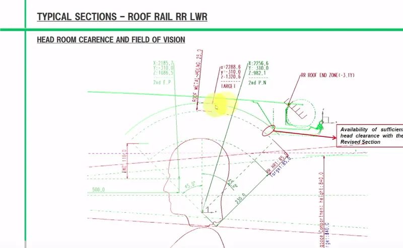
Head room clearance is another factor to be taken into consideration while designing roof reinforcements. The headroom should be perfectly maintained so as to avoid head roof collisions while driving through bumpy tracks and also to get better rear visibility.
- Drawability
The roof structures are manufacture using deep drawing processes therefore it is important to provide a certain positive draft angle for smooth surface build as well as less induced stresses in various parts of the reinforcements.
- Weight & Strength
Another factor to be considered while designing roof structures is weight of the reinforcements and their strengths. The manufacturers these days tend to reduce weight of the vehicle for better performance without impacting the structure strength. So, excess of material is removed and the strength of the structure is improved by embossing.
- Positioning of Reinforcements
The roof reinforcements are positioned basically over two criteria’s
- Heat Distortion Criteria
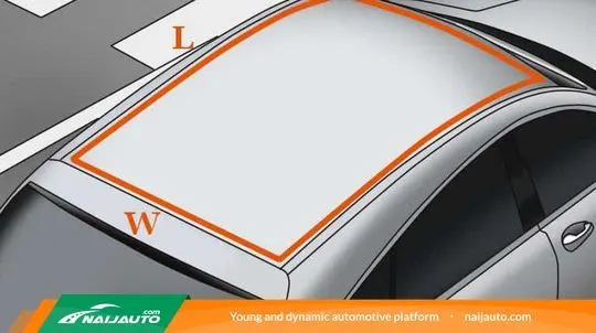
This criterion is used to depict he withstanding temperature of the roof structure. According to this criterion the value of W should be less than 2.7.
- Snow load Criteria
This criterion is used to depict the elasticity of the roof structure. I many areas where there is abundant snowfall huge amount of snow can set up on the roof so this criterion is used so as to depict that after the removal of the snow from the roof the roof should return to its original position. For this the snow load analysis is performed. In this analysis the value of Qr should be greater than 3.1
DESIGN PROCEDURE
PARTS DESIGNED
- Roof Outer Panel
Roof outer panel is the part that is extended from the given styling surface. This part has structures to the front and rear so as to attach the windshield assembly to it. The given below master section was used to design the structure. Also embosses are provided on the roof outer panel structure so as to provide strength.
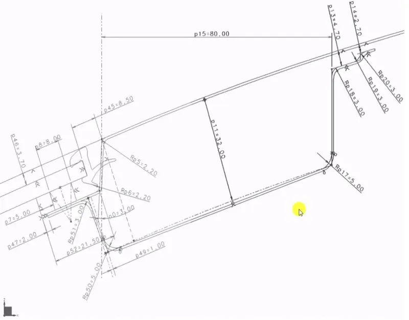
Frontal Master sketch of roof outer panel
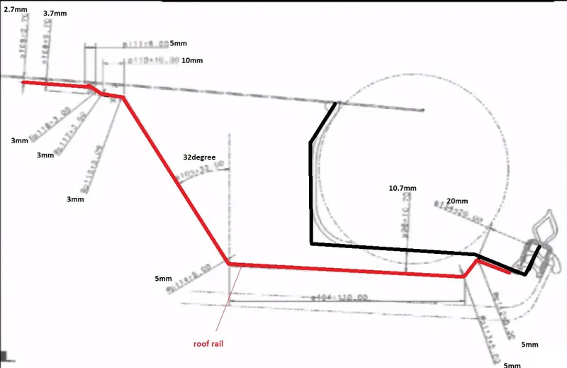
Rear Master Section of Roof Outer panel
From the master section roof outer panel was designed as shown below
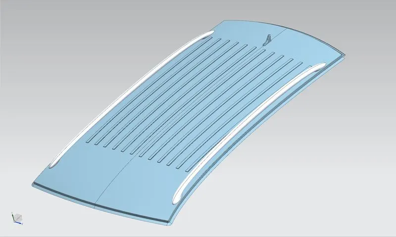
Designed Roof outer panel
Draft analysis was also performed so as to know the feasibility of the structure during manufacturing process.

- Front Roof Rail
Front roof rail is used to provide strength to the roof front and is also used as a link between windshield roof outer and headliner. Same master section was used for the designing of the front roof rail.
Also, Suitable embosses are provided on the front roof rail to provide an extra strength to the structure.
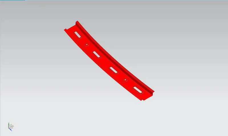
- Center reinforcement
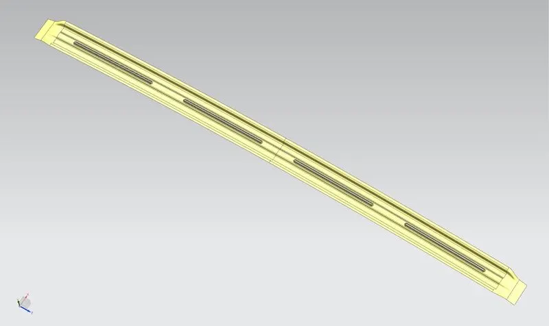
Center reinforcement provides extra strength to the roof during rollovers, so as to avoid physical damage to the passengers. Following master section was used so as to design the center reinforcement. The total length of the center reinforcement was kept to be 60mm.
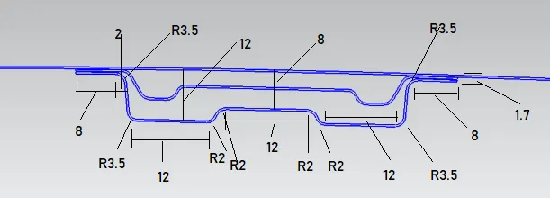
- Bow Roof
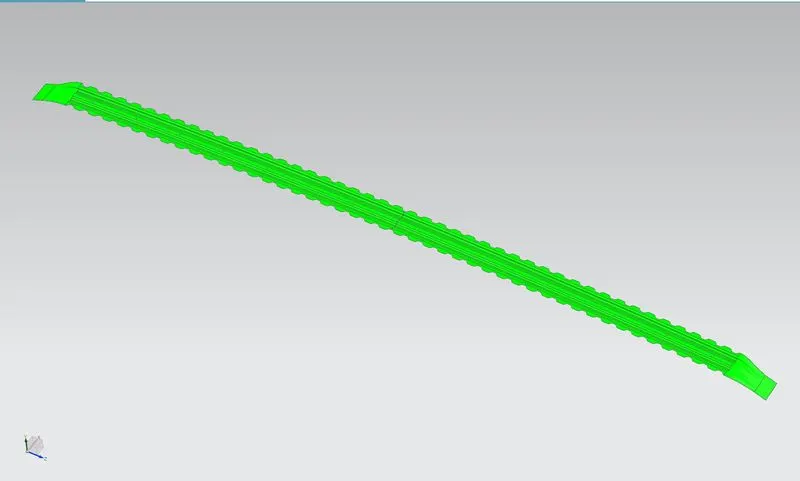
A total of 3 bow roofs are designed using the master section given.
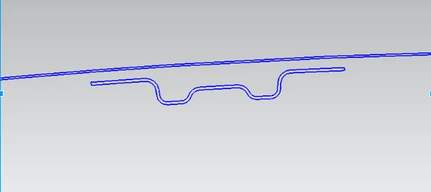
The length of the bow roof was kept to be 42mm.
- Rear Roof rail
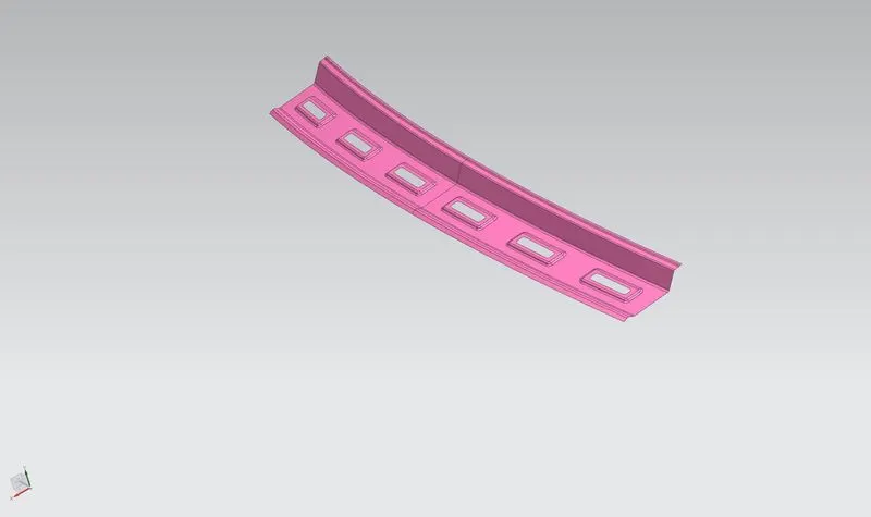
While designing the rear roof rail we have to keep the rear visibility criterion in mind. With the help of given master section following rear roof rail was designed.
Master Section
REINFORCEMENT POSITIONING
After the designing the reinforcement positioning analysis is performed so as to check the heat distortion and snow loading condition effects on the roof.
- Heat Distortion analysis
This analysis is performed on the roof to depict the impact of heat on the roof. This analysis leads to the result that whether the roof can withstand the heat without any deformities. For the roof to pass this analysis the value of W should be less than 2.7
According to the heat distortion criteria
Judgement Condition: OK< 2.7> 3.1
Where,
L = Roof Length in X-Direction[mm](Roof dimension in 0-Y)
R = Roof curvature
Rx = X curvature
Ry = Y curvature
t = Roof plate thickness [mm]
l = Bow Roof Span [mm]
The measured values for the same are shown in the table below

FR: Front roof rail; BR1: Bow roof 1; CR: Centre reinforcement; BR2: Bow roof 2;
BR3: Bow roof 3; RR: Rear roof rail
- Snow load analysis
In many parts of the world the snow fall is high such as Europe. This snow gathers on the roof top, this deforms the roof top. When the snow is removed from the roof top the roof should come back to its original position. So, in order to analyze the strength of the roof for the roof to bear snow load this analysis is done. For the roof to pass this analysis the value of Qr≥3.1.
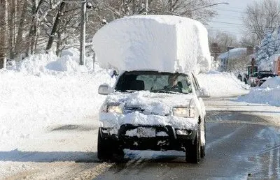
According to snow loading criterion
Qr = [Iy x t2] / [α x s x [(Rx + Ry)/2]2 x 10-8]
Where
α = My x Lx2 x 10-12, My = Y(Ly-Y)
Judgement condition = Qr ≥ 3.1
250 ≤ s ≤ 380
t = Roof plate thickness [mm]
Ly = Distance between the front and rear roof Rails on the Vehicle along with 0Y[mm]
Length of Roof panel with the center point between Roof rail Front /Rear as the front and rear reference point.
Lx = Distance between the Left and Right end of the roof on the Roof BOW [mm]
Width of the roof panel exposed on the surface.
Y = Distance front Roof Rail to Roof BOW [mm]
s = Distance for which Roof BOW bears divided load [mm]
s = L1/2 + L2/2
Iy = Geometrical moment of inertia of Roof BOW (Y cross-section) [mm4]
Rx = Lateral direction curvature radius of roof panel Y cross-section on Roof BOW [mm]
Roof panel curvature Radius of the Length Lx in Front view
Ry = Longitudinal Direction curvature radius of the Roof panel X cross-section on Roof BOW [mm]
Roof panel X curvature radius of length s in Side view.
Given below are the measured values of moment of inertia of various parts
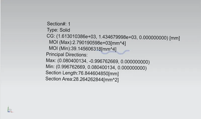
Bow roof 1 Moment of Inertia
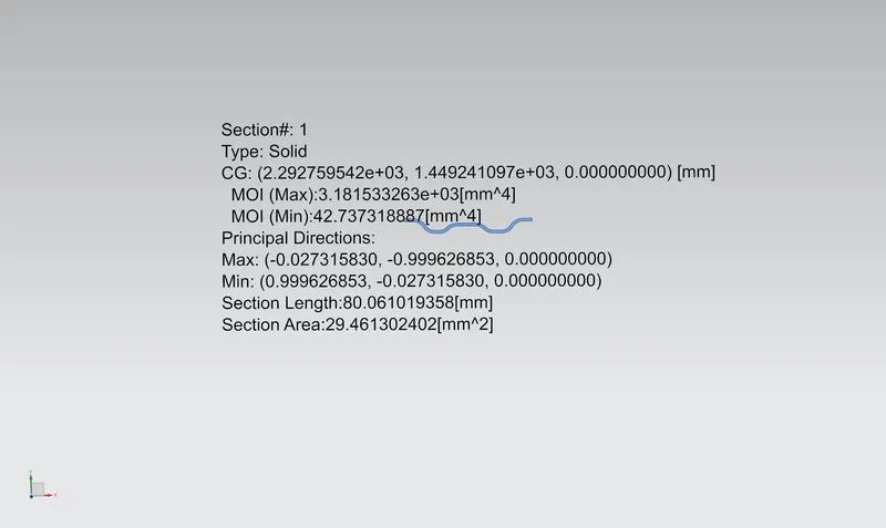
Bow roof 2 Moment of Inertia
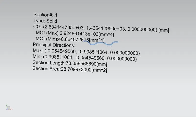
Bow roof 3 Moment of Inertia
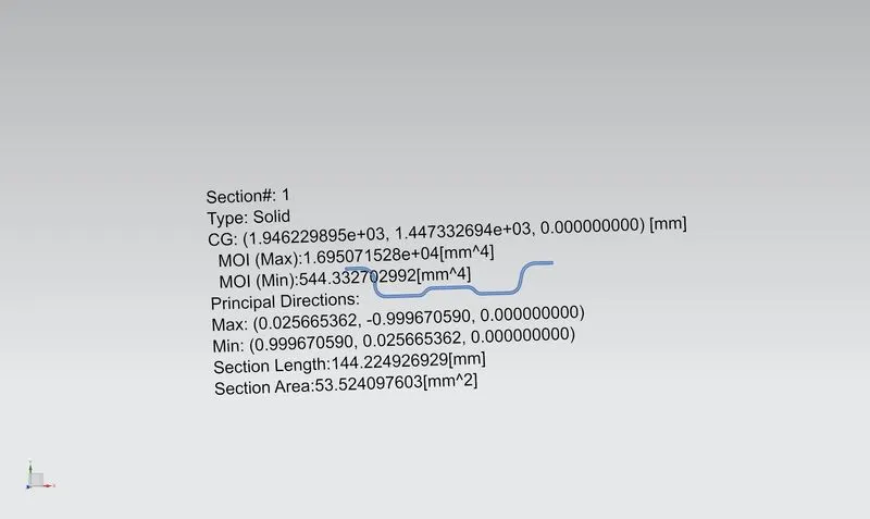
Center Reinforcement Moment of Inertia
The measured values for the analysis are given below

FR: Front roof rail; BR1: Bow roof 1; CR: Centre reinforcement; BR2: Bow roof 2;
BR3: Bow roof 3; RR: Rear roof rail
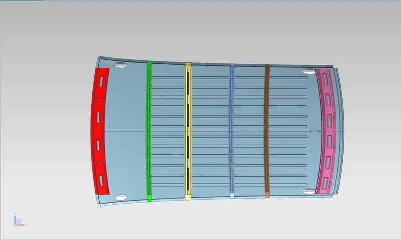
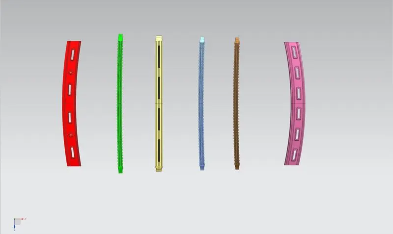
Form the above table it can be predicted that in 3 out of 4 parts the snow load criterion fails. Thus, the roof does not have enough strength to withstand the load of the snow. Thus, repositioning of the reinforcements is required. Since this process is time consuming strength to the roof is added by providing embossed surfaces. Thus, here I have provided embosses over the surface. Also other views of the roof design are also shown below.
CONCLUSION
From the above results it can be concluded that
- The Design of the roof along with reinforcement assembly is complete.
- The roof passes the heat distortion criterion.
- The roof fails in some parts of Snow loading criterion but to overcome that embosses on the surface have been provided