Fender Design Challenge
AIM
To design the Fender Mountings on the drip area, Sill area, Baffle area, and the A-pillar using the given master section.
INTRODUCTION TO FENDER
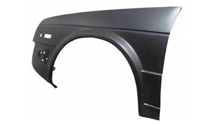
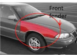
Fender can be defined as a curved portion of the car boy that sits over, he houses of the wheels and covers the side engine view and wheel area.
During the motion of the vehicle the wheels pick up various sand, mud particles as well as stones which can hit different parts in the engine compartment and thus may lead to light or heavy damage to the vehicle. Thus, fender act as a protection to the vehicle parts from such stone and particles. It is also made according to the safety standards for the pedestrians so as to avoid or create minimum injuries during crash.
TYPES OF FENDERS
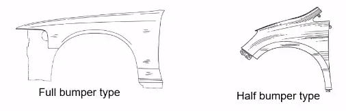
Fenders are mainly of two types
- Full Bumper type Fender
- Half Bumper type Fender
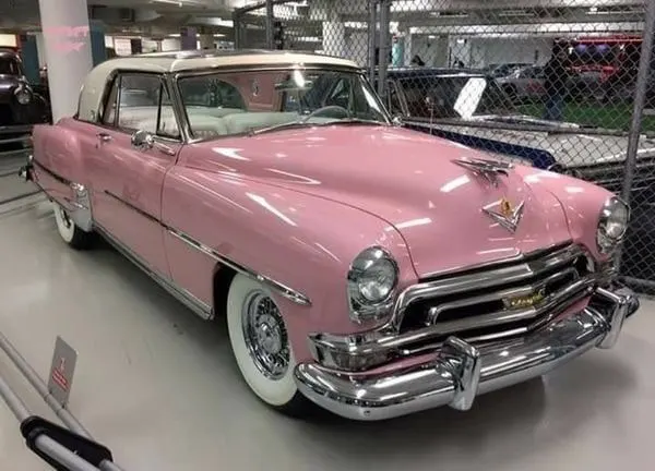
FULL BUMPER TYPE FENDER
These types of fenders are rarely used these days. These fenders were big and required large sheet blanks. They were also costly as the wastage of sheet was more in these types of fenders.
HALF BUMPER TYPE FENDER
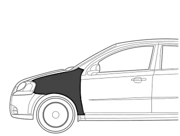
These are the modern-day design considerations for the fender used in the automobiles. These fender designs are cost efficient as very less wastage is produced.
DESIIGN AREAS CONSIDERD WHILE DESIGNING FENDER
- Fender Drip Area: The part that connects the fender to the engine housing area on top.
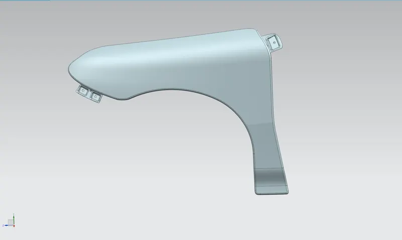
- Bumper mounting area: this mounting is used to join the fender near the bumper area with the fasteners.
- Baffle Area: This is the wheel arc area.
- Sill mountings
- A-pillar Mountings
DRIP AREA
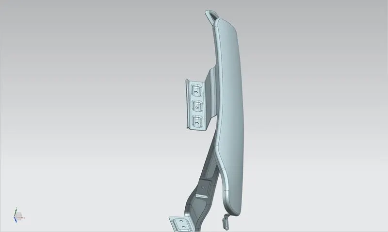
The drip area is attached to the engine compartment through fastners for which holes were provided of 5mm dia and further flat surface of 10mm was kept around for easy fastening. The drip area was designed keeping in mind the master section according to which the distance from the front headlight to the drip area was kept 150mm and from the A-Pillar mounting was to be kept less than 300 mm so it was taken as 150mm. Further the drip area was deigned according to the given master section. The depth for the drip area was also kept below 40mm as increasing the depth above it can cause spring back effect and vibrations as weel as the strength of the drip area could be hindered. Thus the depth was kept close to 36mm.
A-PILLAR MOUNTINGS
For the A-Pillar mounting the sheet was extended using the Law extension command and was extended to a length of 25mm which was trimmed after the completion of the mounting design. For the drip area a new datum plane was made so as to avoid the curved area in the emboss feature.
BUMPER MOUNTING AREA
The bumper mounting area should be a strong area so as to withstand the force of impact during a collision. So, in order to strengthen the design a dart was introduced at an angle of 45 degrees and radius of 5mm at the center of the mounting.
SILL MOUNT
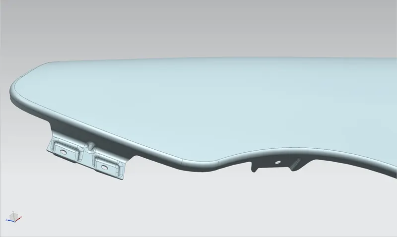
The sill mount is connected near lower part of the front door called the sill area. The embossing in this structure was done towards the inner side so as to minimize the vibrations which can be caused if the embossing was to be done towards the outer side. Thus, keeping the NVH levels in mind the sill mounting was designed.
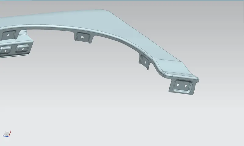
BAFFLE AREA
For the baffle area embossing was done by using new planes to avoid radius of curvature.
Extra Views
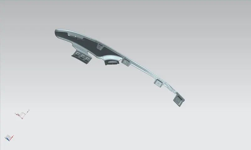
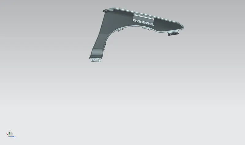
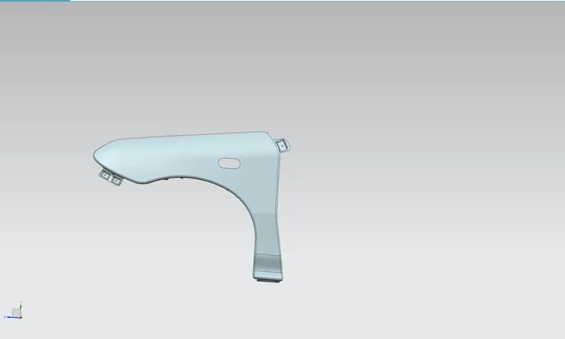
In this view an extra area for indicator is cut out.
CONCLUISON
The fender design is completed by designing the drip, baffle , A-pillar, Sill, and Bumper mounting areas.