Roof challenge
AIM:
To Design a Car Roof and to do the curvature study to resist Heat distortion and Snow Load Condition of the same.
INTRODUCTION :
An automobile roof or car top is the portion of an automobile that sits above the passenger compartment, protecting the vehicle occupants from sun, wind, rain, and other external elements. Because the earliest automobiles were designed in an era of horse-drawn carriage , early automobile roofs used similar materials and designs.
Different types of Car Roofs are :
- Convertible roofs
- Hardtops
- Sunroofs
- T-tops
- Targa tops
- Vinyl roofs
The roof of the cars is made up of multiple parts that provide support and strength to the roof components. The actual roof sheet and the roof rails in a car the front, the center and the rear, While in additional roof rails are called bow roof rails. The number of bow roof rails depends on the size of the roof. Headroom, visibility criteria, and target region also play a key role in roof design.
Vehicle Roof Structure:
A roof structure for a vehicle body includes a roof opening defined by a pair of spaced apart side rails, each having a flange extending inwardly and being vertically offset below the roof surface, and by front and rear headers, each having a flange defining a window opening. A roof panel assembly includes a roof outer panel and a pair of inverted hat-shaped reinforcement rails which underlie the outer side edges of the roof outer panel and include inwardly and outwardly directed legs abutting the underside of the roof outer panel. The outermost portion of the side edges of the roof outer panel are hem flanged over the outwardly directed flanges of the reinforcement rails so that the roof outer panel and the reinforcement rails define the roof panel assembly. The roof outer panel has fore and aft end flanges which overlie the flanges of the front and rear headers and are spot welded thereto. A bead of adhesive is placed on the inwardly extending flanges of the side rails and the roof panel assembly is lowered into the roof opening with the base wall of the reinforcement rails pressed onto the adhesive to attach the roof panel assembly to the vehicle body. The subsequent installation of the front and rear windows hides the spot welds.
Different components of Car Roof :
- Roof
- Front Roof Rail
- Center Roof Rail
- Rear Roof Rail
- Bow Roof 1
- Bow Roof 2
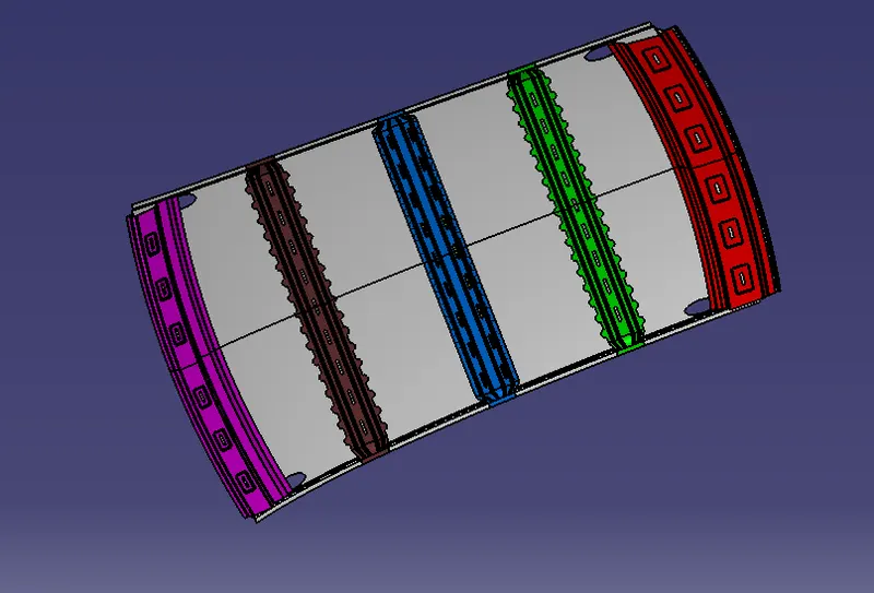
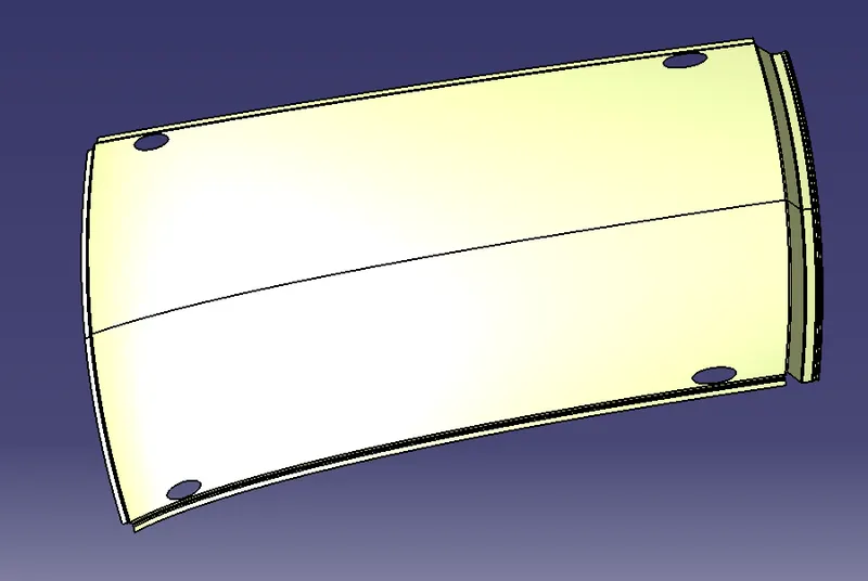
ROOF:
An automobile roof or car top is the portion of an automobile that sits above the passenger compartment, protecting the vehicle occupants from sun, wind, rain, and other external elements. Because the earliest automobiles were designed in an era of horse-drawn carriages, early automobile roofs used similar materials and designs.
FRONT ROOF RAIL :
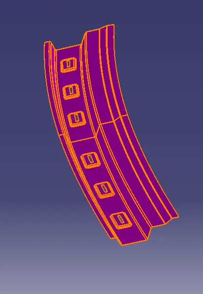
Front roof rails are used in the assembly of a roof in which it provide mounting provisions to windshield glasses and the changes in the front roof rail influences the frontal visibility of the passenger. The major design factor considered is the headroom clearance. The front roof rail also provides provision for the mounting the inside rear view mirror.
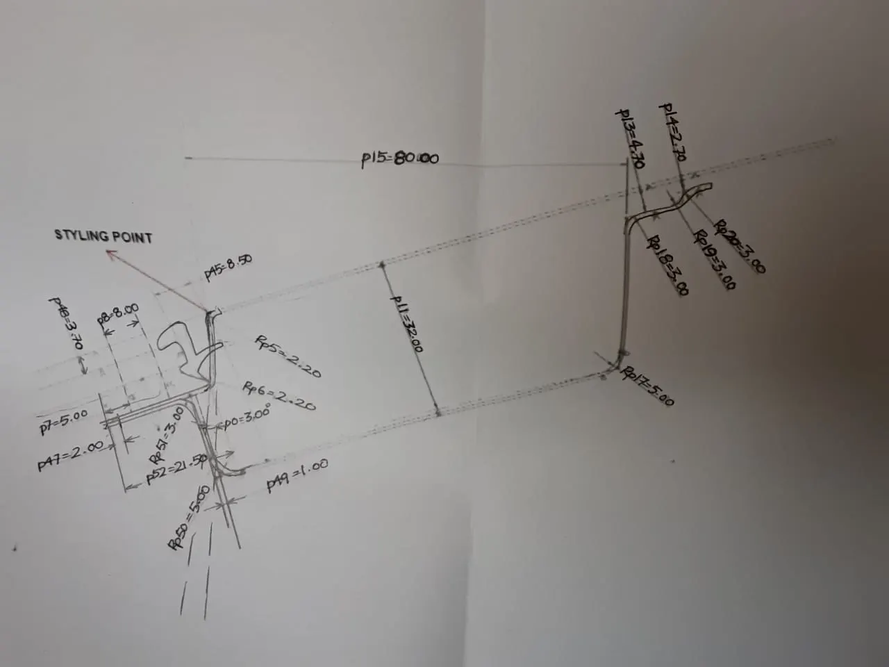
Master section of front roof rail
REAR ROOF RAIL:
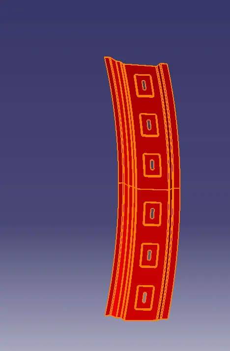
The rear roof rail is the one of the important components of roof assembly which is used for the back door mounting. Similarly to front roof rail important design consideration includes rear passenger head clearance rear visibility of the vehicle.
Master section of rear roof rail
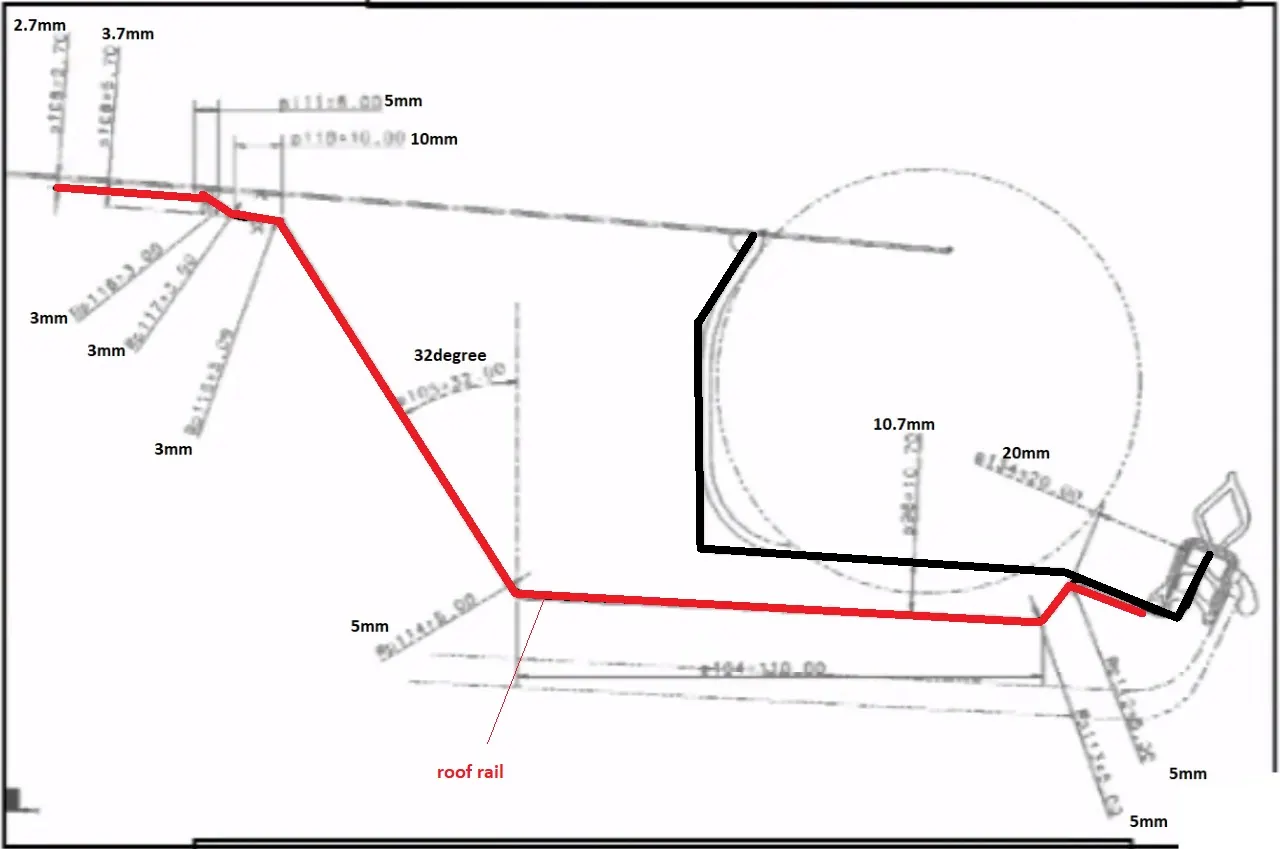
CENTER ROOF RAIL (REINFORCEMENT CENTER):
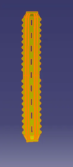
The reinforcement center is used as a cross member between bodyside LH and RH respectively. In some cases, the reinforcement center is not joined with the roof in both roof and bodyside. The reinforcement center and bow roof are joined either spot weld or by mastic sealants and provision for the same are given.
Master section of reinforcement center:
BOW ROOF:
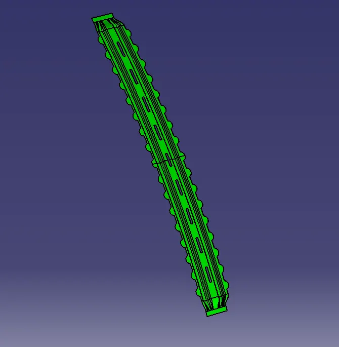
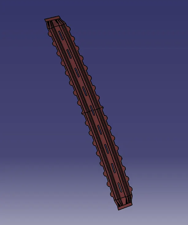
It is an additional stiffening member used in the roof assembly for the localized strength improvements and it is joined directly to roof itself with several spot welding or even with the mastic sealant.
Master section of Bow Roof:
Draft Analysis:
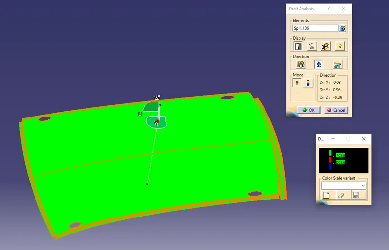
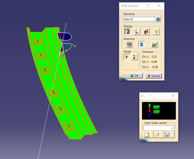
Parts cannot be ejected from the tool if it is at 90- degree for this reason, a small draft is to be provided for each surface for the components in order to easily remove the components from the mould without any defects. Draft is the angle in which the part is tapered to allow it to release. Most of the sheet metal part require minimum 7 degree to 10 degree however 7 degree is widely accepted in sheet metal components design.
ROOF
FRONT ROOF RAIL
REAR ROOF RAIL
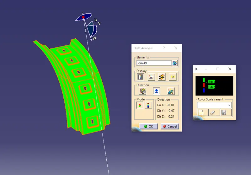
CENTRE ROOF RAIL
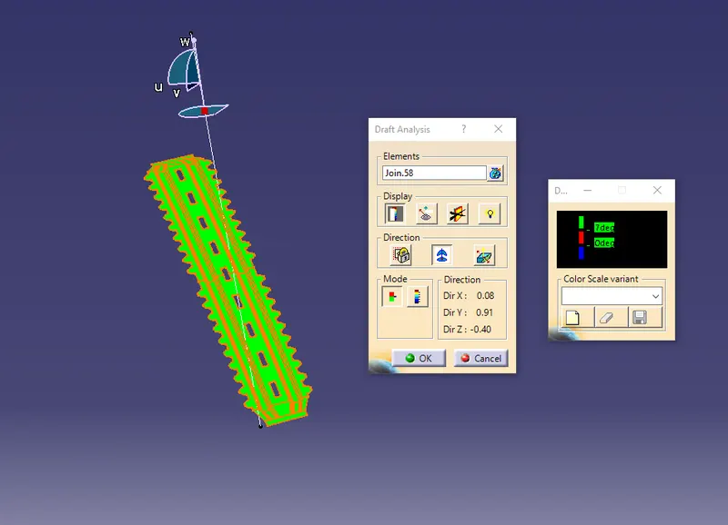
BOW ROOF 1
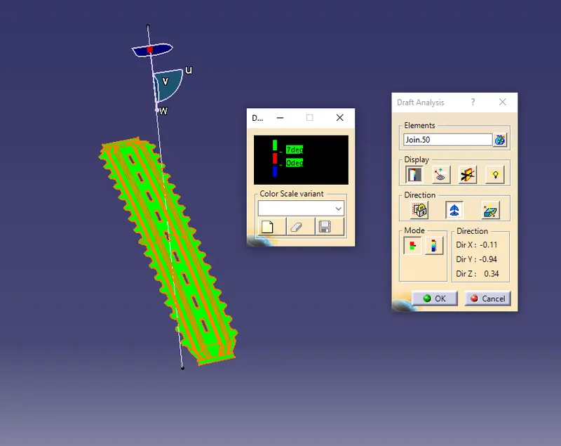
BOW ROOF 2
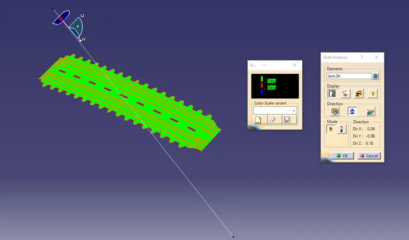
Section modulus calculation:
Section modulus is a geometric property for a given cross-section used in the design of beams or flexural members. Other geometric properties used in design include area for tension and shear, radius of gyration for compression, and moment of inertia and polar moment of inertia for stiffness. Any relationship between these properties is highly dependent on the shape in question.
Formula to calculate section modulus:
S=I/Y
where,
S - Section modulus
Y - Moment of inertia
I - Maximum distance between neutral axis and one of the extreem end of the object
Central Roof Rail & Bow roof :
I = 2.582e-008 m^4 = 25820 mm^4
Y = 79.936 mm
S = 25820/79.936 = 323.008 mm^3
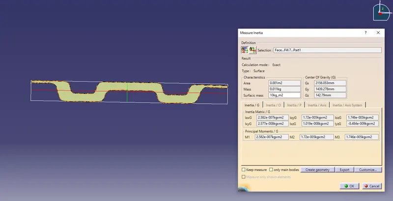
I = 2.582e-008 m^4 = 25820 mm^4
Y = 79.936 mm
S = 25820/79.936 = 323.008 mm^3
Bow Roof 1:
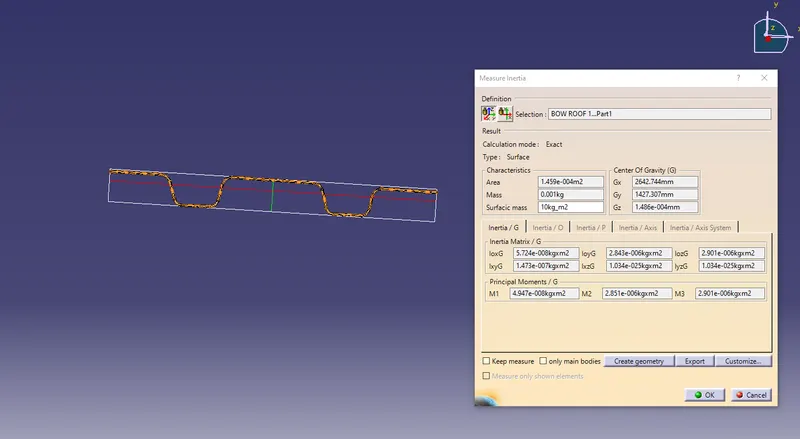
I = 4.947e-009 m^4 = 49470 mm^4
Y = 78.853 mm
S = 49470/78.853 = 627.3699 mm^3
Bow Roof 2:
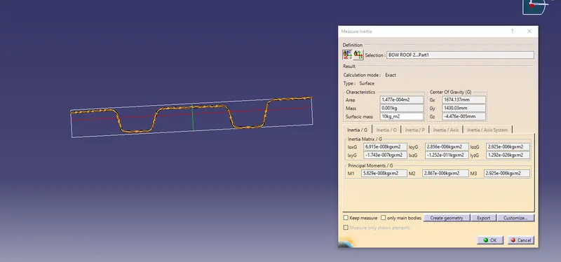
I = 5.829e-009 m^4 = 58290 mm^4
Y = 78.433 mm
S = 58290/78.433 = 743.182 mm^3
HEAT DISTORTION CRITERIA:
Heat distortion temperature is the temperature at which the metal softens and deforms under a specific load. This study is done to check the ability of the roof to withstand high temperature with respect to the positioning of the reinforcements which contribute to increased strength.
Formula to calculate Heat Distortion,
W = [1.73 x 10^(-3) x L] + [1.85 x 10^(-8) x (R^2)/t] + [ 1.10x10^(-3) x l] - 2.68
Judgement Condition : OK< 2.7> 3.1
Where
L = Roof Length in X-Direction[mm](Roof dimension in 0-Y)
R = Roof curvature
R = 2(Rx*Ry)/(Rx+Ry)
Rx = X curvature
Ry = Y curvature
t = Roof plate thickness [mm]
l = Bow Roof Span [mm]
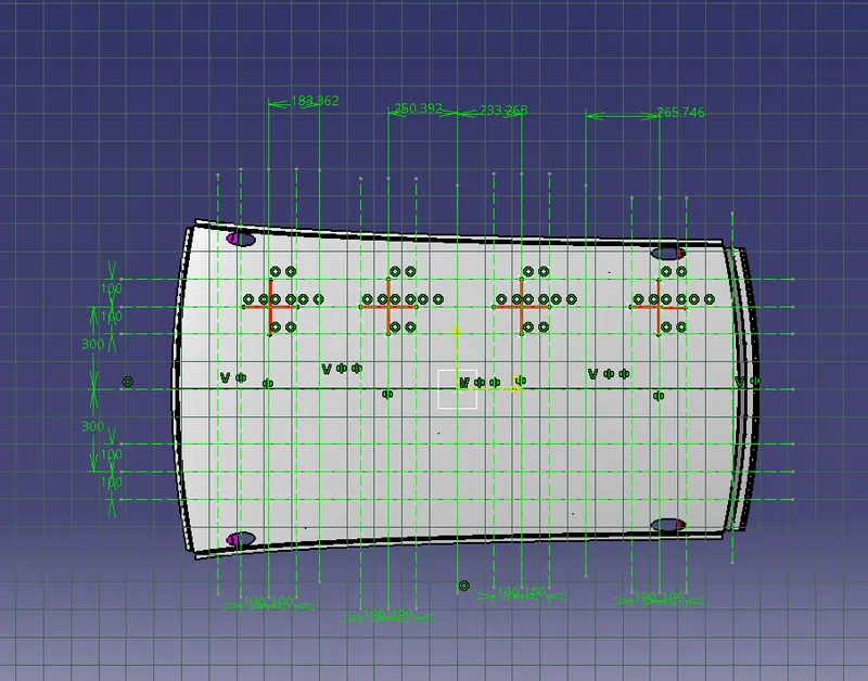
Heat distortion criteria:
| SL NO | BOW's | Rx(mm) | Ry(mm) | R(mm) | I (mm) | L (mm) | t(mm) | (R^2)/t(mm) | W(mm) | Status |
| 1 | FR & 1st | 5756.985 | 2887.194 | 3845.716 | 286.02 | 2031.17 | 0.75 | 19719375.40 | 1.494 | OK |
| 2 | 1st & CRR | 4961.445 | 6257.613 | 5534.654 | 326.40 | 2031.17 | 0.75 | 40843193.19 | 1.944 | OK |
| 3 | CRR & 2nd | 4027.277 | 10397.756 | 5805.824 | 326.84 | 2031.17 | 0.75 | 44943456.42 | 2.02 | OK |
| 4 | 2nd & RR | 3285.28 | 14800.843 | 5377.040 | 285.67 | 2031.17 | 0.75 | 38550078.88 | 1.857 | OK |
FR - Front Roof Rail
CRR - Central Roof Rail
1st & 2nd - Bow Roof 1 and 2 respectivley
RR - Rear Roof Rail
SNOW LOAD PREDICTION:-
This evaluation performed in cold region where snow occurs. Roof design must pass through these calculations to ensure that it has sufficient stiffness to withstand the load due to accumulation of snow over roof.
Snow load Prediction Formula:
Qr = [Iy x t2] / [α x s x [(Rx + Ry)/2]2 x 10-8]
Note: The Qr value given over here is correct. There was a typo error in the formula given in the video.
Where,
α = My x Lx2 x 10-12 , My = Y(Ly-Y)
Judgement condition = Qr ≥ 3.1
250 ≤ s ≤ 380
t = Roof plate thickness [mm]
Ly = Distance between the front and rear roof Rails on the Vehicle along with 0Y[mm]
Length of Roof panel with the center point between Roof rail Front /Rear as the front and rear reference point.
Lx = Distance between the Left and Right end of the roof on the Roof BOW [mm]
Width of the roof panel exposed on the surface.
Y = Distance front Front Roof Rail to Roof BOW[mm]
s = Distance for which Roof BOW bears divided load [mm]
s = L1/2 + L2/2
Iy = Geometrical moment of inertia of Roof BOW (Y cross-section )[mm4]
Rx = Lateral direction curvature radius of roof panel Y cross-section on Roof BOW [mm]
Roof panel curvature Radius of the Length Lx in Front view
Ry = Longitudinal Direction curvature radius of the Roof panel X cross-section on Roof BOW [mm]
Roof panel X curvature radius of length s in Side view
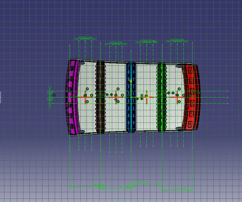
Snow load criteria:
| Sl no | BOW's | t | Lx mm | Ly mm | Y mm | My mm^2 | α mm^4 | s mm | Rx mm | Ry mm | Iy mm^4 | Qr | Status |
| 1 | FR & bow 1 | 0.75 | 1133.136 | 2031.17 | 498.075 | 735940.56 | 0.98 | 491.641 | 4520.322 | 2615.444 | 49470 | 453.72 | OK |
| 2 | bow 1 & CRR | 0.75 | 1081.642 | 2031.17 | 485.212 | 802556.78 | 0.87 | 484.525 | 3771.444 | 6249.602 | 25820 | 137.23 | OK |
| 3 | CRR & bow 2 | 0.75 | 1054.854 | 2031.17 | 483.841 | 760542.95 | 0.83 |
492.056 |
4265.229 | 10954.946 | 58290 | 138.62 | OK |
| 4 | Bow 2 &RR | 0.75 | 1039.924 | 2031.17 | 500.273 | 765869.936 | 0.82 |
#DIV/0! |
2011.132 | 16500.06 | #DIV/0! |
Calculation of α&s factor:
| Sl.no | Lx mm | Ly mm | Y mm | My mm^2 | α mm^4 |
| 1 | 1133.136 | 2031.177 | 498.075 | 763596.292 | 0.98 |
| 2 | 1081.642 | 2031.177 | 485.212 | 750120.769 | 0.87 |
| 3 | 1054.854 | 2031.177 | 483.841 | 748664.597 | 0.83 |
| 4 | 1039.924 | 2031.177 | 500.273 | 765869.936 | 0.82 |
| SL NO | L1 | L2 | s |
| 1 | 498.075 | 485.212 | 491.641 |
| 2 | 485.212 | 483.841 | 484.525 |
| 3 | 483.841 | 500.273 | 492.056 |
| 4 | 500.273 | - | #DIV/0! |
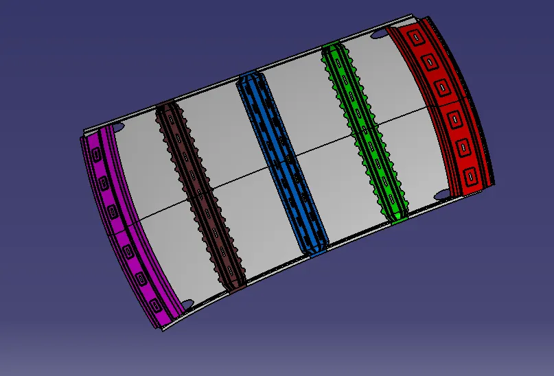
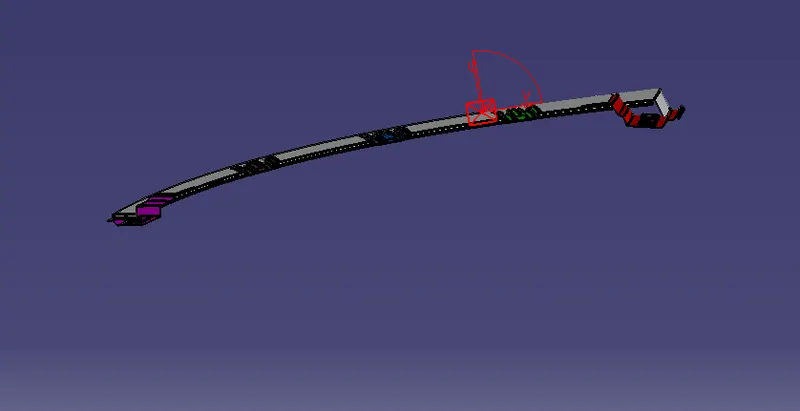
FINAL PRODUCT:-
RESULT:
The car Roof was designed by considering all the design parameters and the curvature study to resist Heat distortion & snow load condition.