Roof challenge
ROOF ASSEMBLY
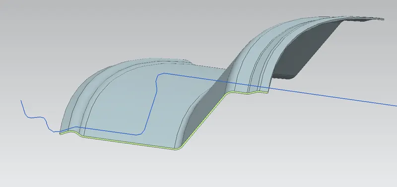
Objective: To develop essential flanges and reinforcements to the roof styling.
To do a curvature study on the roof and perform calculations to determine the position of the bow-roof.
Explanation:
The roof is the top portion of an automobile that protects passengers and the inner parts of the vehicle from sun, wind, water, and other elements.
In order to provide strength to the roof surface, various parts are provided from the inside portion. They are Front Roof rail, Bow roof rail, and rear roof rail. These are all attached to the roof surface through the ditch area which is connected by spot welding. The Ditch area is the extended portion of the roof surface at the edges.
Front Roof Rail: It is a supporting member at the front portion of the roof which is of thickness 0.75mm. The bottom flange mainly depends on the visibility criteria and headroom clearance. One end of the rail is connected to the windshield flange by means of a spot weld and another end is connected to the roof inner surface by mastic sealant.
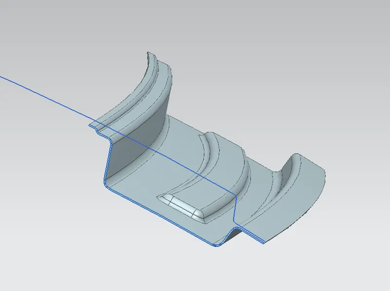
Bow-Roof Rail: It is the portion that provides strength to the roof in any middle portion of the roof surface. As they are completely located on the styling surface of the roof they are attached by means of mastic sealants on both sides. They are given a thickness of 1.25mm in order to get a better Moment of Inertia.
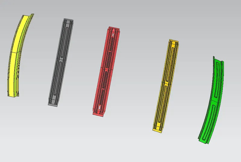
Bow-Roof1 Rail
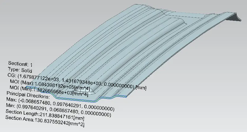
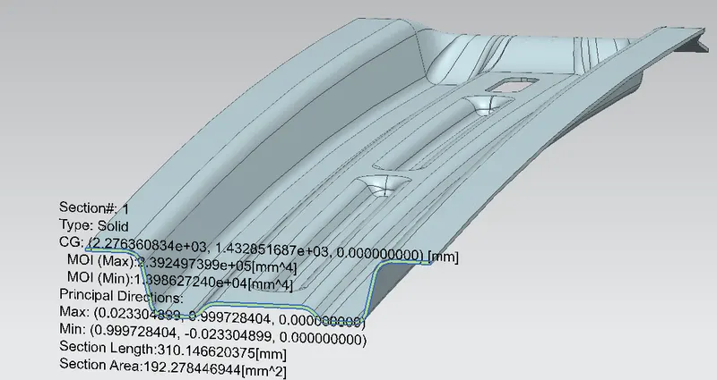
Center-Roof Rail
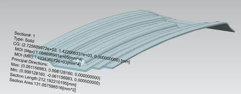
Bow-Roof2 Rail
Rear Roof Rail: It is the supporting member of the roof at the rear side. It is provided with the thickness of 0.75mm. It is also designed based on the rear visibility criteria and headroom clearance. One side is attached to the back door side through spot weld and another portion is connected to the roof inner surface through mastic sealant.
Front Rail, Bow-Rails, and Rear Rail
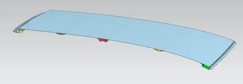
Section View:
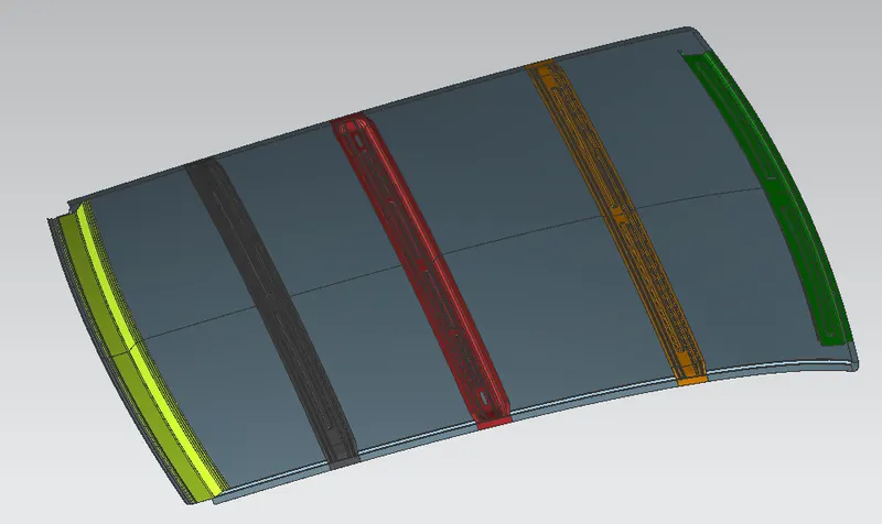
Assembly View:
Curvature Study: It is a study that is done in order to justify the Bow-Roof positioning.
1) Roof Crush Test
2) Heat Distortion Criteria
3) Snowed Criteria
1) Roof Crush Test is done only after manufacturing a physical prototype of the parts and providing suitable loads at specified angles and directions.
2) Heat Distortion Temperature is the temperature at which parts deform under specified load conditions. This criterion test is done in order to check the ability of the roof to withstand the high temperature wrt bow rails positions.
Bow–roof prediction Formula
W = [1.73 x 10^(-3) x L] + [1.85 x 10^(-8) x (R^2)/t] + [ 1.10x10^(-3) x l] - 2.68
Judgement Condition : OK< 2.7> 3.1
Where
L = Roof Length in X-Direction[mm](Roof dimension in 0-Y)
R = Roof curvature
R = 2(Rx*Ry)/(Rx+Ry)
Rx = X curvature
Ry = Y curvature
t = Roof plate thickness [mm]
l = Bow Roof Span [mm]
Analysis Report:
|
Heat Distortion Criteria |
|||||||||
|
Boundary Condition |
Rx |
Ry |
R |
l |
L |
t |
R^2/t |
W |
OK/NG |
|
FR to BR1 |
5739.8968 |
2513.463 |
3496.03 |
398.6994 |
2033 |
0.75 |
16296301.1 |
1.5771 |
OK |
|
BR1 to CR |
4813.2682 |
6836.228 |
5649.1024 |
487.4396 |
2033 |
1.25 |
25529886.3 |
1.8455 |
OK |
|
CR to BR2 |
3834.4447 |
11323.57 |
5728.93 |
339.8166 |
2033 |
1.25 |
26256514.9 |
1.6958 |
OK |
|
BR2 to RR |
3187.106 |
15209.8 |
5269.934 |
342.1852 |
2033 |
1.25 |
22217763.5 |
1.6241 |
OK |
3) Snow load Criteria is the study of the ability of the roof to withstand snowfall and come back to its original shape after deformation.
Snow load Prediction formula
Qr = [Iy x t2] / [α x s x [(Rx + Ry)/2]2 x 10-8]
Note: The Qr value given over here is correct. There was a typo error in the formula given in the video.
Where
α = My x Lx2 x 10-12 , My = Y(Ly-Y)
Judgement condition = Qr ≥ 3.1
250 ≤ s ≤ 380
t = Roof plate thickness [mm]
Ly = Distance between the front and rear roof Rails on the Vehicle along with 0Y[mm]
Length of Roof panel with the center point between Roof rail Front /Rear as the reference point of the front and the rear.
Lx = Distance between the Left and Right end of the roof on the Roof BOW [mm]
Width of the roof panel exposed on the surface.
Y = Distance front Front Roof Rail to Roof BOW[mm]
s = Distance for which Roof BOW bears divided load [mm]
s = L1/2 + L2/2
Iy = Geometrical moment of inertia of Roof BOW (Y cross-section )[mm4]
Rx = Lateral direction curvature radius of roof panel Y cross-section on Roof BOW [mm]
Roof panel curvature Radius of the Length Lx in Front view
Ry = Longitudinal Direction curvature radius of the Roof panel X cross-section on Roof BOW [mm]
Roof panel X curvature radius of length s in Side view
Analysis Report:
|
Snowed Criteria |
||||||||||
|
Boundary Condition |
iy |
α |
Lx |
Ly |
y |
Rx |
Ry |
t |
Qr |
OK/NG |
|
FR to BR1 |
1.382x10^3 |
0.9927 |
1141.253 |
2033 |
495.8677 |
4533.301 |
2596.5754 |
0.75 |
11.28 |
OK |
|
BR1 to CR |
1.3986x10^4 |
1.01 |
1084.8596 |
2033 |
597.3642 |
3808.086 |
6775.9713 |
0.75 |
53.163 |
OK |
|
CR to BR2 |
1.433x10^3 |
0.796 |
1058.388 |
2033 |
449.1934 |
4326.773 |
12006.0527 |
0.75 |
3.39 |
OK |
|
BR2 to RR |
1045.789 |
2033 |
446.4691 |
3841.014 |
17283.2594 |
0.75 |
||||
Conclusion:
Essential flange and reinforcement are provided to the roof styling surface.
A curvature study is done on the roof and the positions of the bow rails are found to be accepted based on the analysis report table.