Roof challenge
Automotive Sheet Metal Design of Roof
Objective
- For the Given Roof styling, Develop the essential flanges and reinforcements, provide appropriate dimension and check for Draft analysis and also submit your section modulus report on the 0-Y section.
- Do a curvature study on the roof and perform calculations to determine the position of the Bow-roof.
Introduction
An automobile roof is the portion of an automobile that sits above the passenger compartment, protecting the vehicle occupants from sun, wind, rain, and other external elements. There are different verities of roofs. Hard top, Convertible, Sunroof, Targa top are the common types of automobile roofs that are seen today.
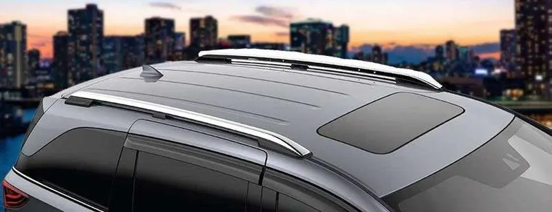
The design of the roof and its strength are crucial in vehicle roll-over accidents. Fortunately, rollover crashes are not that common. But when they do occur the injuries tend to be serious and there are often fatalities. It is the strong A and B pillars help prevent intrusion in these types of crashes and also help hold up the roof. Along with that the roof strength is critical to reducing ejection risk in a rollover. When a weak roof collapses, the supporting pillars deform, warping and shattering the windshield and side windows and sometimes unlatching the doors. This opens many portals for occupant ejection.
How roofs are evaluated:
In the roof strength test (Roof crush test), a metal plate is pushed against 1 side of a roof at a constant speed. To earn a good rating, the roof must withstand a force of 4 times the vehicle's weight before reaching 5 inches of crush. This is called a strength-to-weight ratio. For an acceptable rating, the minimum required strength-to-weight ratio is 3.25. A marginal rating value is 2.5. Anything lower than that is poor.
The ratings depend on vehicle weight, which in turn depends on vehicle options like engine size and 2-wheel vs. 4-wheel drive. The Institute has based its ratings on the typical small SUV, which tends to be 4-wheel drive and comes with a 4-cylinder engine and automatic transmission.
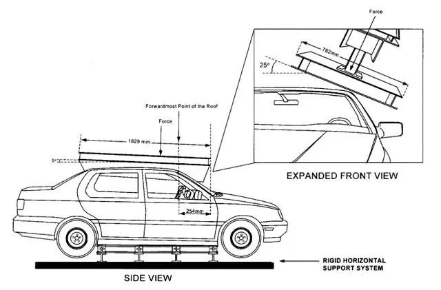
Figure 1: Test device orientation.
Input Elements
- Class A surface of the roof (Skin Data)
- Master section for the Bow roof, Central roof rail, rear and front rails.
- Thickness of the sheet metal = 0.75 mm
Design Process
The design methodology here I have used was Top-down approach. For that in the assembly I have completed the roof outer as the first component. And used its surfaces as reference for the remaining components.
- Roof Outer
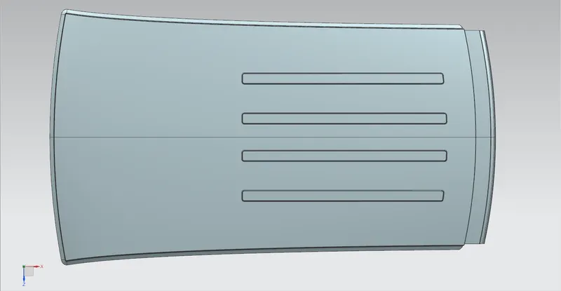
Figure 2: Roof Outer Panel.
From the skin data we can extend the edges in required direction to create the flange. At the rear end the shape of flange depends up on the way how the back door is going to work.
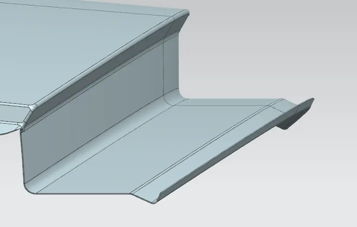
Figure 3: Outer panel flange (rear end).
- Design of Front Roof Rail
The design considerations we should obey while designing front roof rail are,
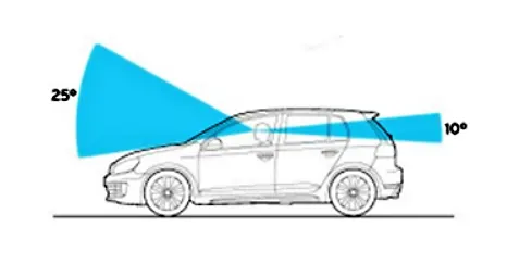
- Visibility Criteria
While increasing the offset distance or the thickness od the front roof rail, we are actually reducing the viewing angle of the driver. So we should be aware of the dimensions that we are providing doesn’t affect the visibility criteria.
- Head room clearance
As like in the visibility criteria if the width and thickness of the front roof rail section is increased, then it reduces the head room clearance.
Draft Analysis
Draft Angle limit = 7 degree
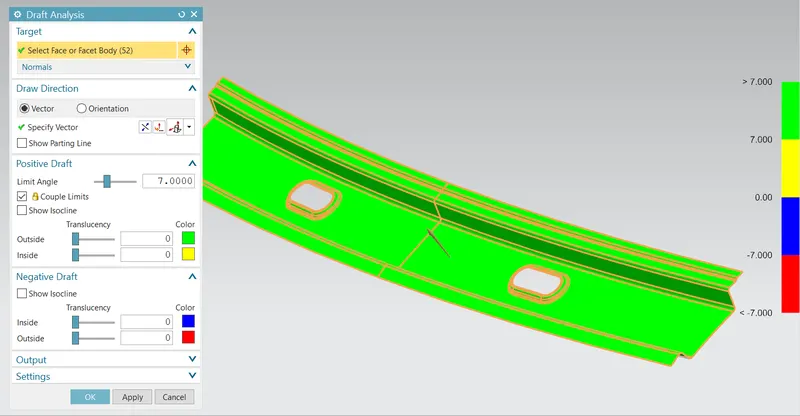
Figure 4: Front roof rail.
- Rear Roof Rail
Rear roof rail is also designed similar to the front roof rail. We should consider the visibility as well as the head room clearance at the rear.
Draft Analysis
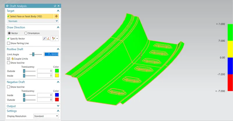
Figure 5: Rear roof rail.
- Central Roof Rail
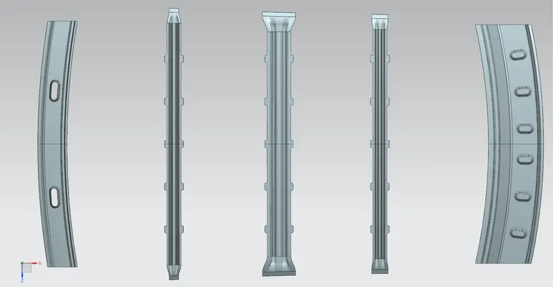
Central roof rails or the reinforcement center are attached almost at the central portion of the roof. The material used for reinforcement center will be always more than the bow roofs. In most cases the brackets for the roof lamp and ac vents are assembled to them.
Draft Analysis
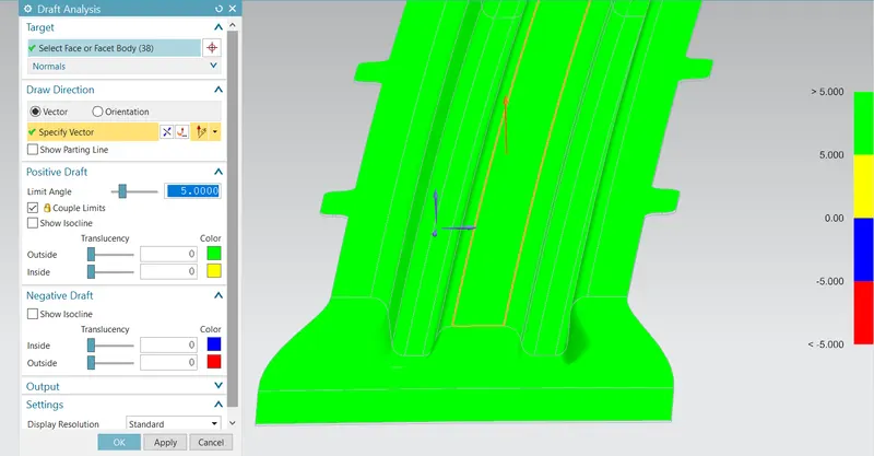
Figure 6: Central roof rail.
Moment of Inertia along 0Y section of Central Roof Rail
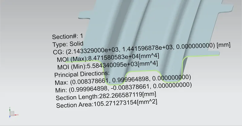
Figure 7: Moment of Inertia along 0Y section of Central Roof Rail.
- Bow Roofs
Bow Roof 1
Draft Analysis
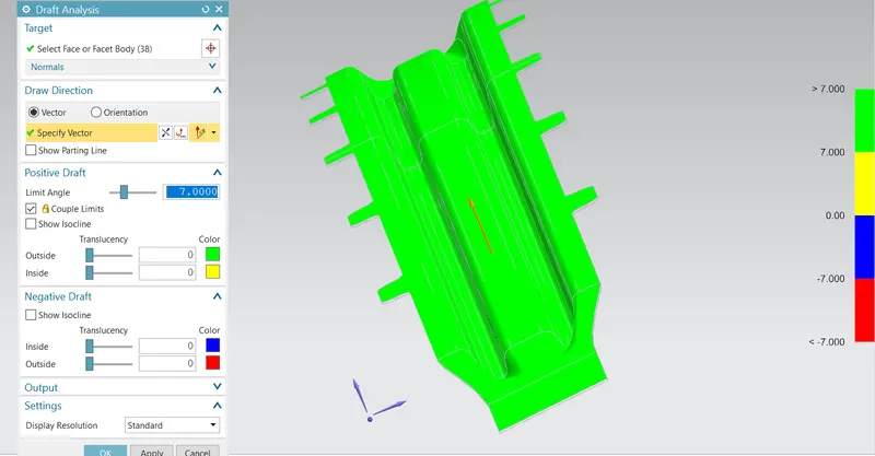
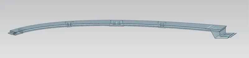
Figure 8: Bow roof 1.
Moment of Inertia of the section along 0Y
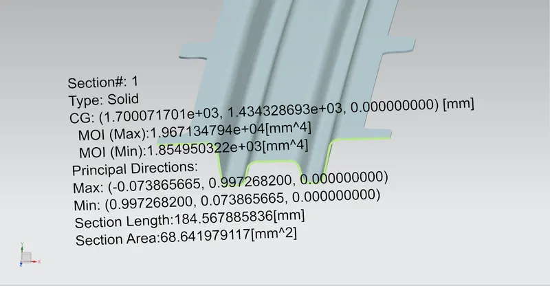
Figure 9: Moment of Inertia along 0Y section of bow roof 1.
Bow Roof 2
Draft Analysis
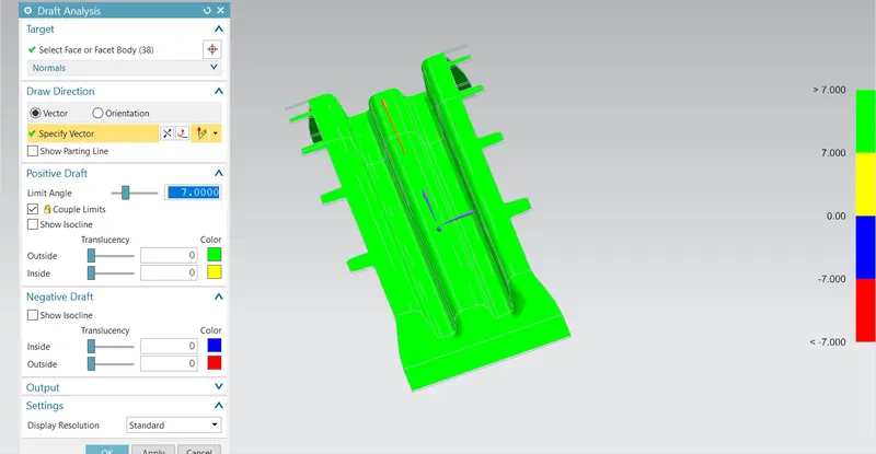
Figure 10: Bow roof 2.
Moment of Inertia of the section along 0Y
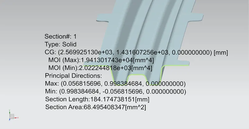
Figure 7: Moment of Inertia along 0Y section of bow roof 2.
Roof Assembly
Components
- Outer Panel
- Front Roof Rail
- Rear Roof Rail
- Central Roof Rail
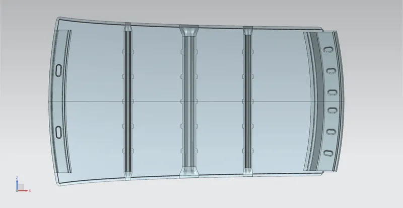
- Bow roof 1
- Bow roof 2
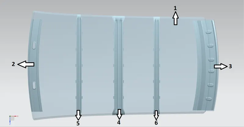
Figure 7: Roof assembly.
Curvature Study
Heat Distortion Criteria
For Heat distortion criteria
Prediction formula,
W = [1.73 x 10^(-3) x L] + [1.85 x 10^(-8) x (R^2)/t] + [ 1.10x10^(-3) x l] - 2.68
Judgement Condition: OK< 2.7< NG
Were,
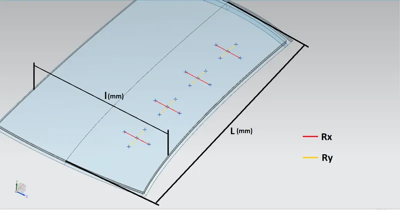
L = Roof Length in X-Direction[mm](Roof dimension in 0-Y)
R = Roof curvature
R = 2(Rx*Ry)/(Rx+Ry)
Rx = X curvature
Ry = Y curvature
t = Roof plate thickness [mm]
l = Bow Roof Span [mm]
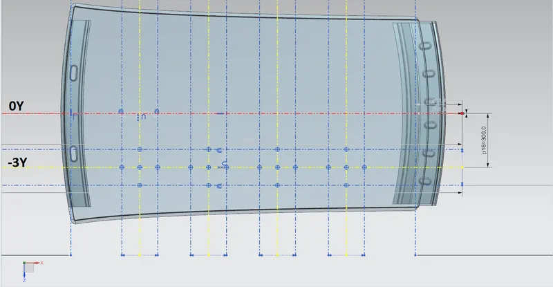
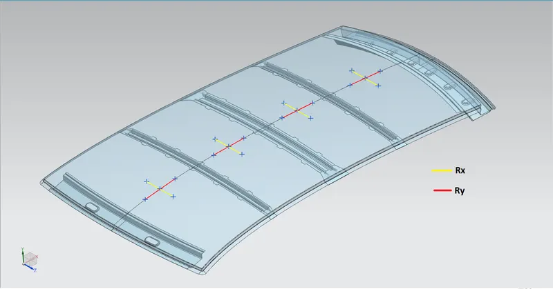
For the curvature study we should find the radius of curvature at four different segments as shown in the picture.
To get those points, first draw an offset of 0Y axis with an offset distance 300mm(-3Y). Also draw perpendicular lines along the plain to divide the outer panel evenly to 4 or 5 parts.
Now offset the 3Y axis and the perpendicular lines symmetrically with 100mm distance. Then project the intersection points to the outer panel and measure the curvature as shown in the figure.
Calculation and Result
|
Heat Distortion Criteria Calculation at -3Y |
||||||||||
|
Position |
L(mm) |
Rx(mm) |
Ry(mm) |
Rx * Ry |
Rx+Ry |
R |
t(mm) |
l(mm) |
W |
Result |
|
FRR- Bow1 |
2024 |
5608.70 |
3497.95 |
19618952 |
9106.65 |
4308.709 |
0.75 |
431.63 |
1.754248995 |
OK |
|
Bow1-CRR |
2024 |
4876.27 |
6583.19 |
32101412 |
11459.46 |
5602.605 |
0.75 |
363.53 |
1.99566941 |
OK |
|
CRR-Bow2 |
2024 |
4124.00 |
9849.64 |
40619915 |
13973.64 |
5813.792 |
0.75 |
346.56 |
2.036473592 |
OK |
|
Bow2-RRR |
2024 |
3504.48 |
13174.39 |
46169386 |
16678.87 |
5536.273 |
0.75 |
428.94 |
2.049395112 |
OK |
Snow Load Criteria
Snow load Prediction formula
Qr = [Iy x t^2] / [α x s ([(Rx + Ry)/2]^2) x 10^(-8)]
Note: The Qr value given over here is correct. There was a typo error in the formula given in the video.
Were,
α = My x Lx^(2) x 10^(-12) , My = Y(Ly-Y)
Judgement condition = Qr ≥ 3.1
t = Roof plate thickness [mm]
Ly = Distance between the front and rear roof Rails on the Vehicle along with 0Y[mm]
Length of Roof panel with the center point between Roof rail Front /Rear as the reference point of the front and the rear.
Lx = Distance between the Left and Right end of the roof on the Roof BOW [mm]
Width of the roof panel exposed on the surface.
Y = Distance Front Roof Rail to Roof BOW[mm]
s = Distance for which Roof BOW bears divided load [mm]
s = L1/2 + L2/2
Iy = Geometrical moment of inertia of Roof BOW (Y cross-section) [mm4]
Rx = Lateral direction curvature radius of roof panel Y cross-section on Roof BOW [mm]
Roof panel curvature Radius of the Length Lx in Front view
Ry = Longitudinal Direction curvature radius of the Roof panel X cross-section on Roof BOW [mm]
Roof panel X curvature radius of length s in Side view
|
Snow load Criteria Condition at 0Y |
||||||||||||||
|
Position |
L1 |
L2 |
Iy |
ɑ |
Lx |
Ly |
y |
My |
S |
Rx |
Ry |
t |
Qr |
Result |
|
FRR- Bow1 |
520 |
475.38 |
1854.95 |
0.927347 |
1110.75 |
1965.46 |
520 |
751639.2 |
238.7839 |
4436.73 |
2740.51 |
0.75 |
36.58919 |
OK |
|
Bow1-CRR |
475.38 |
394.62 |
5584.34 |
0.818957 |
1075.24 |
1965.46 |
475.38 |
708354.2 |
198.5147 |
3768.48 |
6193.38 |
0.75 |
77.87887 |
OK |
|
CRR-Bow2 |
394.62 |
575.46 |
3022.244 |
0.6962 |
1059.77 |
1965.46 |
394.62 |
619884.9 |
288.4157 |
4232.78 |
10550.45 |
0.75 |
15.49602 |
OK |
|
Bow2-RRR |
575.46 |
0 |
1965.46 |
575.46 |
799889.4 |
4128.72 |
15624.06 |
0.75 |
||||||
Sample images
Conclusion
Designed the roof assembly which includes roof outer panel, front roof rail, rear roof rail, central roof rail and bow roofs.
Also did the curvature study of the roof using heat distortion criteria and snow load criteria.
Verified each component using draft analysis.