Roof challenge
AIM
The aim of the project is to create Body in white reinforcements for the roof in order to provide strength to the roof. Draft analysis will be performed on each reinforcement to check if they can be manufactured easily.
Curvature study needs to be done on each reinforcement by performing heat distortion and snowload conditions criteria.
INTRODUCTION
An automobile roof or car top is the portion of an automobile that sits above the passenger compartment, protecting the vehicle occupants from sun, wind, rain, and other external elements.
To provide strength to the ceiling of the car reinforcements are placed below the roof so that it can withstand the damages or loads and does not have impact or minimum impact on the passenger inside the car.
The reinforcements designed in this project for the roof are:
1. Front roof rail
2. Rear roof rail
3. Bow roofs
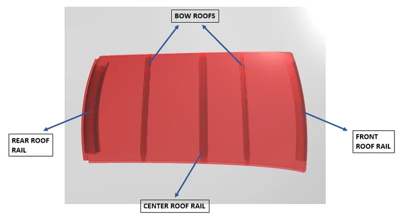
The above image shows the positions of the Front roof rail, bow roofs, centre roof rail and rear roof rail.
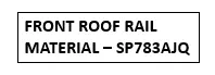
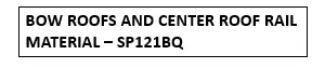
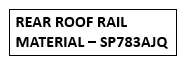
The first step while designing and producing any component is to determine what material should be used to make the component. The below information tells the material that will be used to make the above reinforcements.
There are different types of roofs available on the vehicle.
1. Convertible roofs
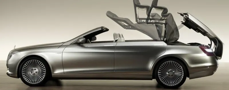
A convertible is a passenger car that can be driven with or without a roof in place. The methods of retracting and storing the roof vary between models. A convertible allows an open-air driving experience, with the ability to provide a roof when required. Potential drawbacks of convertibles are reduced structural rigidity (requiring significant engineering and modification to counteract the effects of removing a car's roof) and cargo space.
The majority of convertible roofs are of a folding construction framework with the actual top made from cloth or other fabric. Other types of convertible roofs include retractable hardtops (often constructed from metal or plastic) and detachable hardtops (where a metal or plastic roof is manually removed and often stored in the trunk).
2. Hadtop
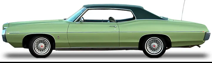
A hardtop is a rigid form of automobile roof, which for modern cars is typically constructed from metal. A hardtop roof can be either fixed (i.e. not removable), detachable for separate storing or retractable within the vehicle itself.
Pillarless hardtop (often referred to as simply "hardtop") is a body style of cars without a B-pillar, which are often styled to give the appearance of a convertible design.
3. Sunroof
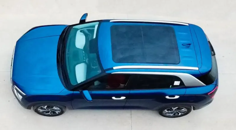
A sunroof is a movable panel that opens to uncover a window in an automobile roof, allowing light and/or fresh air to enter the passenger compartment. Sunroofs can be manually operated or motor driven, and are available in many shapes, sizes and styles. While the term sunroof is now used generically to describe any glass panel in the roof, the term "moonroof" was historically used to describe stationary glass panes rigidly mounted in the roof panel over the passenger compartment. A moonroof has a glass panel that is transparent and usually tinted.
Crash tests performed on the roof of the vehicle
Rollover accidents of a car are the most occurring accidents that we see in our daily lives. The passengers experience major injuries like neck, head and spine injuries. So, to reduce the injuries of a passenger from major fatalities it is important to provide safety in the car. Though safety is provided by seat belts and airbags during accidents, the passenger must have sufficient space for survival in the car during accidents. The roof of the car must have high strength to resist the crush force to avail the passenger some space for survival.
Rollover crashes, especially in the country, are usually very destructive events. Vehicle damage often includes deformation of the roof and its supporting structures. Head and neck injuries are common, and associated with roof deformation. Strengthening of the roof is suggested as an appropriate countermeasure for such injuries.
There are currently no rules covering the strength of the roofs of passenger cars. Similarly, there are no roof crush strength regulations and consideration of such standards appears to be of a low priority. The Department of Transport, through the Federal Office of Road Safety, has requested a review of the costs, benefits and feasibility of introducing a new Design Rule based on the US rule, which is Federal Motor Vehicle Safety Standard 216. This would apply only to passenger cars, and not include convertible models.
Types of Rollovers
Tripped-NHTSA data show that 95% of single-vehicle rollovers are tripped. This happens when a vehicle leaves the roadway and slides sideways, digging its tires into soft soil or striking an object such as a curb or guardrail. The high tripping force applied to the tires in these situations can cause the vehicle to roll over. E.g. Soft soil, Guardrail, Steep Slope.
Un-Tripped -Un-tripped rollovers are less common than tripped rollovers, occurring less than 5% of the time, and mostly to top-heavy vehicles. Instead of an object serving as a tripping mechanism, un-tripped rollovers usually occur during high-speed collision avoidance manoeuvres.
FMVSS 216 Roof crush standards
FMVSS 216, Roof Crush Resistance, establishes strength requirements for the passenger compartment roof of passenger cars, multipurpose passenger vehicles, trucks and buses with a GVWR of 2722 kilograms or less. The purpose of the standard is to reduce deaths and injuries due to the crushing of the roof into the passenger compartment in rollover accidents. The standard does not apply to school buses and passenger cars that conform to the dynamic rollover test requirements of FMVSS 208, Occupant Crash Protection, and S5.3 by means that require no action by passenger car occupants. It also does not apply to convertibles, except for optional compliance with the standard as an alternative to the rollover test requirements in S5.3 of FMVSS.
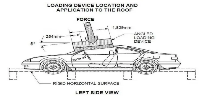
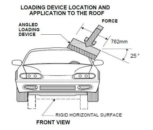
The prescribed static loading device is a rigid unyielding rectangular block 762 millimetres by 1,829 millimetres. It shall not move more than 127 millimetres to achieve the specified resistive load when applied to the forward edge of a vehicle’s roof – see Figures 1 and 2. The resistive load to be achieved is 1½ times the unloaded vehicle weight (UVW) of the test vehicle or 22,240 Newtons, whichever is less.
The force shall be applied in a downward direction perpendicular to the lower surface of the static loading device at a rate of not more than 13 millimetres per second until reaching the compliant resistive load. The test shall be completed within 120 seconds. The static loading device shall be guided throughout the test so that it moves, without rotation, in a straight line with its lower surface oriented as follows.
DESIGN CONSIDERATIONS FOR EACH COMPONENT
In order to design the reinforcements for the roof of the vehicle in this project, a model of the roof is provided as the input so that the reinforcement can be positioned at appropriate position for better strength.
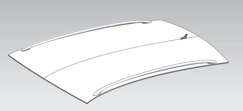
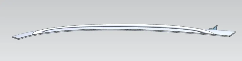
The above image shows the roof model that was provided as the input
The first step in designing the Roof is to design the ditch area for the roof outer panel.

The above image shows the specifications by which the ditch area for the roof outer panel is to be designed.
Steps to design the Ditch Area
1. Extract the outer surface of the unput roof model.
2. With the help of Law extension feature make flanges along the sides of the roof by giving length of the flange and the angle as the input.
3. Giver proper face blends at required places to obtain rounded edges.
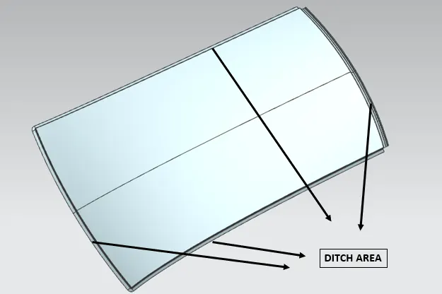
The above image shows the ditch area designed around the edges of the roof.
1. FRONT ROOF RAIL
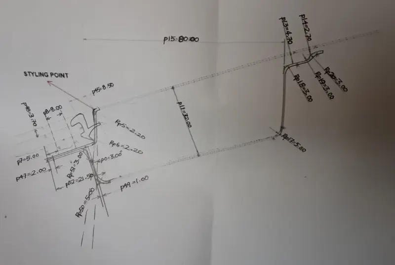
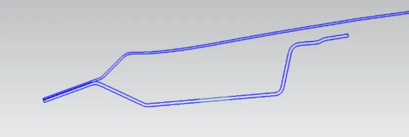
The master section of the front roof rail is provided as input data in order to design the front roof rail in the required shape.
The below image shows the front roof rail master section.
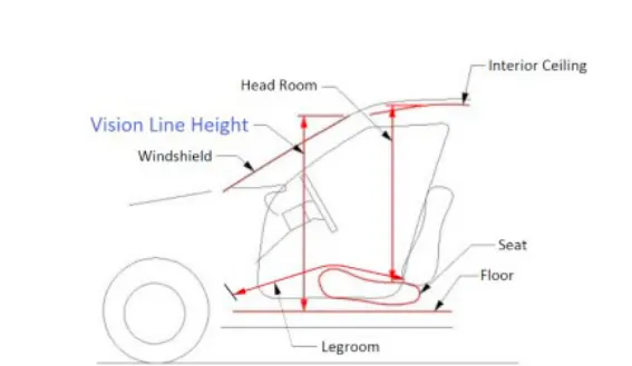
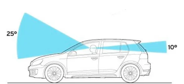
While designing the front roof rail, the most important criteria which needs to be taken care of is that it should not disturb the visibility angle standards for the driver.
The below image shows the various angles that needs to be maintained for the driver.
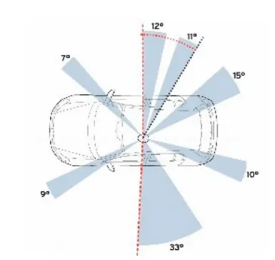
Taking into considerations of all the above factors the Front roof rail should be designed at appropriate position with the desired shape.
Along with this head room clearance gap is also taken into consideration while positioning the front roof rail.
The below images shows the front roof rail designed as per the requirement.
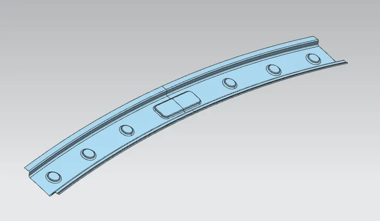
The below image shows the position of the front roof rail under the roof.
Thickness of Front Roof Rail - 1.25 mm.
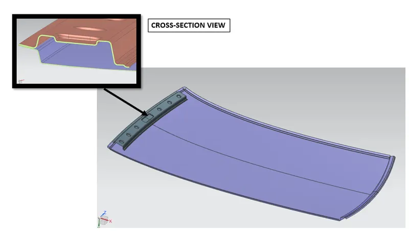
The front roof rail will be attached with the roof with the help of spot welding technique.
Mastic sealents will be applied to the other top portion of the roof rails to attach it firmly with the roof outer panel.
Draft Analysis
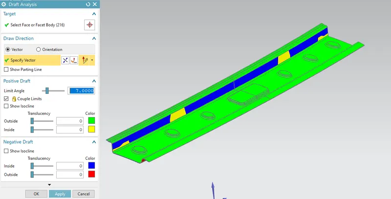
From the above draft analysis we can observe that the front roof rail is clearing in all the portions except for the portion where a 3 degrees draft is give for one flange which was to be made as per the input data. This information will be provided to the styling team to bring this to their notice while further designing the vehicle.
Moment of Inertia for Front roof rail
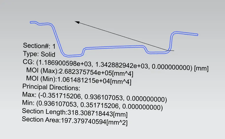
Section modulus of Front Roof Rail
S = MOI(min)/Y
where S = Section Modulus
MOI = Moment of Inertia
Y = distance between the neutral axis and the extreme end of the object
Y = 124.99/2 = 62.495 mm
S(min) = 10614.8/62.495 = 169.850388 mm^3
2. Bow roofs
Bow roofs are the reinforcement that are present below the roof to provide strength to the roof under load and other environmental conditions.
The bow roofs are attached to the roof with the help of mastic sealents and spot welded in the ditch area of the roof to fix it firmly.
How to determine number of bow roofs required for the vehicle?
The number of bow roofs that are required for a vehicle depends upon the size of the vehicle. If the length of the vehicle is more than the roof of the vehicle will also be larger. In order to provide strength to this roof more number of bow roofs will be provided as reinforcement.
If a smaller roof is present for a smaller vehicle then number of bow roofs will be less and in some cases there would be no need for bow roofs as the centre roof rail would be enough to provide sufficient strength to the roof.
How to determine the position of the bow roofs?
The position of the bow roof depends on the curvature of the roof of the vehicle, the roof is stronger where there is more curvature and it becomes weak near the flatter region. From having the look on the input design of the roof we can determine the curvy and flatter regions in the roof. Based on that we can provide more number of bow roofs at the flatter portion to provide strength in that region.
The master section provided as input to design the bow roof is shown below:
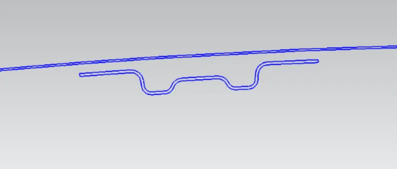
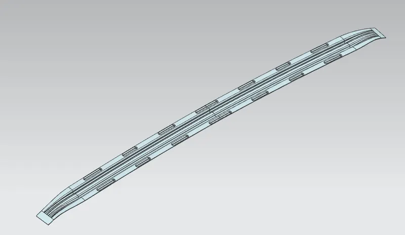
The bow roof designed as per requirement is shown above.
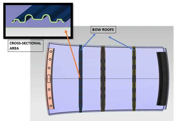
Thickness of Bow roof - 1.25 mm.
Moment of Inertia for Bow roof 1
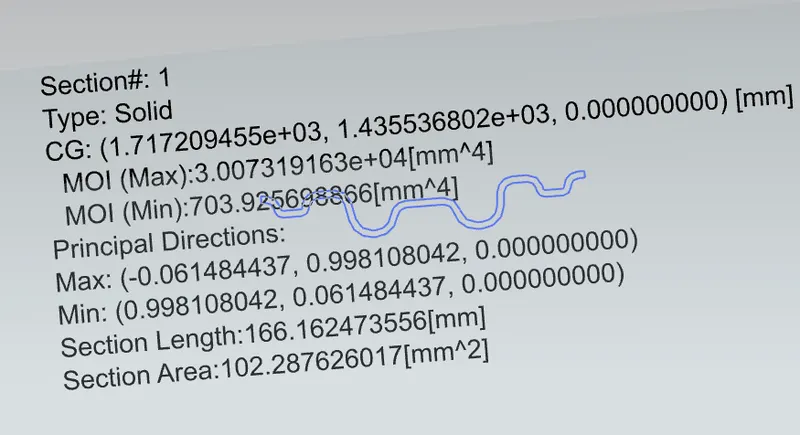
Section modulus of Bow Roof 1
S = MOI(min)/Y
where S = Section Modulus
MOI = Moment of Inertia
Y = distance between the neutral axis and the extreme end of the object
Y = 59.9/2 = 29.95 mm
S(min) = 10614.8/29.95 = 23.50317195 mm^3
Moment of Inertia for Bow Roof 2
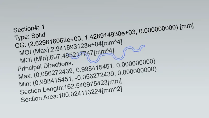
Section modulus of Bow Roof 2
S = MOI(min)/Y
where S = Section Modulus
MOI = Moment of Inertia
Y = distance between the neutral axis and the extreme end of the object
Y = 59.96/2 = 29.98 mm
S(min) = 697.49/29.98 = 23.26517678 mm^3
Draft Analysis
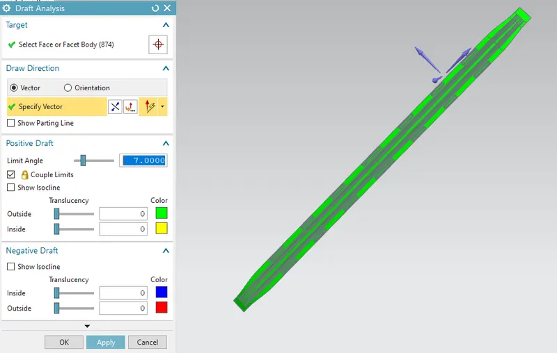
From the above image we can observe that we can easily design the bow roof along the tooling direction as it is clearing in every region.
3. Centre Roof Rail
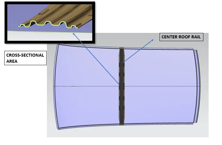
The centre roof rail is present at the centre of the roof, it is also a reinforcement which is placed below the roof to provide strenght to the roof.
Thickness of centre roof rail - 1.25 mm.
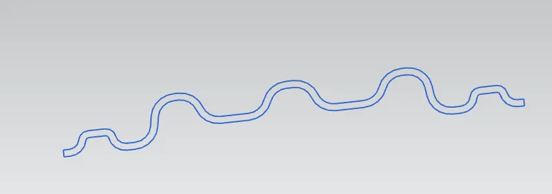
Master section of centre roof rail is shown above
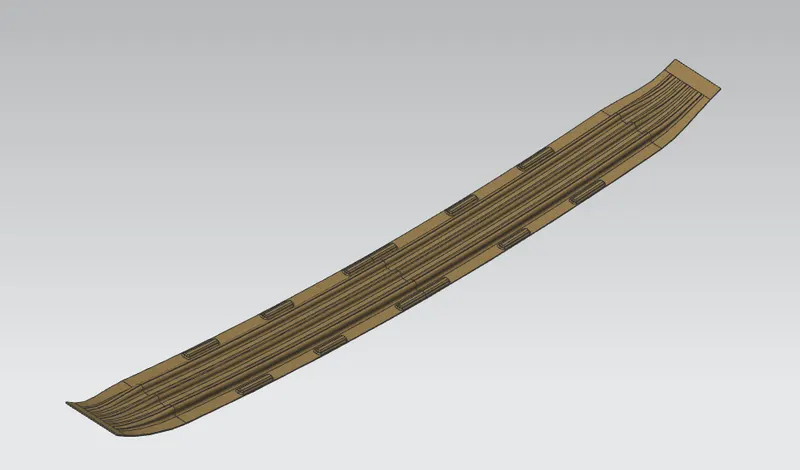
The designed centre roof is shown above
Draft Analysis
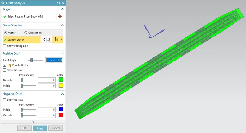
From the above image we can observe that we can easily design the centre roof rail along the tooling direction as it is clearing in every region.
Moment of Inertia for Centre Roof Rail
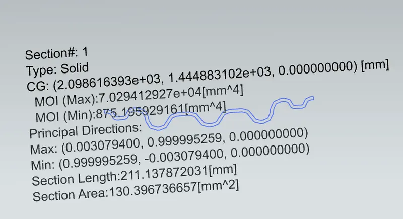
Section modulus of Centre Roof Rail
S = MOI(min)/Y
where S = Section Modulus
MOI = Moment of Inertia
Y = distance between the neutral axis and the extreme end of the object
Y = 79.92/2 = 39.96 mm
S(min) = 875.19/39.96 = 21.90165165 mm^3
4. Rear Roof Rail
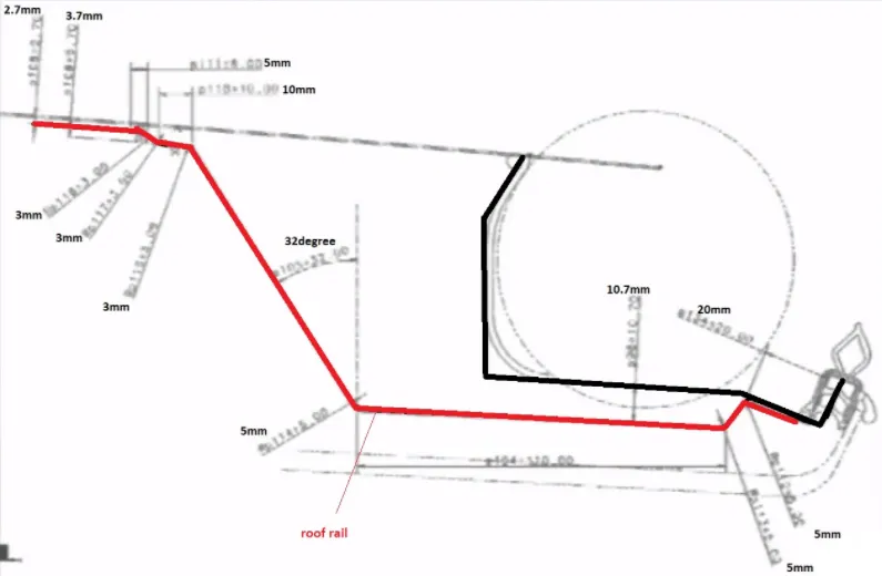
Real Roof rail is present at the back portion of the roof, it will be spot welded with the back door and fixed with the roof with the help of mastic sealents.
Thickness of Rear Roof rail - 1.25 mm
Mastersection provided as input.
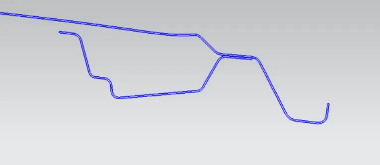
Specifications for the rear roof rail.
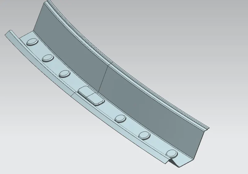
From the above details the rear roof rail is designed as per requirement, which is shown in the below image.
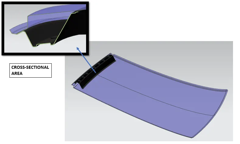
Position of the rear roof rail is shown below:
Draft Analysis
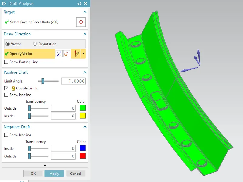
From the above image we can observe that we can easily design the rear roof rail along the tooling direction as it is clearing in every region.
Moment of Inertia for Rear Roof Rail
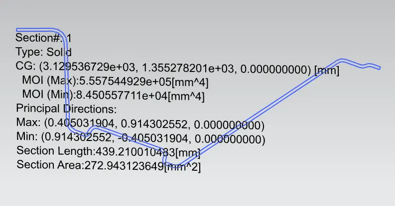
Section modulus of Rear Roof Rail
S = MOI(min)/Y
where S = Section Modulus
MOI = Moment of Inertia
Y = distance between the neutral axis and the extreme end of the object
Y = 155.79/2 = 77.895 mm
S(min) = 84505.57/77.895 = 1084.865139 mm^3
CURVATURE STUDY CLACULATIONS:
In order to determine the position of the bow roofs curvature study needs to be done so that the roof does not when load is applied on it.
For this purpose heat distortion criteria and snowload criteria is calculated below to understand the best positions of the bow roof to provide proper strength to the roof.
Heat distortion Criteria
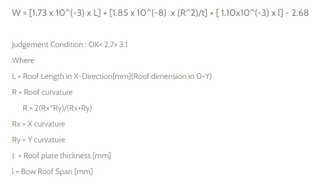
Steps to know the values for the above parameters:
1. First a 0Y line will be created at the centre of the styling of the roof which would be in horizontal direction.
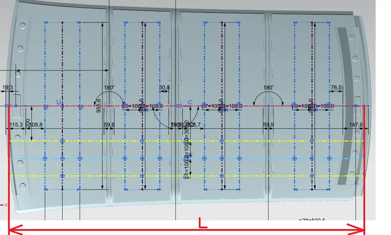
2. Create a middle line between the roof rails and bow roofs and then make an offset of 100 mm with respect to this line in both the directions.
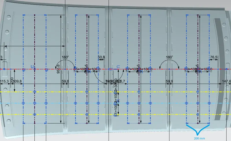
3. An offset of -3Y (i.e. 300 mm) will be made below to the horizontal line.
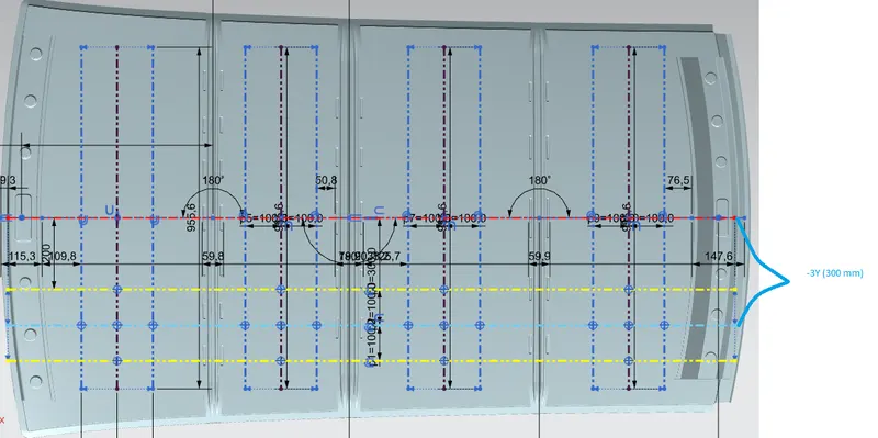
4. Again offset will be made from the above line which would be 100 mm above and below the line.
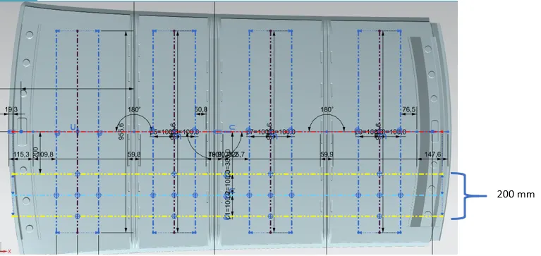
5. 6 Intersection points will be made through the intersection of the lines.
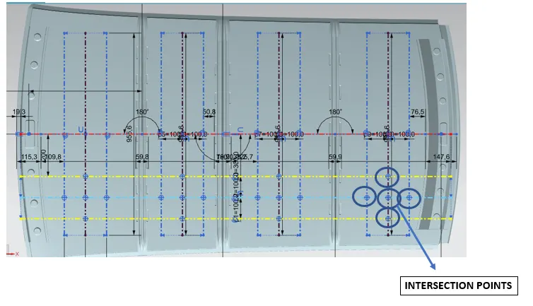
7. These intersection points will be projected on the styling of the roof with the help of the project curve feature.
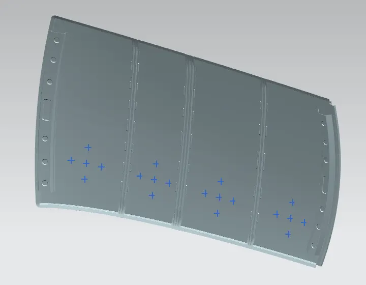
8. Arcs will be made by joining the three lines horizontally and vertically to obtain Rx value along X direction and Ry value along Y direction.
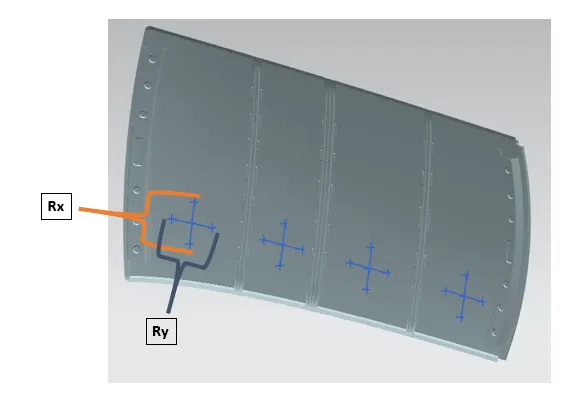
From the above data all the values can be obtained and hence the heat distortion criteria is calculated which is shown below:
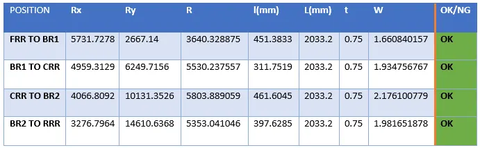
From the above calculations we can conclude that the designed bow roofs and centre roof rail are at appropriate position and can easily withstand heat distortion.
SNOWLOAD CRITERA

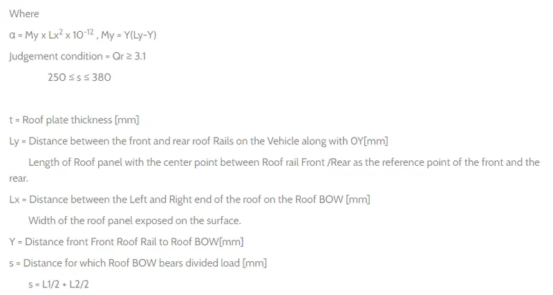
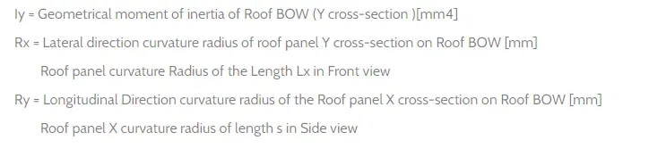
Steps to know the values for the above parameters:
1. The first step is to create the 0Y line considering the styling surface of the roof in the horizontal direction. The length of this line will give Ly value.
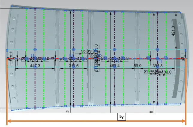
2. Now the Ly line needs to be offseted with a distance of 100 mm in both the direction.
3. Middle line needs to be made between each reinforcements to obtain the Lx value.
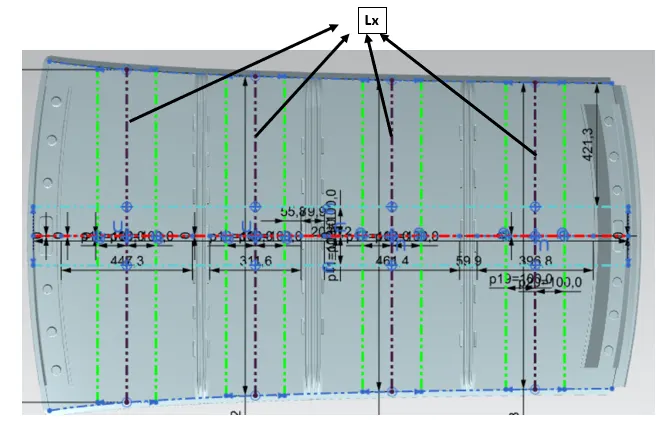
4. With the help of the middle line offset lines are created which will be 100 mm apart in both the sides.
5. Now intersection points will be generated through the intersection of the lines that we created.
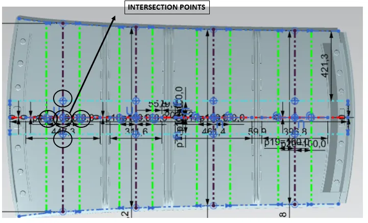
6. Now these points will be projected on the styling of the roof surface.
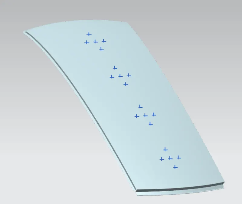
7. Arcs will be drawn by attaching the three points together to obtain the Rx and Ry values.
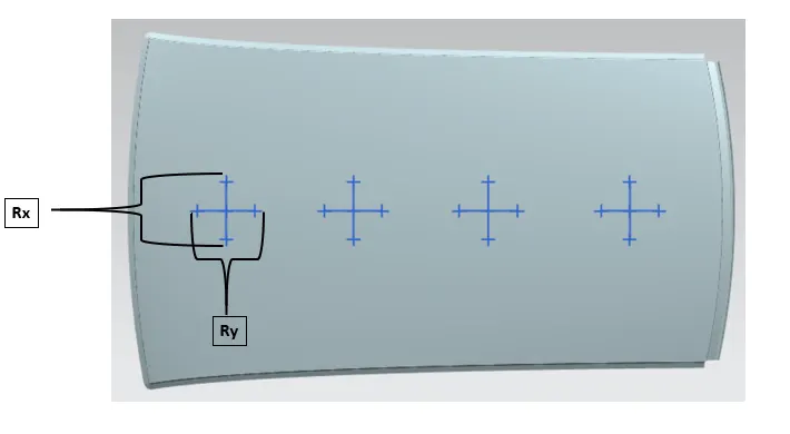
Snowload criteria Calculations:

From the above table we can observe that the snowload condition is not satifying in the region between the center roof rail and the bow roof 2 as the value of Qr should be greater than or equal to 3.1
Solution for above case:
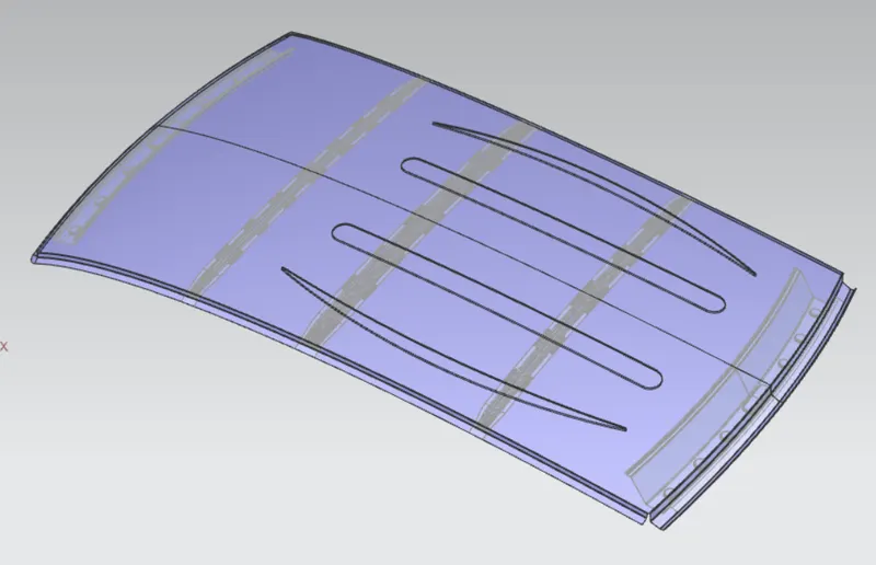
For solving the above problem in the region between Center roof rail and bow roof 2 embosses will be made on the outer roof in order to provide strength to the roof so that the roof can withstand the snowload condition.
The modified roof with embosses is shown below:
DIFFERENT VIEWS OF THE DESIGN
1. Top view
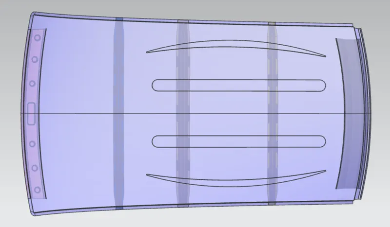
2. Side view
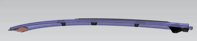
3. Front view
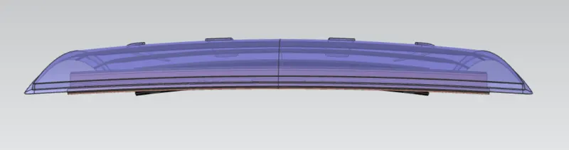
5. Bottom view
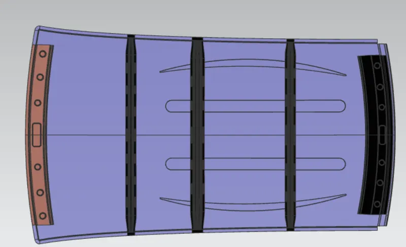
CONCLUSION
1. The roof and the reinforcements were designed as per requirements by placing them at required positions.
2. Ditch Area is designed along the edges of the roof.
3. Draft analysis was performed on each component.
4. Section Modulus is calculated for each reinforcement.
5. Curvature stud of the roof is performed and it was observed that the design passed the heat distortion criteria, but the snowload criteria could not be cleared in the region between center roof rail and bow roof 2.
6. To fix this solution either one of the solution can be performed.
- This will be notified to the styling team to improve the curvature in this region to improve the strength at this place, if this is not accepted by the styling team,
- Embosses on the roof can be designed to improve the strength in this region.