REVIT_Creation of Basic Drawing_Week 2
1) What is BIM? Summarize the features of BIM and benefits of using BIM over 2D CAD tools.
ANS)
BIM stands for Building information modeling. BIM is a process supported by various tools, technologies, and contracts involving the generation and management of digital representations of physical and functional characteristics of places.BIM is used in presenting 3D models.BIM is flexible in usage, in BIM when we make a change in one view all other views automatically change which is not the same as in 2D CAD.
CAD models have only one visual representation: highly detailed.
BIM models are designed for plasticity — they can be zoomed in on and out of, expanded, contracted, and so on.
----------------------------------------------------------------------------------------------------------------------------------
2) Understand the concept of Categories, Families, Elements, Instances in Revit. Go to Insert Tab, choose a category. Pick a family and element. Understand the instances and insert it to Revit model.
ANS)
Aim: To use insert Tab and choose a category, Pick a family and element and Understand the instances and insert it to Revit model.
Tools used:
- insert tab
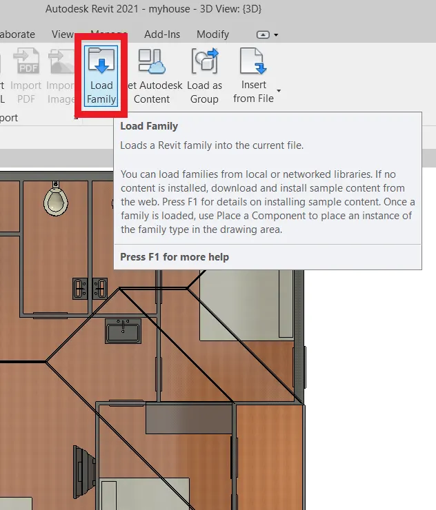
- load family
- component
- property browser
Procedure:
- Go to insert from the toolbar.
- Click on the load family from the import section.
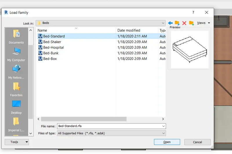
- from the dialog box select the required family to be loaded.
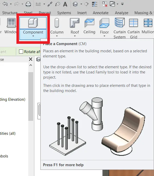
- from the architectural toolbar click the component to use the model elements selected from the insert.
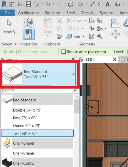
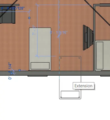
Result: An element was inserted successfully.
----------------------------------------------------------------------------------------------------------------------------------
3) Setting up a Project – Open a project file with architectural template. Save the file with appropriate name. Set up the project units to Imperial / Metric based on your convenience of modelling. Complete the project information under Manage tab. Set up the maximum backups for project file to 3
ANS)
Aim: To open a project file with an architectural template. To save the file with an appropriate name. To set up the project units to Imperial / Metric based on your convenience of modeling and complete the project information under the Manage tab. At last set up the maximum backups for the project file to 3.
Tools Used:
- File
- Manage tab
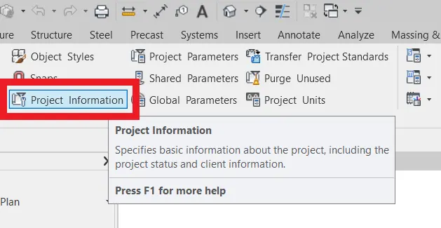
- Project information
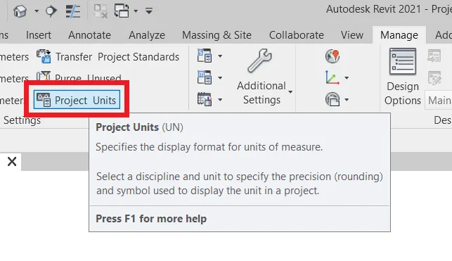
- Project units
Procedure:
Step1- To open a project file with an architectural template and to save the file with the appropriate name.
- Click on new and in the dialogue box select architectural template.
- Click on the file and then click on save. Name the project and select the location of the project to be saved.
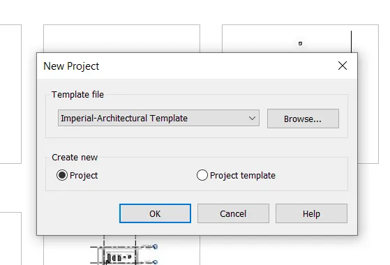
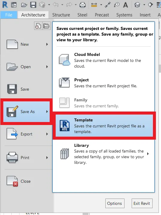
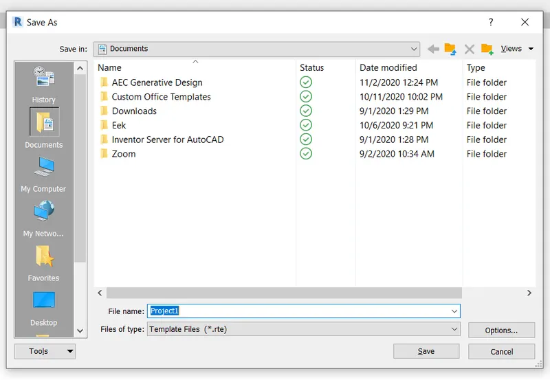
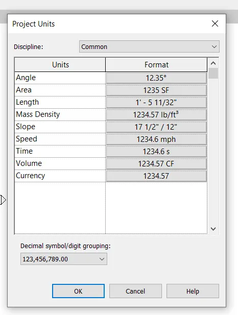
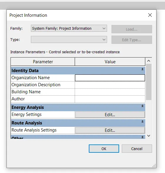
Step2-To set up the project units to Imperial / Metric based on your convenience of modeling and complete the project information under the Manage tab.
- Go to manage and click on project units.
- A dialog box opens up. Change the units as desired.
- Click on project information in the manage toolbar.
- fill in the information and click ok.
Step3-To last set up the maximum backups for the project file to 3.
- In the file go to save as and click in the project.
- in the dialog box opened click on options.
- in file save options enter the maximum backups for the project file as 3.
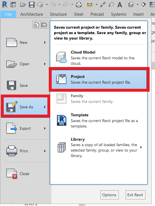

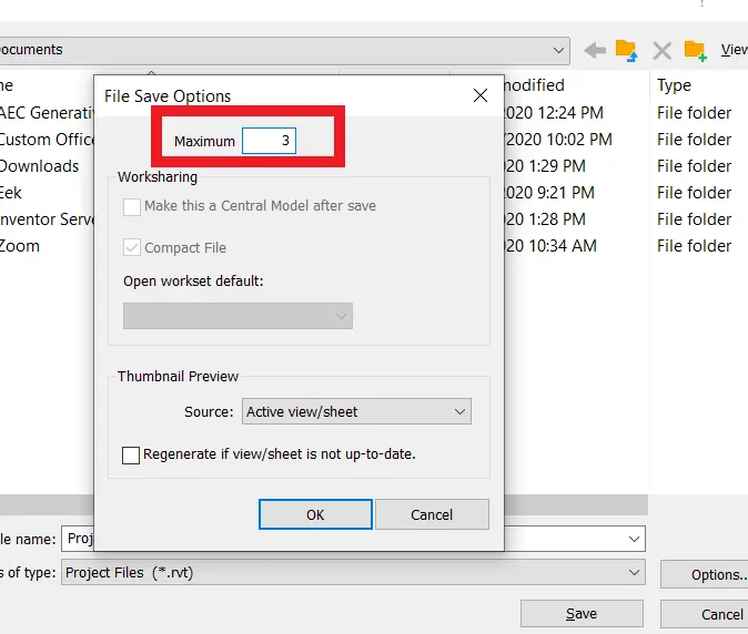
Result: All tasks were successfully completed using Revit software 2021.
----------------------------------------------------------------------------------------------------------------------------------
4) Understand the concept of Levels and Grids. Follow the naming and conventions. Create the following Levels: ( Convert to metric equivalents if metric is your units)
Ground Floor @ 0’
First Floor @ 10’
Second Floor @ 20’
Roof @ 30’
Grids Transverse Grids A, B,C,D, E @ 10’ spacing
Longitudinal Grids from 1 to 10 @ 20’ spacing
ANS)
Aim:- To understand the concept of Levels and Grids and create the following Levels:
( Convert to metric equivalents if the metric is your units)
Ground Floor @ 0’
First Floor @ 10’
Second Floor @ 20’
Roof @ 30’
Grids Transverse Grids A, B, C, D, E @ 10’ spacing
Longitudinal Grids from 1 to 10 @ 20’ spacing
Tools used:
- level
- Grid
Procedure:-
Step1:- the concept of levels.
- From the architecture menu in the datum section click on a level to add levels.
- to add levels, one must open an elevation view.
- Enter the desired distance below the label where the distance between levels is shown to change the distance.
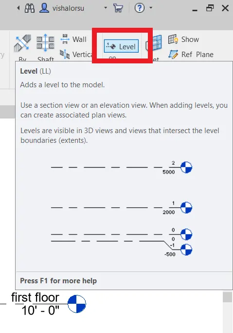
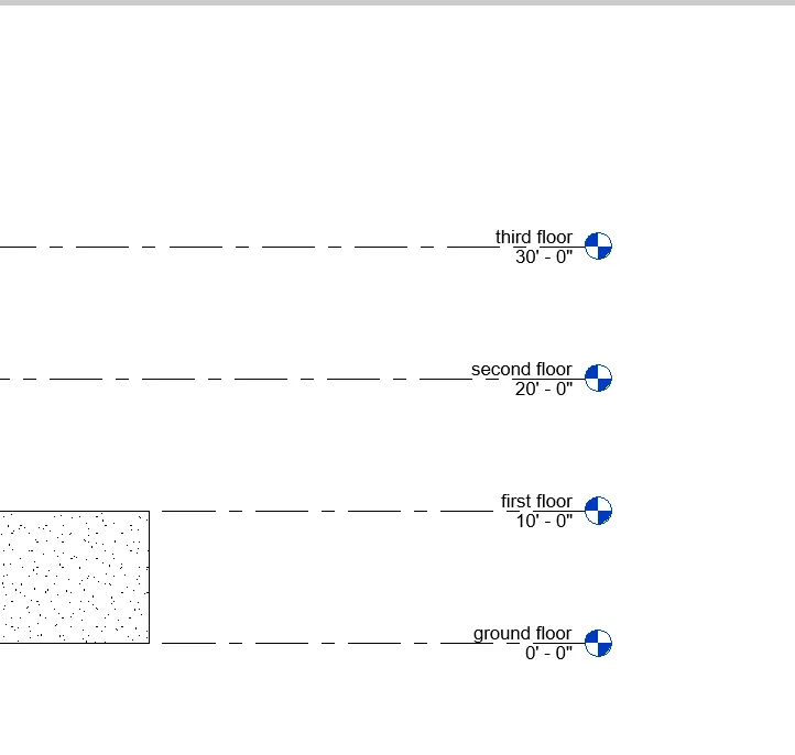
Step2-: the concept of Grids.
- From the architecture menu in the datum section click on the grid to ad grids
- horizontal grids are tagged with alphabets and vertical with numerical.
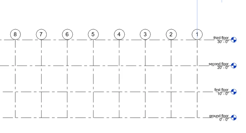
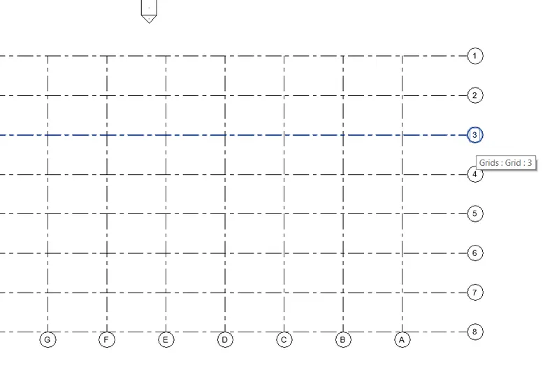
Result: Given grids and levels were made by using Revit successfully.
----------------------------------------------------------------------------------------------------------------------------------
5) 3D modelling of residential unit – From looking at your house / or a place you aspire. Create a conceptual layout of the residential unit. You can measure using a tape or you can access your residential plan to create a similar layout.
ANS)
Aim: To create a 3D modeling of the residential unit layout.
Tools used:
- wall tool
- properties browser
- Room
Procedure:
- From the architectural toolbar select walls.
- draw the desired wall layout.
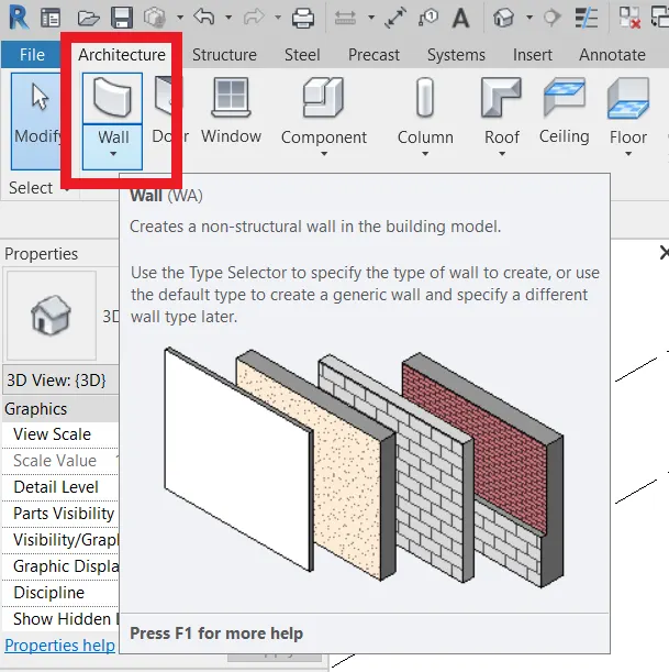
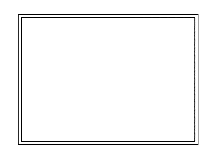
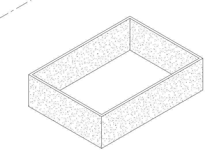
Result: Created residential unit layout.
----------------------------------------------------------------------------------------------------------------------------------
6) In the layout created draft the level of details you are planning to include – Dimensions of room, components you plan to add in the residential unit.
ANS)
AIM: In the layout created draft the level of details you are planning to include – Dimensions of room, components you plan to add in the residential unit.
Tools used:
- walls.
- architecture toolbar.
- room.
Procedure:
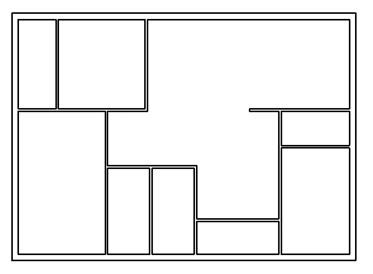
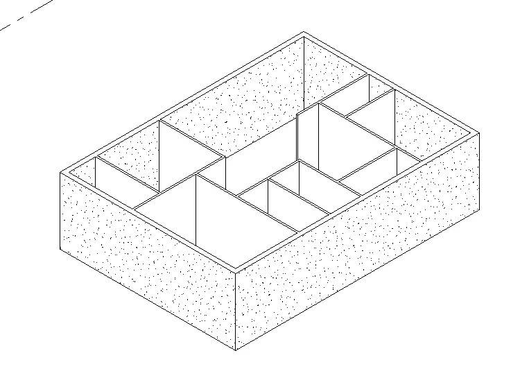
Step1:- adding interior walls.
- select walls, from properties browser change wall to interior wall.
- mark the walls as desired and make rooms.
Step2- Naming rooms
- from the architecture menu in from room and area section select room.
- click on closed interior spaces to name them.
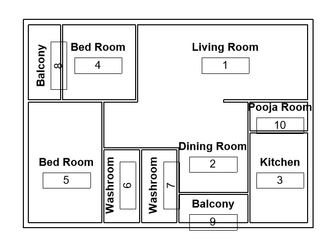
Result: drafting is successfully completed in the layout created.
----------------------------------------------------------------------------------------------------------------------------------
7) Identify the residential model elements such as Door, Windows, Tables, Chair, Couch, Bed, Lamps from the library and insert them to the model . Save the project for use for Assignment 3
ANS)
Aim: To identify the residential model elements such as Door, Windows, Tables, Chair, Couch, Bed, Lamps from the library and insert them to the model
Tools used:
- insert
- load family
- component
- properties browser
Procedure:
- Go to insert from tool bar.
- Click on the load family from the import section.
- From the dialog box select the required family to be loaded.
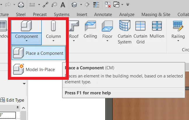
- From the architectural menu click component to use the model elements selected from the insert.
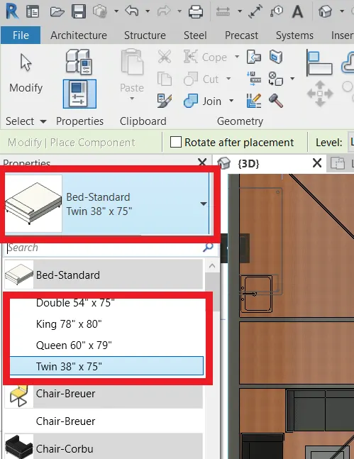
- from the properties browser, we can change the size of the elements
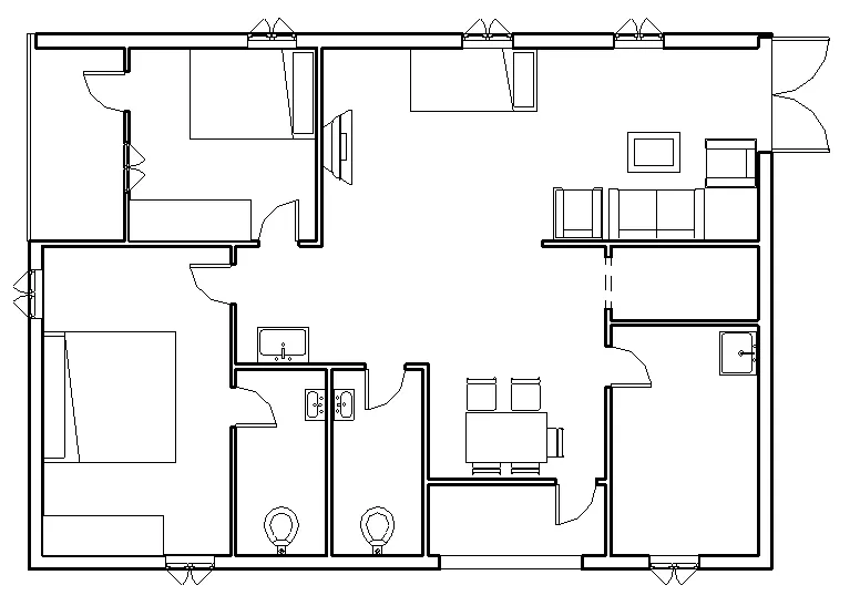
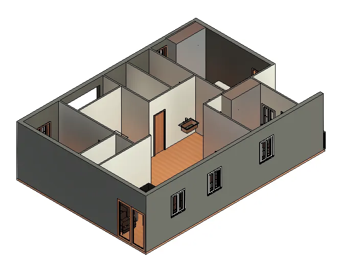
Result:- Identifying the residential model elements such as Door, Windows, Tables, Chair, Couch, Bed, Lamps from the library, and inserting them into the model is done successfully.
-------------------------------------------------------------*****--------------------------------------------------------------