Reinforcement detailing of Columns from ETABS output
Reinforcement detailing of columns in Etabs 2018.
The ETABS file for a G+4 building is provided. Run the analysis and design the RCC Moment Resisting Frame. The following challenge deals specifically with two columns at the following grid intersections.
- 3A
- 3B
- Provide details of longitudinal reinforcement for the two columns, from foundation to terrace level. Sketch the column cross sectional & elevation details or draft it using autocad software.
- Show shear reinforcement & lapping details as per special confining reinforcement provision of clause 8.1 of IS 13920 - 2016.
ANSWER:-
Aim:- To provide,
The details of longitudinal reinforcement for the two columns (3A & 3B), from foundation to terrace level.
The details of shear reinforcement as per special confining reinforcement provision of clause 8.1 of IS 13920 - 2016.
Introduction:-
- A reinforced concrete column is a structural member designed to carry compressive loads, composed of concrete with an embedded steel frame to provide reinforcement.
- For design purposes, the columns are separated into two categories: short columns and slender columns.
- A short column is a structural member whose relatively short length virtually ensures it will fail in compression if it is evenly loaded along its axis.
- Columns can be classified as short, intermediate, or long, depending on their lengths, their material properties, and the lengths of other columns in the same structure.
- A slender column is a thin column. For any construction, foundation starts with marking the position of columns and then their design and analysis.
- Slender column can be tested in laboratory to observe the action of buckling or cripping. For a column,based on slenderness ratio, it is termed as long or short column.
Procedure:-
Step:-1
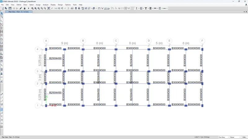
- First we have to open the etabs models in challange 7 attachment model.
- After downloading the attachment model open it in the etabs 2018, as shown below.
Step:-2
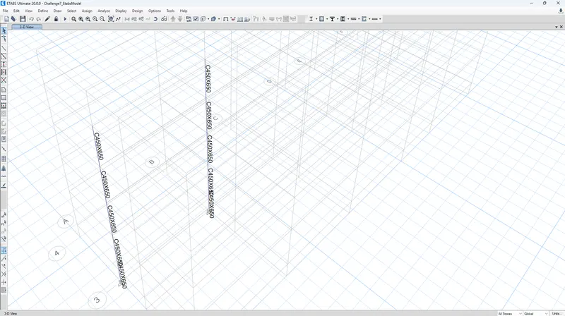
Open the terrace level plan view and select the all stories & next select the column (3,A) & (3,B).
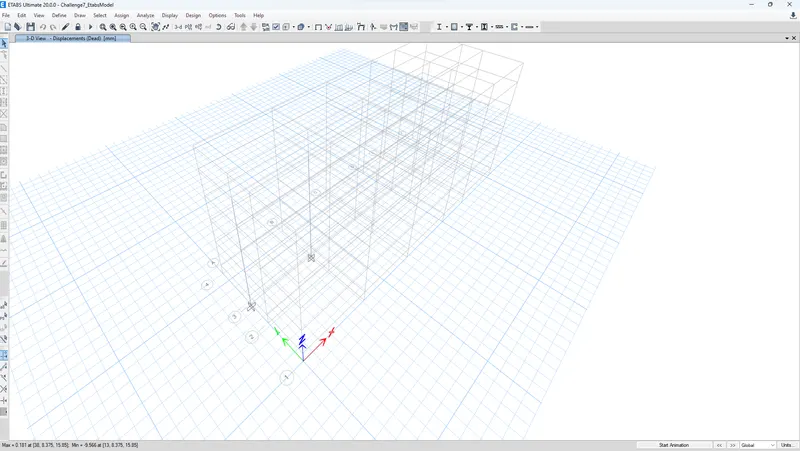
Next Select The blank page and click the right click & chose the show selected object only options& Run analysis.
Next Check the Maximum &Minimum deflection of column value.
Step:-3
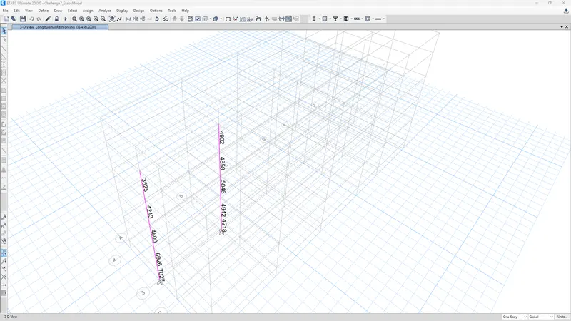
Select the concrete frame design buttons.
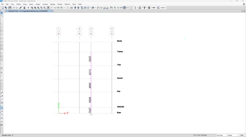
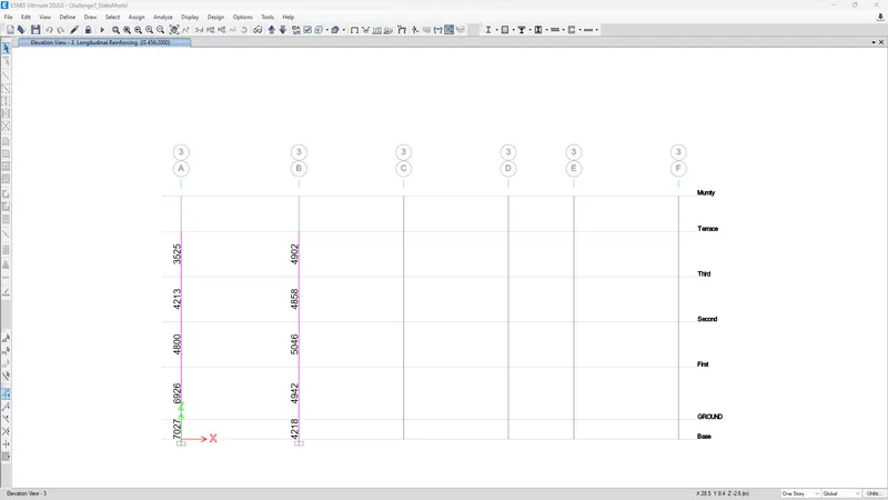
Next select the elevation view & select elevation along 3A&3B.
Step:-4
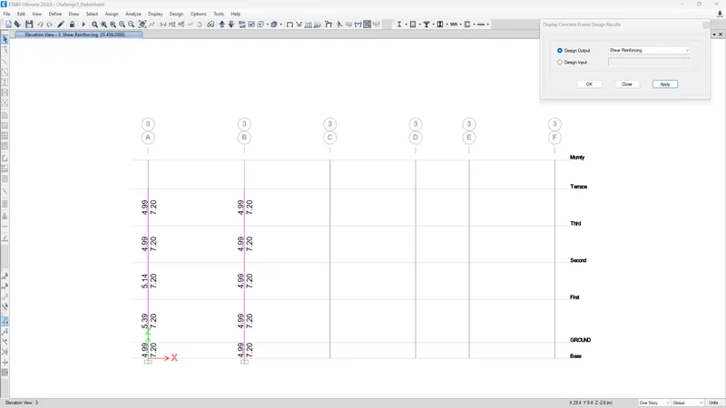
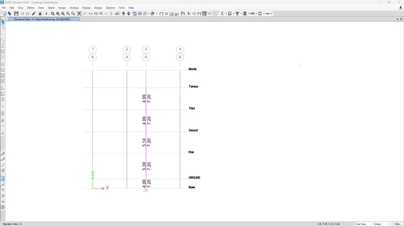
Select the concrete buttons & chose the display design info & select the shear reinforcing3A&3B.
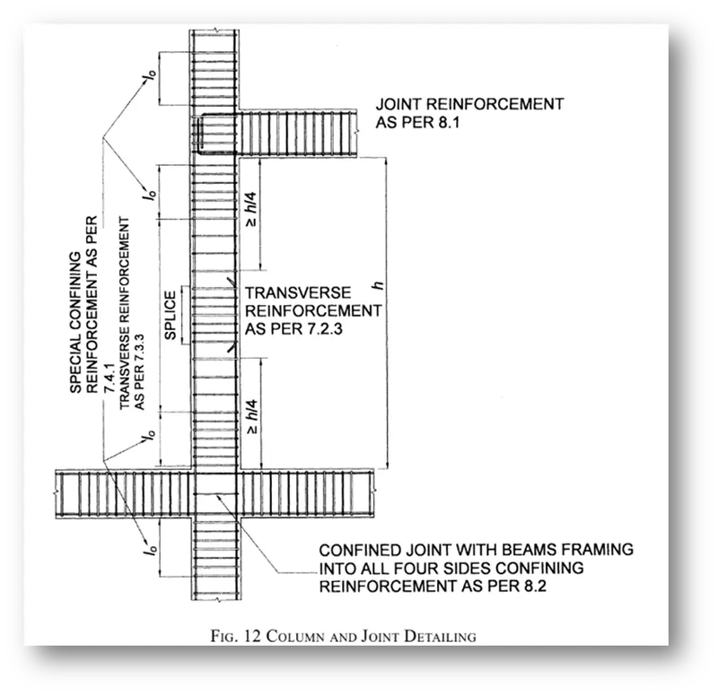
Special confining reinforcement from IS-13920-2016(Clause 8.1)
Lo not less than-
- Larger column dimension
- 1/6 of clear span of column
- 450 mm
Confinement spacing not more than-
- ¼ of smaller column dimension
- 6 times of dia of column main bar
- 100mm
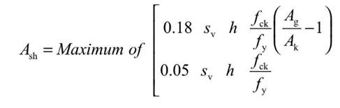
The amount of confinement rebar- .
Step 6:
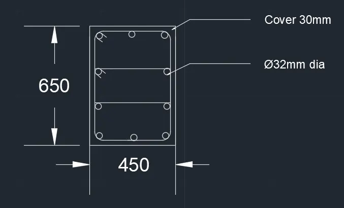
GRID A:
1) From Base to first floor the maximum Ast is = 7027
2) So we can provide 10nos of 32mm dia bar = 10 x 804
= 8040mm^2
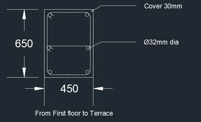
3) From First floor to Terrace the maximum Ast is = 4800
4) So, We can provide 6nos of 32mm dia bar = 6 x 804
= 4824mm^2
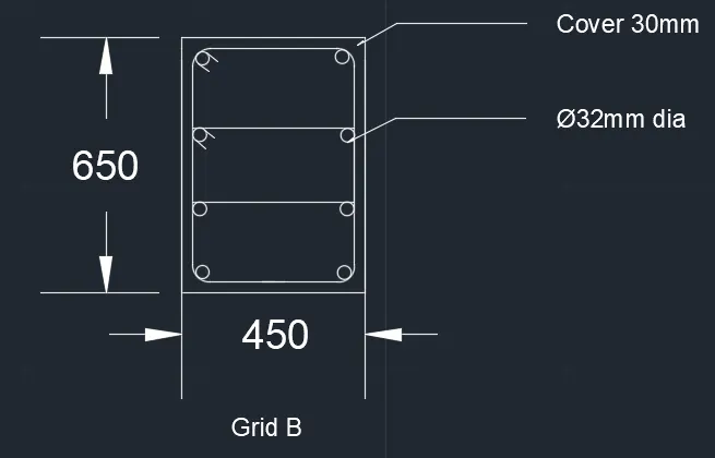
GRID B:
1) From Base to Terrace the maximum Ast is = 5046
2) So we can provide 8 nos of 32mm dia bar = 8 x 804
= 6432mm^2
Therefore it can be satisfied entire span.
RESULT:-
- Provided the details of longitudinal reinforcement for the two columns (3A & 3B) successfully, from foundation to terrace level.
- Provided the details of shear reinforcement as per special confining reinforcement provision of clause 8.1 of IS 13920 - 2016.
- And also provided the column cross sectional & elevation details using the AutoCAD software.