Reinforcement detailing of Columns from ETABS output
AIM:
In the given etabs project we have to analyse and redesign the RCC moment resisting frame in two columns at the following grid intersection 3A & 3B from foundation to terrace level by using etabs with reference of IS 13920-2016
INTRODUCTION:
In the modal we provide the details of longitudinal reinforcement of two columns and shown shear reinforcement, lapping details as per special confining zone of clause 8.1 of IS 1920-21016
PROCEDURE:
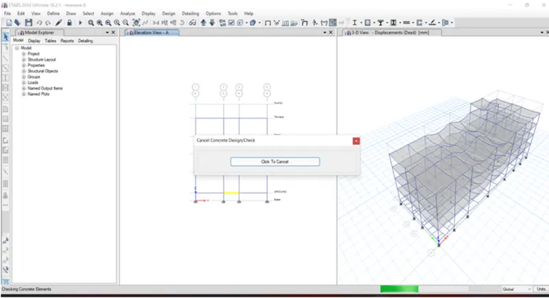
- Model open in etabs software
- Check the model
- Select the column intersection 3A & 3B from terrace to foundation
- Click on run analysis it will show the max. & min. deflection at the bottom
- Click on concrete frame design icon
- It will show the longitudinal reinforcement of the column
- Select the elevation view along the grid 3
- Drop down the icon concrete frame design and click on display design info
- Select shear reinforcement in display concrete frame design
- By observing the given data of longitudinal reinforcement.
- Provide as possible no of reinforcement required.
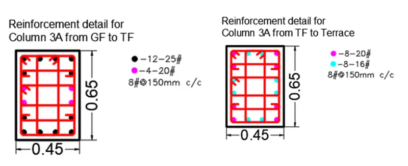
- In 3A the Column size was 450mmx650mm
- Hence it required 6939mm2 reinforcement hence provide 12no. of 25 dia bars and 4no. of 20mm dia bars as shown.
- The above detail is from GF to Third floor
- There after the rebars changes to 8no. of 20mm dia and 8no. of 16mm dia bars upto the terrace as shown below.
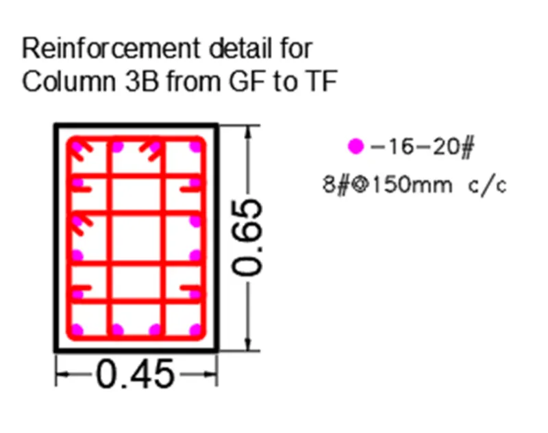
- In 3B the Column size was 450mmx650mm
- Hence it required 4918mm2 reinforcement hence provide 16no. of 20 dia bars as shown.
- The above detail is from GF to Third floor
- There after the rebars changes to 16no. of 16mm dia upto the terrace as shown below.
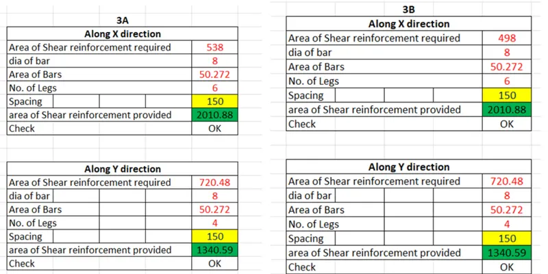
For Shear Reinforcement just change the option as show shear reinforcement then it shows as shown below
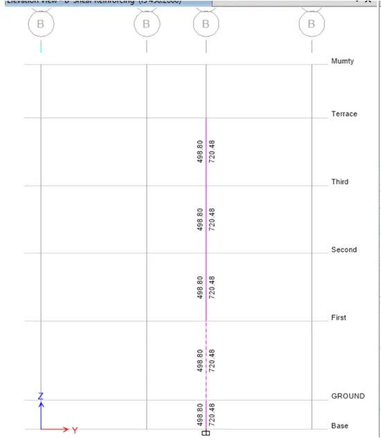
- Hence there is a excel sheet is created wich calculate the no. of Shear reinforcement required
- in which is calculated by formula Ast provided=(1000*no. of legs*ast of stirrup)/Spacing of Stirrup
- Any how in the sismic design evers bar is connected with stirrups and hooks as shown below,
Flexural yielding is likely in beams during strong earthquake shaking and in columns when the shaking intensity exceeds the expected intensity of earthquake shaking This special confining reinforcement shall,
- be provided over a length 1, from the face of the joint towards mid-span of beams and mid heights of columns, on either side of the joint; where /is not less than
- larger lateral dimension of the member at the section where yielding occurs,
- 1/6 of clear span of the member
- 450 mm.
- have a spacing not more than,
1) 1/4 of minimum member dimension of the in beam or column
2) 6 times diameter of the smallest the longitudinal reinforcement bars; and
3)100 mm link.
RESULT:
Successfully done the designing and detailing of provided the details of column reinforcement at grid 3A & 3B from foundation to terrace level as per IS 13920:2016 clause 8.1 and sketch the cross section/ elevation in AutoCAD software