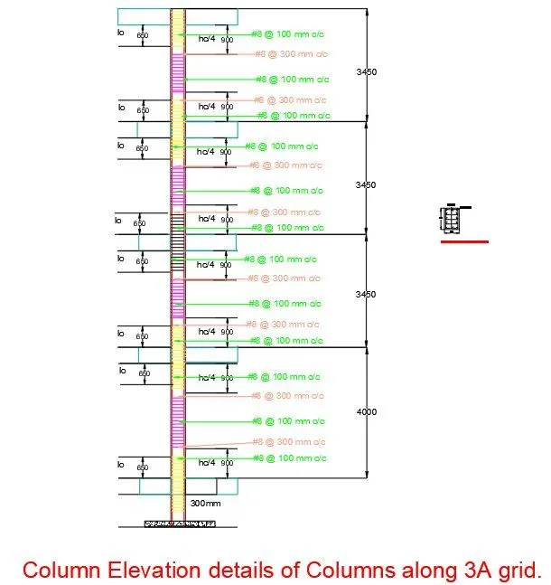
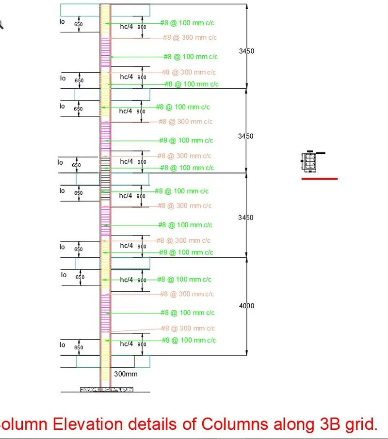
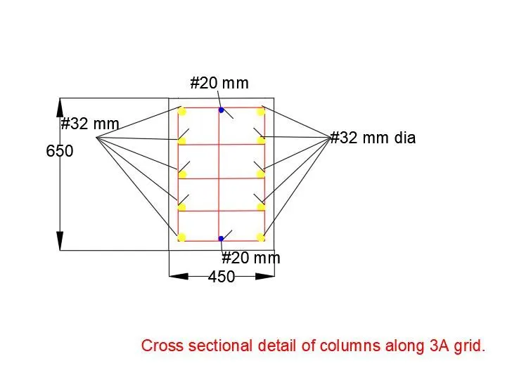
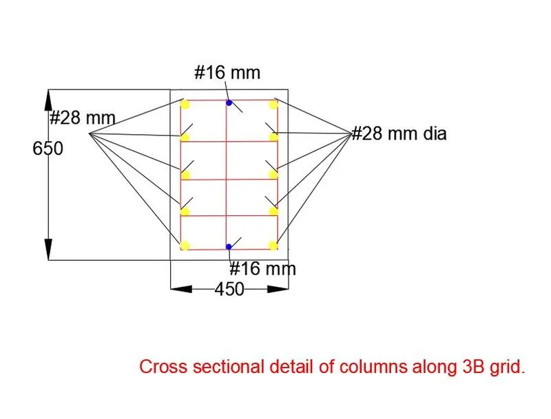
Reinforcement detailing of Columns from ETABS output
Ans:-
Aim:- To provide the longitudinal Reinforcement of the columns from foundation to Terrace level and to sketch the column cross sectional and elevation details in Autocad.
To show the shear reinforcement and lapping details as per Clause 8.1 of IS 13290-2016.
Introduction:
1.in the first step the given model is Set for run option.
2.Once the Analysis is completed, then the concrete frame design option is clicked.
3.Now the under the concrete frame design option select the option display design info and click longitudinal Reinforcement.
4.Longitudinal reinforcement will be visible, note the values of the reinforcement required.
4.In the next Step note down the shear reinforcement details.
- Start the design and detailing.
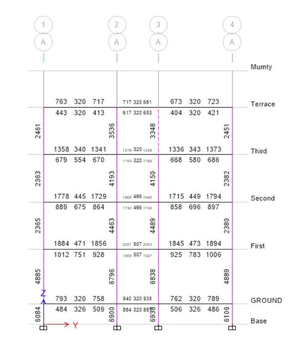
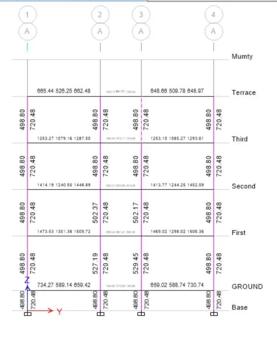
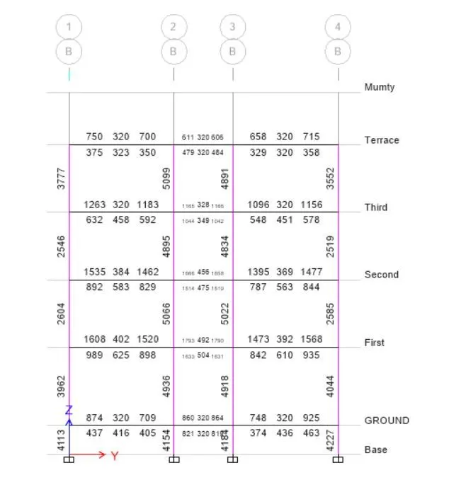
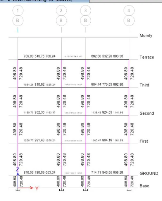
| COLUMN DESIGN | ||||
| COLUMNS ALONG THE GRID 3A | Column dimension | 450*650 | ||
| 1 | Longitudinal Reinforcment calculation | |||
| a) | Minimum Reinforcment | 0.8% of Gross cross sectional Area | 2340 | mm^2 |
| As per clause no.26.5.3.1 of Is 456 2000 | ||||
| b) | Maximum Reinforcment | 6% of Gross cross sectional Area | 17550 | mm^2 |
| As per clause no.26.5.3.1 of Is 456 2000 | ||||
| c) | Maximum Ast along 3 A | 6938 | mm^2 | |
| As per clause no.26.5.3.1 of Is 456 2000 | ||||
| Dia of the longitudinal Reinforcment should 12 mm or more | ||||
| There for using 16 mm dia bars | ||||
| Dia of bar | 32 | |||
| Area of 1 bar | 804.352 | |||
| number of bars | 8.625576862 | |||
| There fore using 8 number of 32 mm dia bars | Ast | 6434.816 | ||
| Remaning Ast | Ast | 503.184 | ||
| There for using 16 mm dia bars | ||||
| Dia of bar | 20 | |||
| Area of 1 bar | 314.2 | |||
| number of bars | 1.601476766 | |||
| There fore using 2 number of 20 mm dia bars | Ast | 628.4 | ||
| There fore total longitudinal reinforcment provided | ||||
| 8 no. of 32 mm dia bars | ||||
| 2no. Of 20 mm dia bars | ||||
| Ast provided | 7063.216 | mm^2 | ||
| The spacing between the longitudinal bars should not exceed 300mm. | ||||
| 2 | Shear Reinforcment calculation | |||
| a) | Minimum dia for shear Reinforcment for 32 mm dia | 8 mm | ||
| As per clause no 7.4.2 of IS 13290- 2016 | ||||
| b) | Maximum Shear reinforcment from the Etabs out put | 720.48 | mm^2 | |
| c) | There for using 8 mm dia bars | mm^2 | ||
| Dia of bar | 8 | |||
| Area of 1 bar | 50.272 | |||
| Special confining reinforcement clause no 8 of IS 13290 2016 | ||||
| The special cofining reinforcement shall be provided at lo. | ||||
| lo should not be less tham | ||||
| larger lateral dimension of the column | 650mm | |||
| 1/6 of the clear span of member | 554.1666667 | |||
| 450 mm | 450 | |||
| There fore lo = 650 mm | ||||
| The spacing of shear reinforcment along lo should not be more than | ||||
| a | 1/4 of minimum dimension of beam/column | |||
| minimum dimension of column | 450 | mm | ||
| 1/4th of minimum dimension of column | 112.5 | mm | ||
| b | 6 times the dia of smallest longitudinal reinforcement bar | |||
| Dia of smallest longitudinal reinforcement bar | 20 | mm | ||
| 6 times the dia of smallest longitudinal reinforcement bar | 120 | mm | ||
| c | 100 mm | 100 | mm | |
| There fore for special confining reinfrocemnet #8mm @100 mm c/cis provided in the lo zone. | ||||
| Transverses Reinforcment calculation for the zone upto h/4. | ||||
| hc in m | Beam depth | h | ||
| Height of the column of Plinth level column | 1.5 | 0.5 | 1 | |
| Height of the column ofGF column | 4 | 0.5 | 3.5 | |
| Height of the column of FF column | 3.45 | 0.5 | 2.95 | |
| Height of the column of SF column | 3.45 | 0.5 | 2.95 | |
| Height of the column of TF column | 3.45 | 0.5 | 2.95 | |
| 3.45 | 0.5 | 2.95 | ||
| h | h/4 | approximate | ||
| Plinth level | 1 | 0.25 | 300 mm | |
| GF | 3.5 | 0.875 | 900 mm | |
| FF | 2.95 | 0.7375 | 900 mm | |
| SF | 2.95 | 0.7375 | 900 mm | |
| TF | 2.95 | 0.7375 | 900 mm | |
| Transverse reinforcement in the splice Zone as per clause number 7.4.of IS 13290 2016 | ||||
| As per the clause nuo. 7.4.1 of IS 13290 2016 the ends should have 135 hook with an | ||||
| extension of 6d of bars. | ||||
| d | 32 | mm | ||
| 6d | 192 | mm | ||
| As per the clause nuo. 7.4.2 of IS 13290 2016 | ||||
| a | 8 mm dia bars are used in stirrups if the dia of longitudinal bars is less than or equal to 32 mm | |||
| b | The maximum c/c spacing of stirrups is 300 mm | |||
| c | a cross tie should be provided if the dimension of the column exceeds 300 mm. | |||
| There fore upto h/4 #8mm @300 mm c/cis provided in the lo zone. | ||||
| As per the clause no. 7.3.2.1 of IS 13290 2016 | ||||
| 100 mm spacng should be provided within this splicing zone | ||||
| There fore in the splice zone #8mm @100 mm c/cis provided in the lo zone. | ||||
| For the columns terminating in the footing | ||||
| as per clause nummber 8.2 of IS 13290 2016. | ||||
| special confinement reinforcement should be provided upto 300 mm or larger length inside the footing. | ||||
| COLUMNS ALONG THE GRID 3B | Column dimension | 450*650 | ||
| 1 | Longitudinal Reinforcment calculation | |||
| a) | Minimum Reinforcment | 0.8% of Gross cross sectional Area | 2340 | mm^2 |
| As per clause no.26.5.3.1 of Is 456 2000 | ||||
| b) | Maximum Reinforcment | 6% of Gross cross sectional Area | 17550 | mm^2 |
| As per clause no.26.5.3.1 of Is 456 2000 | ||||
| c) | Maximum Ast along 3 A | 5022 | mm^2 | |
| As per clause no.26.5.3.1 of Is 456 2000 | ||||
| Dia of the longitudinal Reinforcment should 12 mm or more | ||||
| There for using 16 mm dia bars | ||||
| Dia of bar | 28 | |||
| Area of 1 bar | 615.832 | |||
| number of bars | 8.154821445 | |||
| There fore using 8 number of 32 mm dia bars | Ast | 4926.656 | ||
| Remaning Ast | Ast | 95.344 | ||
| There for using 16 mm dia bars | ||||
| Dia of bar | 16 | |||
| Area of 1 bar | 201.088 | |||
| number of bars | 0.474140675 | |||
| There fore using 2 number of 20 mm dia bars | Ast | 402.176 | ||
| There fore total longitudinal reinforcment provided | ||||
| 8 no. of 28 mm dia bars | ||||
| 2no. Of 16 mm dia bars | ||||
| Ast provided | 5328.832 | mm^2 | ||
| The spacing between the longitudinal bars should not exceed 300mm. | ||||
| 2 | Shear Reinforcment calculation | |||
| a) | Minimum dia for shear Reinforcment for 32 mm dia | 8 mm | ||
| As per clause no 7.4.2 of IS 13290- 2016 | ||||
| b) | Maximum Shear reinforcment from the Etabs out put | 720.48 | mm^2 | |
| c) | There for using 8 mm dia bars | mm^2 | ||
| Dia of bar | 8 | |||
| Area of 1 bar | 50.272 | |||
| Special confining reinforcement clause no 8 of IS 13290 2016 | ||||
| The special cofining reinforcement shall be provided at lo. | ||||
| lo should not be less tham | ||||
| larger lateral dimension of the column | 650mm | |||
| 1/6 of the clear span of member | 554.1666667 | |||
| 450 mm | 450 | |||
| There fore lo = 650 mm | ||||
| The spacing of shear reinforcment along lo should not be more than | ||||
| a | 1/4 of minimum dimension of beam/column | |||
| minimum dimension of column | 450 | mm | ||
| 1/4th of minimum dimension of column | 112.5 | mm | ||
| b | 6 times the dia of smallest longitudinal reinforcement bar | |||
| Dia of smallest longitudinal reinforcement bar | 20 | mm | ||
| 6 times the dia of smallest longitudinal reinforcement bar | 120 | mm | ||
| c | 100 mm | 100 | mm | |
| There fore for special confining reinfrocemnet #8mm @100 mm c/cis provided in the lo zone. | ||||
| Transverses Reinforcment calculation for the zone upto h/4. | ||||
| hc in m | Beam depth | h | ||
| Height of the column of Plinth level column | 1.5 | 0.5 | 1 | |
| Height of the column ofGF column | 4 | 0.5 | 3.5 | |
| Height of the column of FF column | 3.45 | 0.5 | 2.95 | |
| Height of the column of SF column | 3.45 | 0.5 | 2.95 | |
| Height of the column of TF column | 3.45 | 0.5 | 2.95 | |
| 3.45 | 0.5 | 2.95 | ||
| h | h/4 | approximate | ||
| Plinth level | 1 | 0.25 | 300 mm | |
| GF | 3.5 | 0.875 | 900 mm | |
| FF | 2.95 | 0.7375 | 900 mm | |
| SF | 2.95 | 0.7375 | 900 mm | |
| TF | 2.95 | 0.7375 | 900 mm | |
| Transverse reinforcement in the splice Zone as per clause number 7.4.of IS 13290 2016 | ||||
| As per the clause nuo. 7.4.1 of IS 13290 2016 the ends should have 135 hook with an | ||||
| extension of 6d of bars. | ||||
| d | 32 | mm | ||
| 6d | 192 | mm | ||
| As per the clause nuo. 7.4.2 of IS 13290 2016 | ||||
| a | 8 mm dia bars are used in stirrups if the dia of longitudinal bars is less than or equal to 32 mm | |||
| b | The maximum c/c spacing of stirrups is 300 mm | |||
| c | a cross tie should be provided if the dimension of the column exceeds 300 mm. | |||
| There fore upto h/4 #8mm @300 mm c/cis provided in the lo zone. | ||||
| As per the clause no. 7.3.2.1 of IS 13290 2016 | ||||
| 100 mm spacng should be provided within this splicing zone | ||||
| There fore in the splice zone #8mm @100 mm c/cis provided in the lo zone. | ||||
| For the columns terminating in the footing | ||||
| as per clause nummber 8.2 of IS 13290 2016. | ||||
| special confinement reinforcement should be provided upto 300 mm or larger length inside the footing. |
7.column detailing drawings