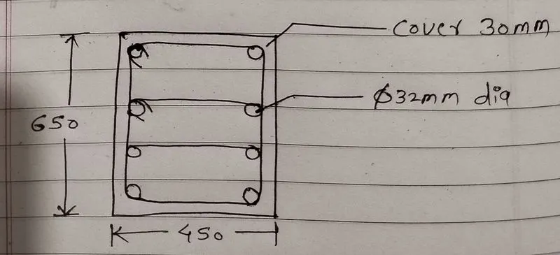
Reinforcement detailing of Columns from ETABS output
- AIM : To provide details of logitudinal and shear reinforcement for the two columns from foundation to terrace level.
PROCEDURE : - First of all open the ETABS software.
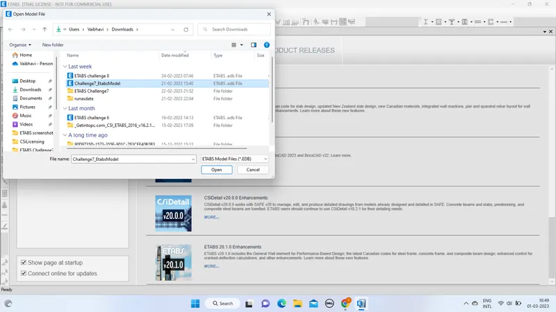
- Then go the File tab from there go to the open option and then open the previous file for the analysis of the column of the G+4 building just as shown in below given image :
- Now the file on which we want to run the analysis is open just as shown in the below image :
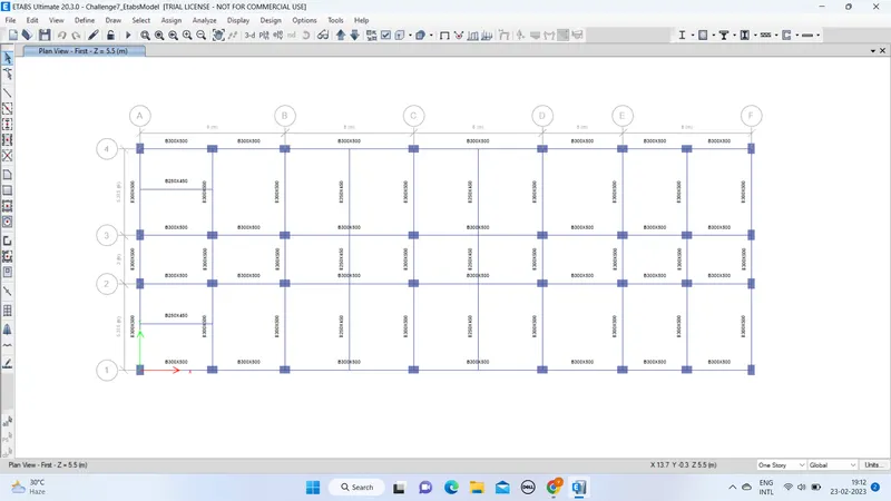
- Now after opening the file the very first thing which we need to do Run Analysis.
- So in order to do the run analysis first of all go to the Analysis tab at the top of screen and then at the drop-down list there is an option called Run Analysis click on it.
- Or else we can also press F5 or there is an another option at the top of the screen to perform the Run Analysis.We can choose any option.
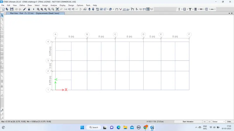
- So now.run analysis have been done here is just as shown in below image :
- After doing the Run Analysis next we have to go to Design toolbar after clicking on the option Design there is a drop-down list of different options and from that option just click on the option Concrete Frame Design and then click on another option called View/Revise preferences just as shown in below image :
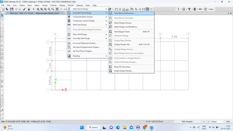
- So after clicking on the option View/Revise Preferences there is a new dialouge box named as Concrete Frame Design Preferences for IS456:2000 just as shown in below figure :
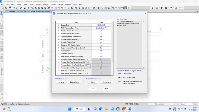
- After confirming the codal standards we need to choose the 2 columns which we are going to analyse and design.
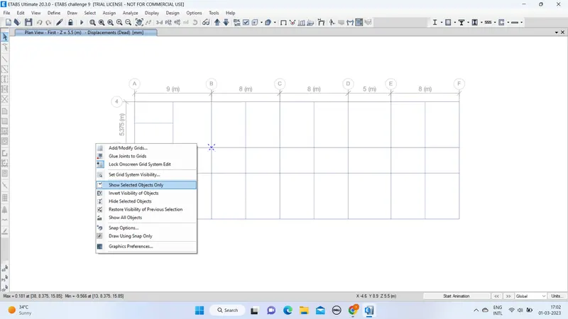
- Now select the column which we are going to analyse and do the detailing process change the view setting to only the selected columns.
- For this just click there will be a drop-down list of different options from that list choose the option Show Selected Objects Only just as shown in below image :
- Now do the run analysis.
- After this,just press the Concrete Frame Design icon which is available at the top right side of the screen.
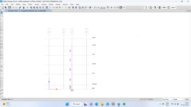
- So the longitudinal reinforcement results are comes.
- After this just go to the Elevation view along the grid A.
- So in order to view the elevation view just press the Elevation button present at top-middle of the screen or just go to View option then there will be aa drop-down list from that list choose the option Set Elevation View or just press Shift + Control+F2 any method will work.
- Now after clicking the elevation view option there will be another dialogue box named as Set Elevation View. From that dialogue box choose the elevation view A.
- And below is the column results along grid A :
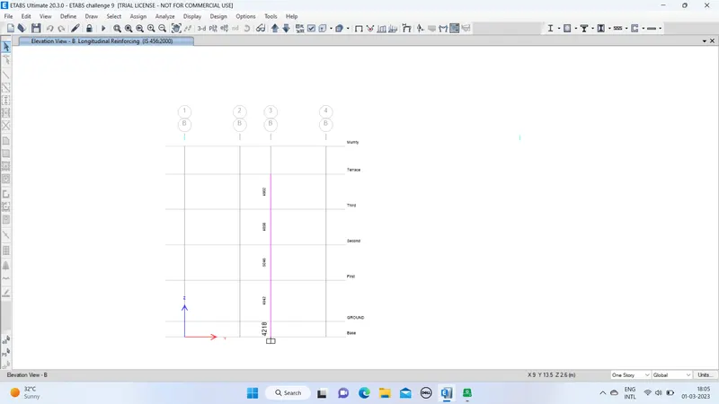
- And below is the column results along grid B :
- After if we want check the shear reinforcement then go to the concrete frame design and click on Display Design info from the drop-down list.
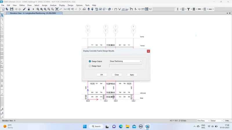
- After clicking on that a new dialogue box open named as Display Concrete Frame Design Results , in that box change the option Total longitudinal Reinforcing into Shear Reinforcing just asshown below :
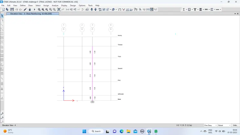
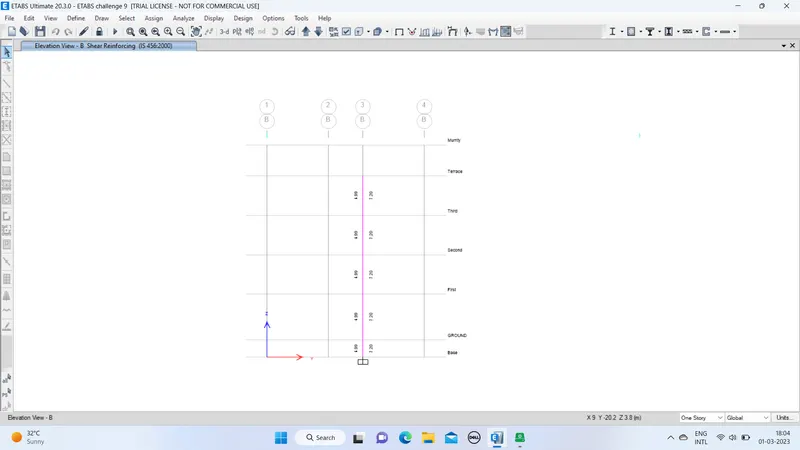
- Now we will be checking the elevation from base to terrace.
- So in order to check the elavations first we need to go to the option Edit and then click on Edit Stories.
- After clicking on Edit Stories click on modify option.
- Below is the given result :
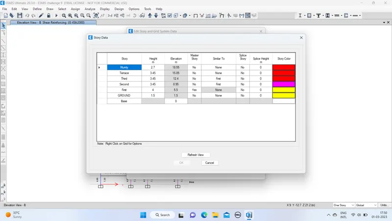
- Use these values when we are detailing the columns,so we should values of the heights and elevations of the G+4 story building
GRID A - From base to the first floor the maximum Ast = 7027
- So we can provide 10 Nos. of 32mm Dia.bars = 10*804 = 8040mm^2
- From the first floor to terrace the maximum Ast = 4800
- Provide 6 Nos.of 32mm Dia.bar = 6*804 = 4824mm^2
GRID B - From base to terrace the maximum Ast = 5046
- Provide 8 Nos. of 32mm Dia.bar = 6432mm^2
It can satisfy the entire span
RESULT :
The given reinforcement details of Column is created using ETABS.
Columns detail drawing for grid 3A :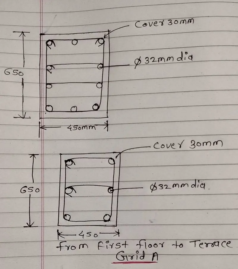
Columns detail drawing for grid 3B :