Reinforcement Detailing of Beams from ETABS output
Ans)
AIM: To design the beams in detail from the ETABS 2018
To provide details of longitudinal and shear reinforcement for the given two continous beams.
To calculate the value of maximum shear force in any one of the spans in the continous beams.
INTRODUCTION
- Beams are horizontal structural elements used for the supporting lateral loads.
- In conventional reinforcement concrete structures, beams usually receive load from the floor slab, but may also be subjected to other loads such as wall loads, finishes, services installation, etc.
- The design and detailling of Rc beams involves the selection of the proper beam size and the qunitiy of longitudianl and shear reinforcement that will satisy ultimate and the ultimate and serviceability limit state requirements.
- Afterwards, it is very important that the beams reinforcement are placed and arranged properly on site, to avoid construction error.
PROCEDURE:
Step:-1
- First we have to open the challange 7 page and download the challenge.
- After downloading the challenge open it in the etabs 2018, as shown below.
STEP:-2
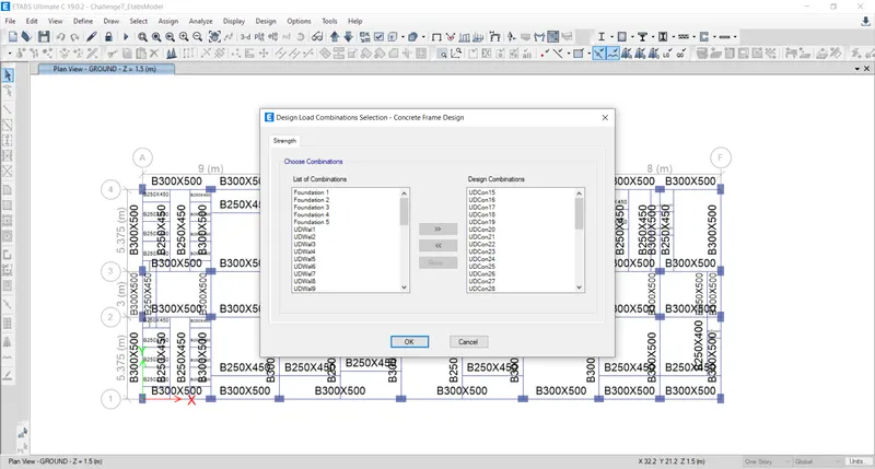
- Next we have to check the load combinations, as shown below.
Step:-3
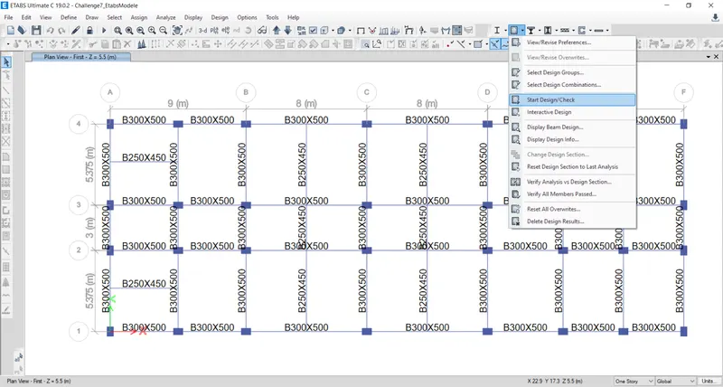
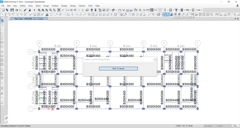
- Next we have to start the beam design by selecting the start Design /check' option as , shown below.
Step:-4
- After the completion of the beam design, we need to select the ' Display Design info' option, as shown below.
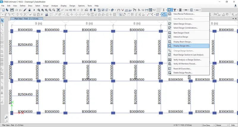
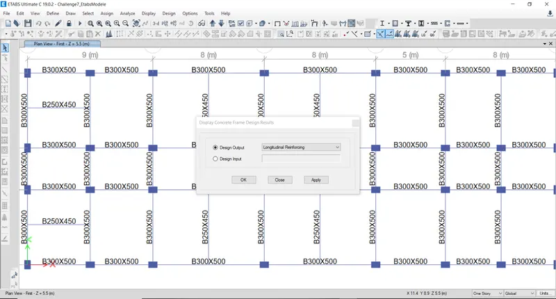
- After selecting the 'Display Design info' option the new tab appears, In that we select the Longitudinal Reinforcing in the Design Output and click on the Ok button, as shown below.
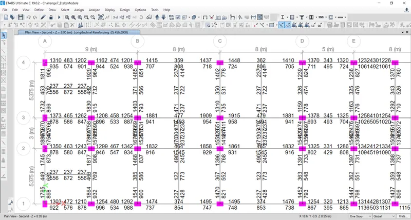
- Next the logitudinal reinforcement details will appear, as shown below.
Step:-5
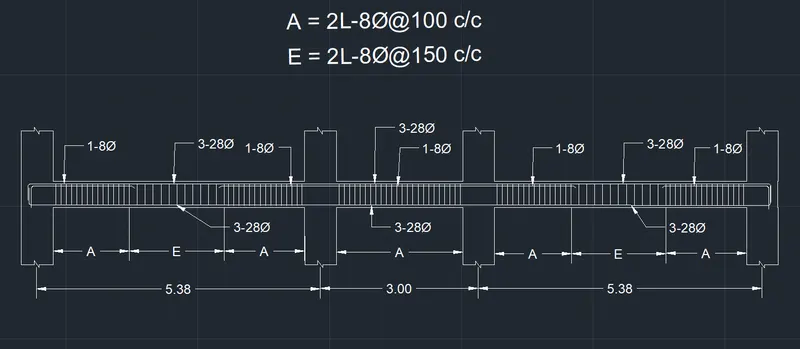
- Next we need to draw the Reinforceent diagram of 3span continous beam along Grid-A, and also need to provide the reinforcement details.
- The maximum Ast for the bottom support is 1766mm^2 and botttom middle is 702mm^2
- The maximum Ast for the top support is 1889mm^2 and top middle is 702mm^2
- Now we provide 3- 28 at the top and bottom, as shown in the below figure.
- Next we provide 1-8 at the top supports for the continuos beam, as shown below.
Step:-6
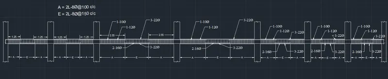
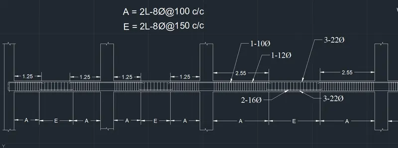
- Next we need to draw the Reinforcement diagram of 7 span continous beam along Grid-3 and also need to provide the reinforcement details.
- The maximum Ast for the bottom support is 1061mm^2 and top middle is 479mm^2
- Now we provide 3-22 at the top and bottom, as shown in the below figure.
- Next we provide 1-10 and 1-12 at the top supports and we provide 2-16 at the bottom middle for the continous beam, as shown below.
Step-7
- After providing the beam reinforcement details we select the beam and right click on the beam then the new tab appears, as shown below.
- Next we need to click on the Details option in concrete beam design tab, as shown below.
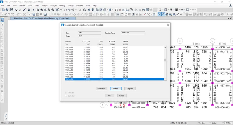
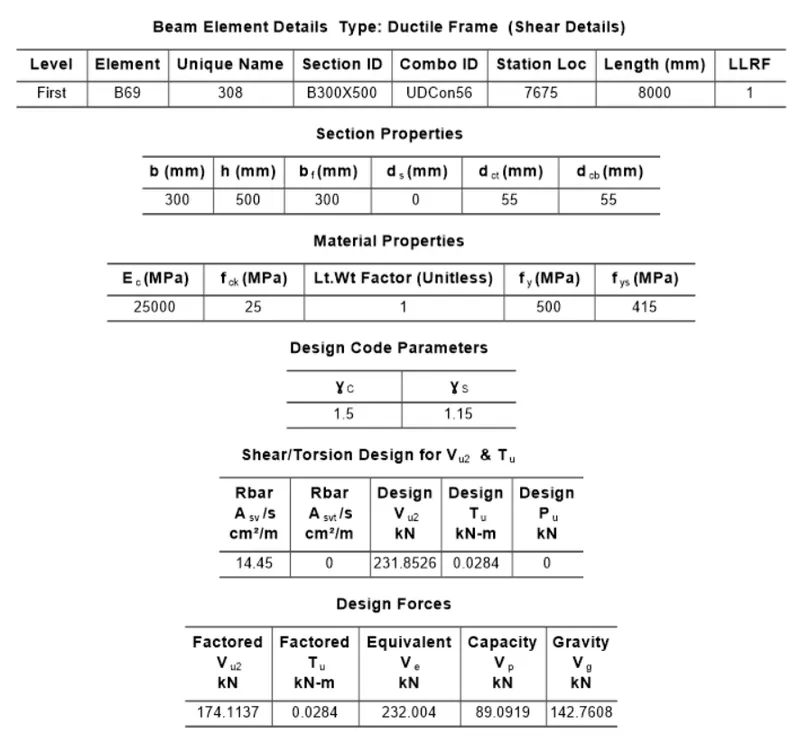
- Next the Shear details will be visible, as shown below.
- As per the clause 6.3.3 the design force is 232 KN.
- We got, Maximum shear force = 174.11 KN.
RESULT:-
- The beams are designed successfully in detail from the ETABS software.
- Provided the details of longitudinal and shear reinforcement for the two continuos beams.
- And also calculated the value of maximum shear force in the continous beams using the ETABS software.